IRONCAD Tutorial Video
Deconstructed! 3D Modeling Techniques Defined
A New Level of 3D CAD Design! Far Beyond Drag and Drop!
I got into a discussion with Richard
Serna, Sales VP of IronCAD. I told him the way I do IronCAD
tutorials, showing a documented step by step process, while he the
preferred the video based approach. Finally we agreed that both
together should provide a much better learning experience.
You can see all of my comparisons to the major products
in this article.
3D Modeling Techniques Defined I this article Solidworks claims you can learn "Solidworks in 5
minutes. We claim you can learn IronCAD in 1 minute! It is quite
humorous!
Now Richard is no stranger to doing video here he took the above
article and created this video "Learn IronCAD in Two Minutes"!
Richard is English and is also know as “IronCAD's Geico
Gecko!” When you watch the video you will see why!
IRONCAD Tutorial Video
Deconstructed!
I saw this IronCAD Tutorial Video presented by Cary O'Conner
IronCAD VP of Marketing. Both Cary and I have been with IronCAD
since the very beginning. He is very familiar with IronCAD and give
a great presentation. Myself, I have been selling, supporting,
training and using the product in my own mechanical design business.
As a user, you don't keep up on most of the latest features and
don't dig into many of the capabilities you are mostly focused on
getting job done.
I have worked closely with another IronCAD
dealer that was doing the Webinars. He is great with doing live
presentations. As I would watch I would see many things I did not use
or even realize were there.
That is one of the wonderful
things in watching a Video of another person using a CAD system that
you use. But Videos are fine, but unless the presenter is
meticulously going through each step it is a bit difficult to
follow.
One fellow that represents another CAD system said I
should create videos, because I
compared his product in a couple of articles to step by step
instructions with images. Well, in his videos that
are comparisons to Solidwork doing the same model showing how his
product is faster. Nothing surprising there there are many products
that out perform Solidwork especially IornCAD and ZW3D.
His
Videos show him going to obscure icon to obscure icon, yes,
showing it being done much faster, but leaving you in mystery about
how he did it.
Here is Cary's video. As I watched I could not
keep up with the commands he used. He went very fast and was using
command I was not familiar. So I decided to "deconstruct" the
process and show it to you as a step by step tutorial.
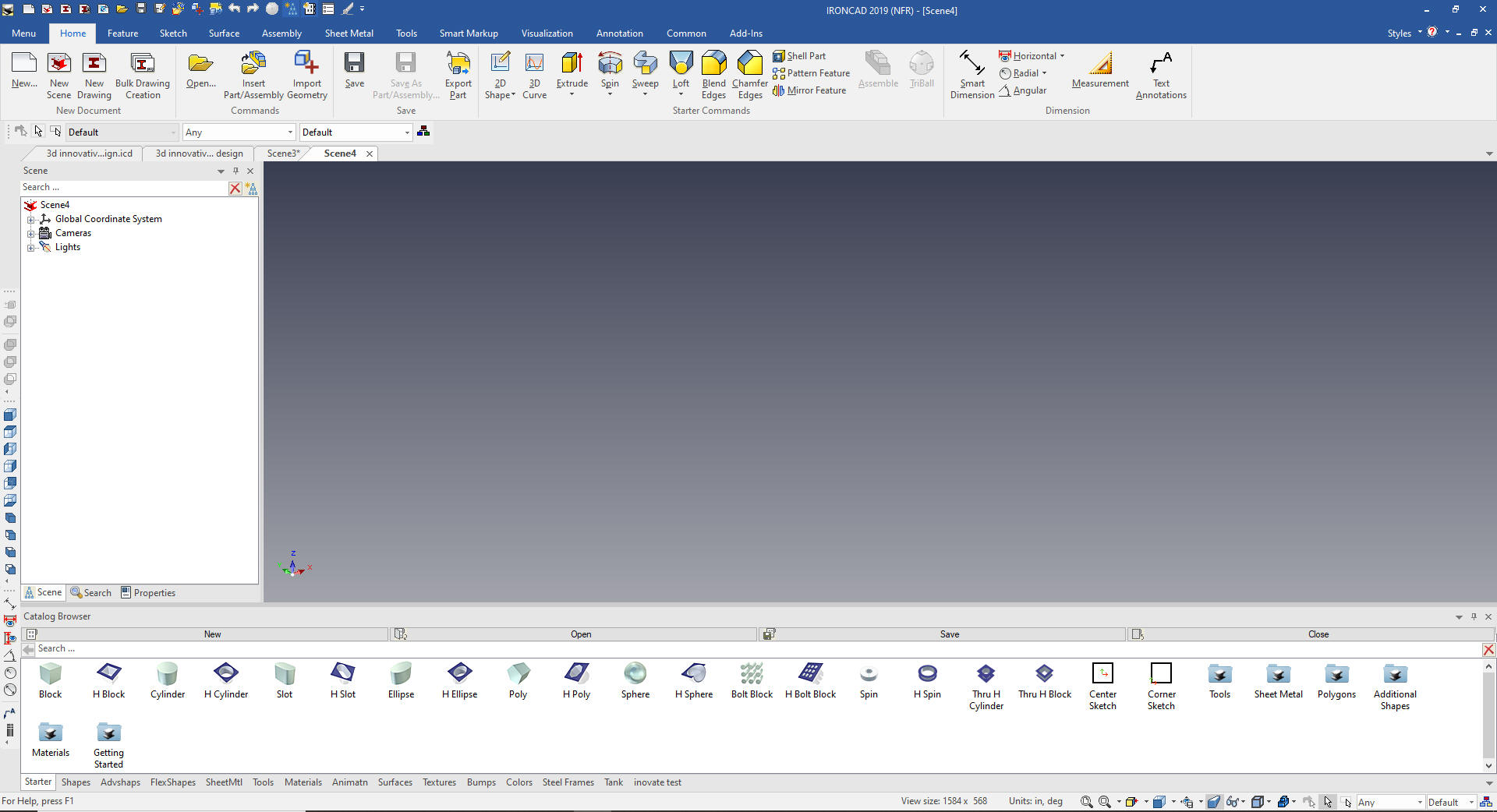
So let's get deconstructing
We start with a new file. I have locked the catalog so we can
see it. You mostly work with it with the auto-hide option to have
more space to work.
The
first thing we do is drag and drop a block into the scene and size
it.
Why does IronCAD call it a scene instead of a workspace?
IronCAD was first released as a graphic design program called
Trispectives. It still has much of the graphic design functionality.
It truly is a wonderful mixture of professional 3D CAD and graphic
design, which puts it in a much more flexible category as compared
to the Pro/e (Creo) clones.
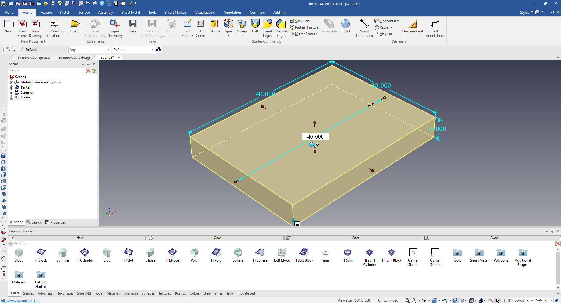
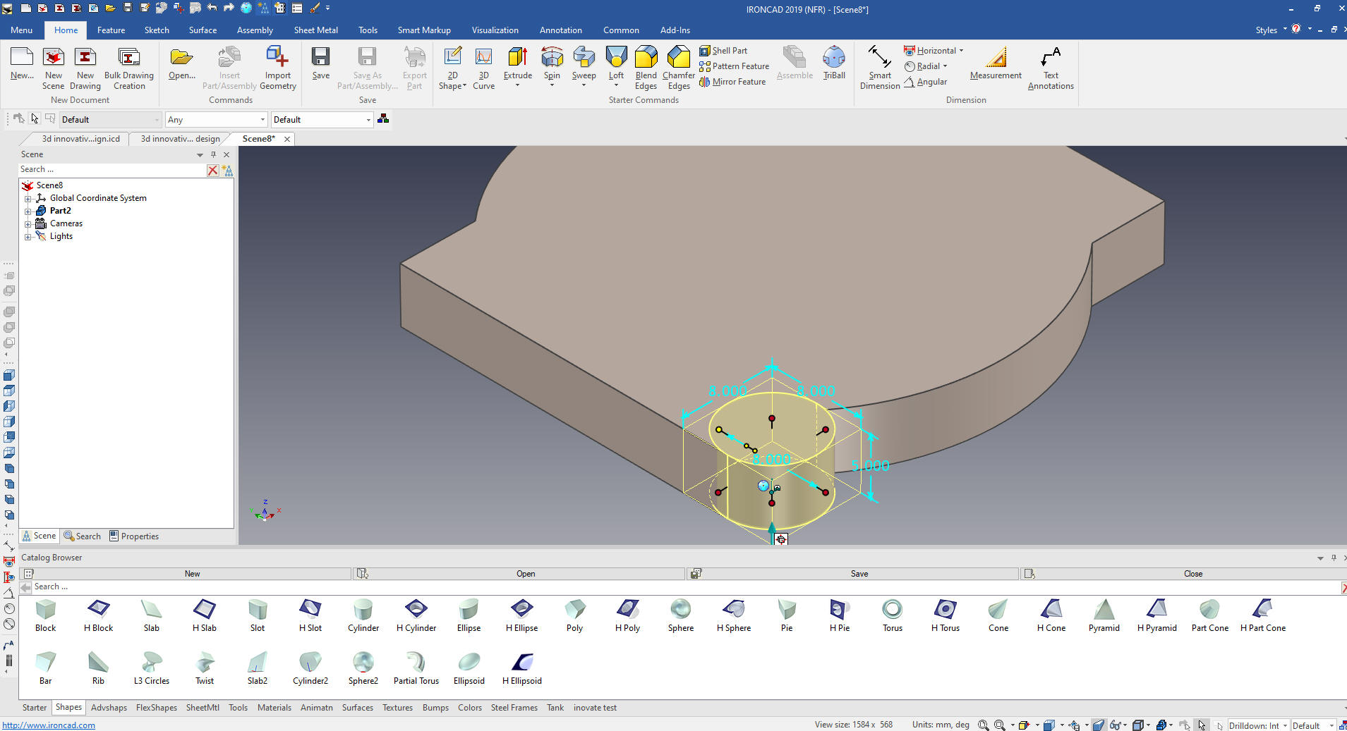
We
now drag and drop a cylinder to the mid-point of the block. IronCAD
offer a variety of points mid-points of feature like here, ends of
lines, mid-points of lines, centers of circles automatically. We set
the height to match the block the pull the handle to match the edge
of the block. We do this by holding down the shift key to recognize
these point.
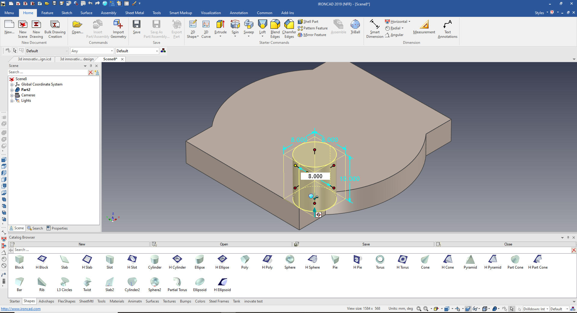
We
now drag and drop a cylinder to the top face and set the size. The
nice thing about watching someone else model is you learn a new
trick or two. I have been using IronCAD for 21 years and just found
we could do this. We just hold the shift key down and move it into
place with the quadrant tangent with the edge.
We
size the cylinder to match the block
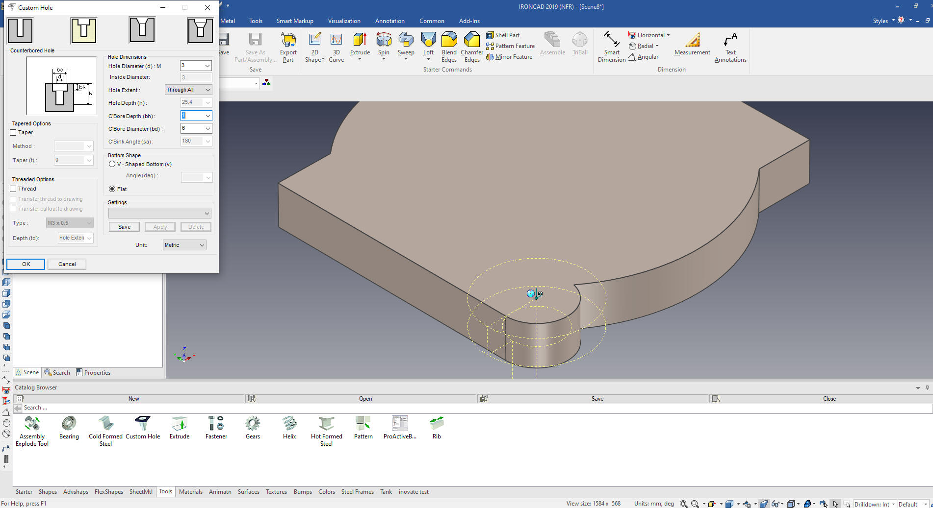
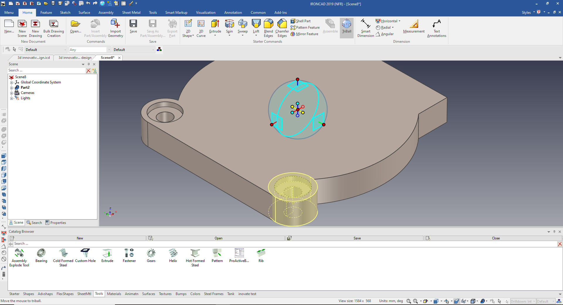
We
drag and drop a custom hole from the tool catalog.
We
select the boss and hole.
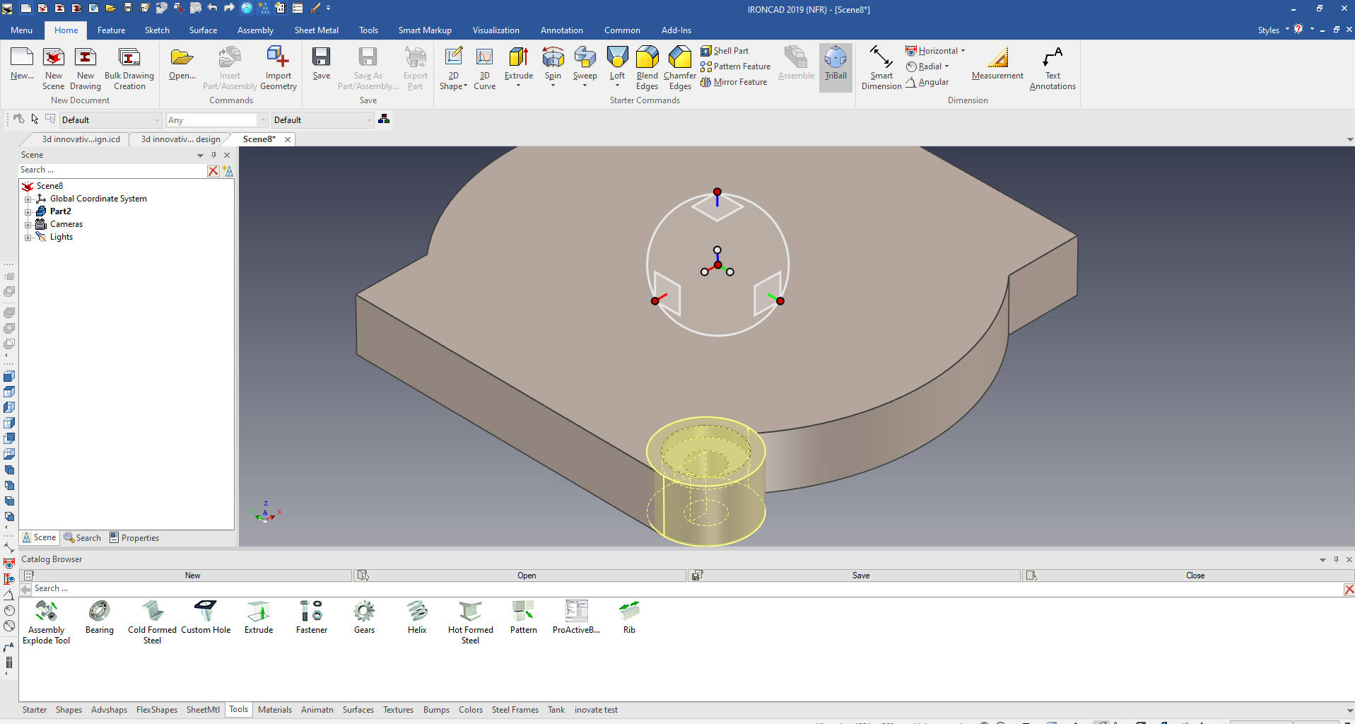
We activate the Triball and hit the
space key to move the Triball only to the center of the cylinder.
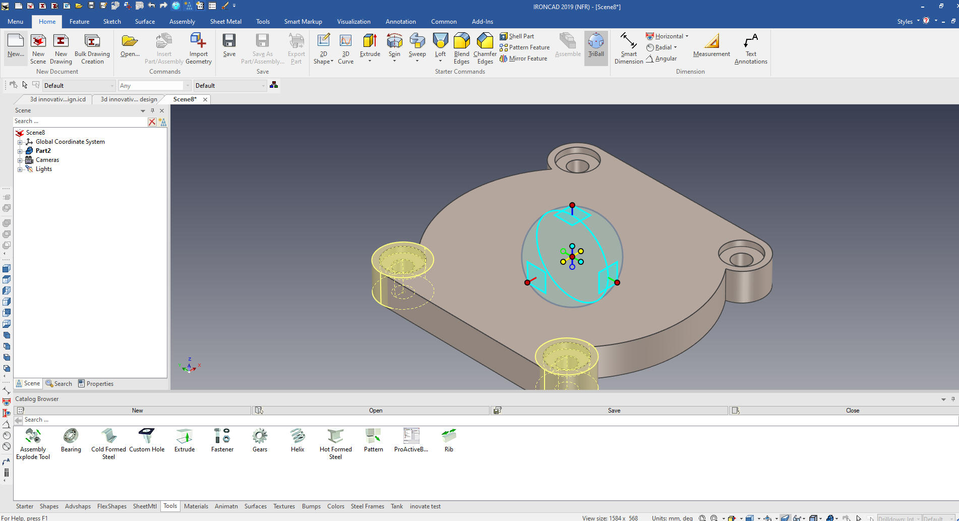
We turn the Triball on by hitting the
space key and select the relative small handle inside the Triball
and select mirror link.
We turn off the Triball and select the
new hole and boss turn on the Triball and mirror link the selected
features.
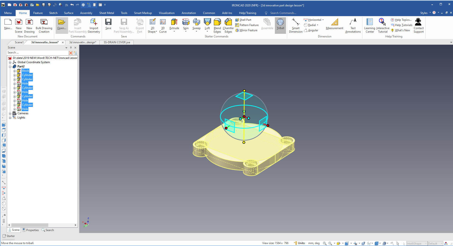
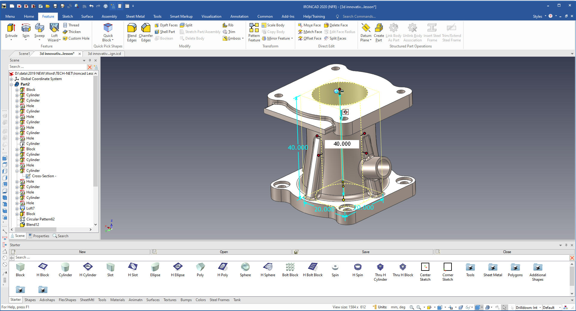
We set the feature selection to
intellishapes and window the complete part. We turn on the Triball
and deactivate it and move it to the center at the bottom of the
shape and up 20mm and activate
it.
Like Cary says planes are not part of IronCADs history.
Planes are implied or part of the feature. The Triball is used
through out the design process in the place of defining planes.
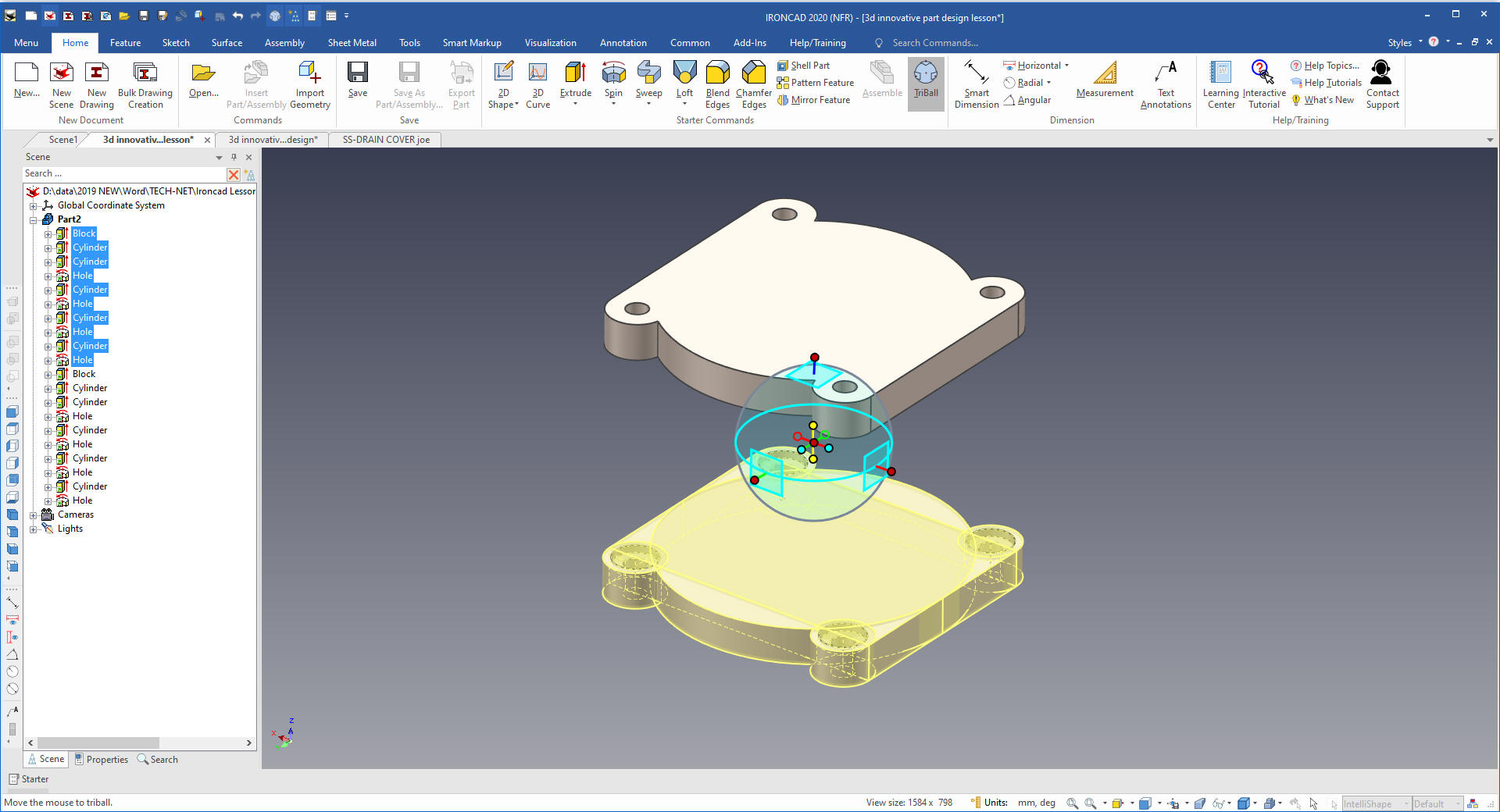
Again we select the relative inside
handle and mirror link. Linking allow the ability to change either
of the shapes and the other will also change.
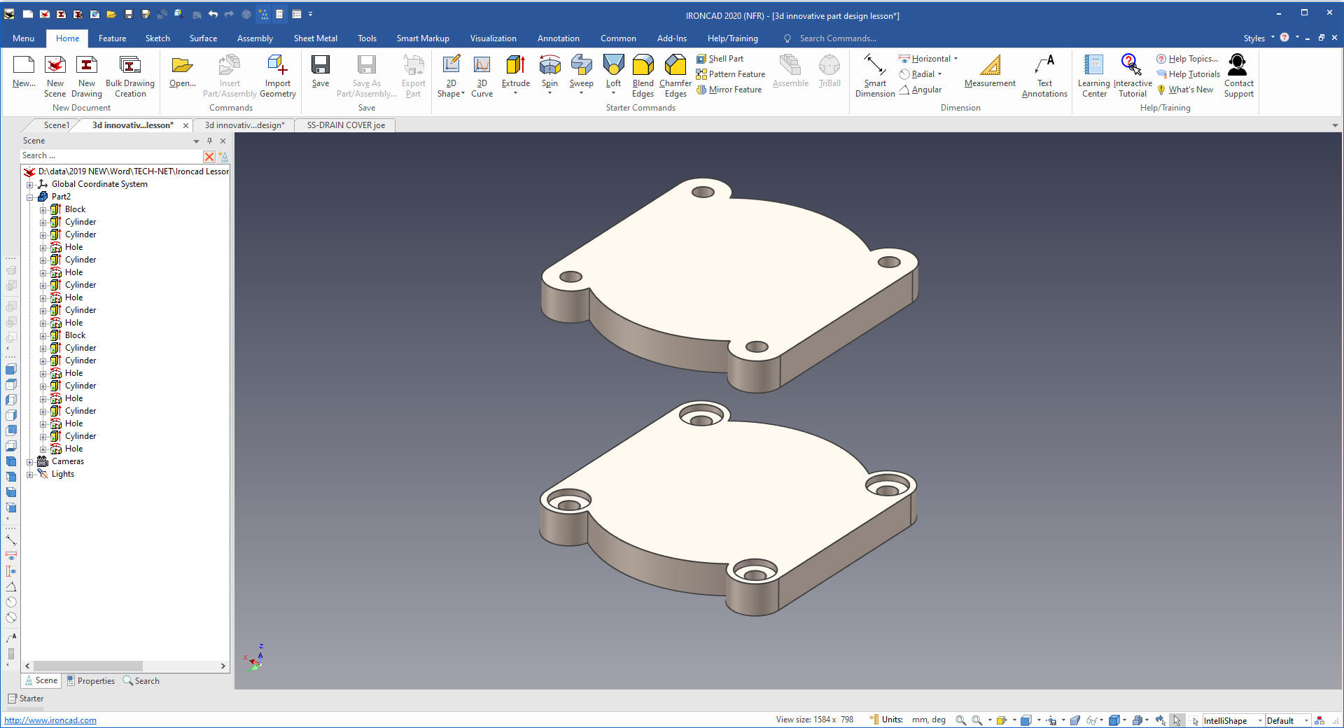
Now we will create the loft. I have
found that we use extrude about 70% of the time, spin/revolve 15%,
sweep 10% and loft about 5%. So in this case, Cary is showing how
the the
loft feature works. I would probably use a spin/revolve which would be
much easier to define and control.
We select the Loft Wizard
and locate the origin in center of the bottom shape that will bring
up dialog box! Which we will select Add Material.
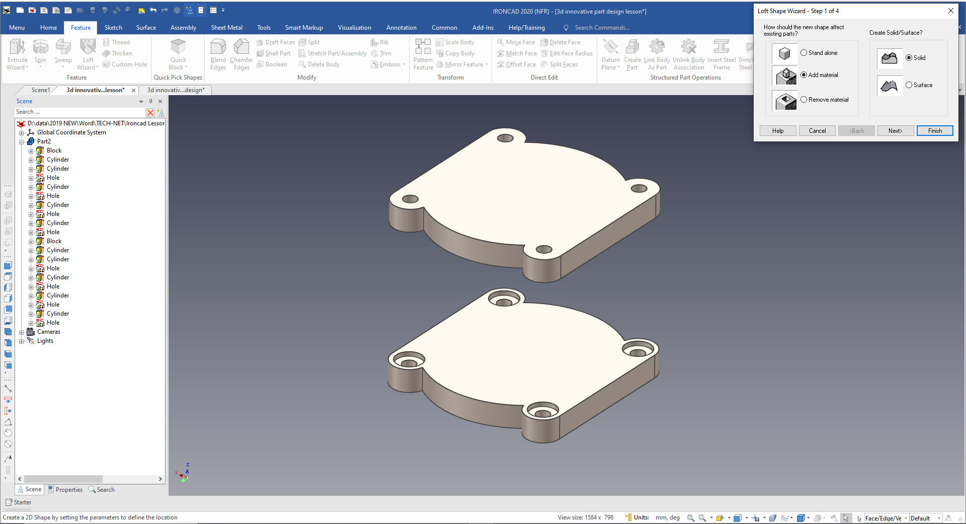
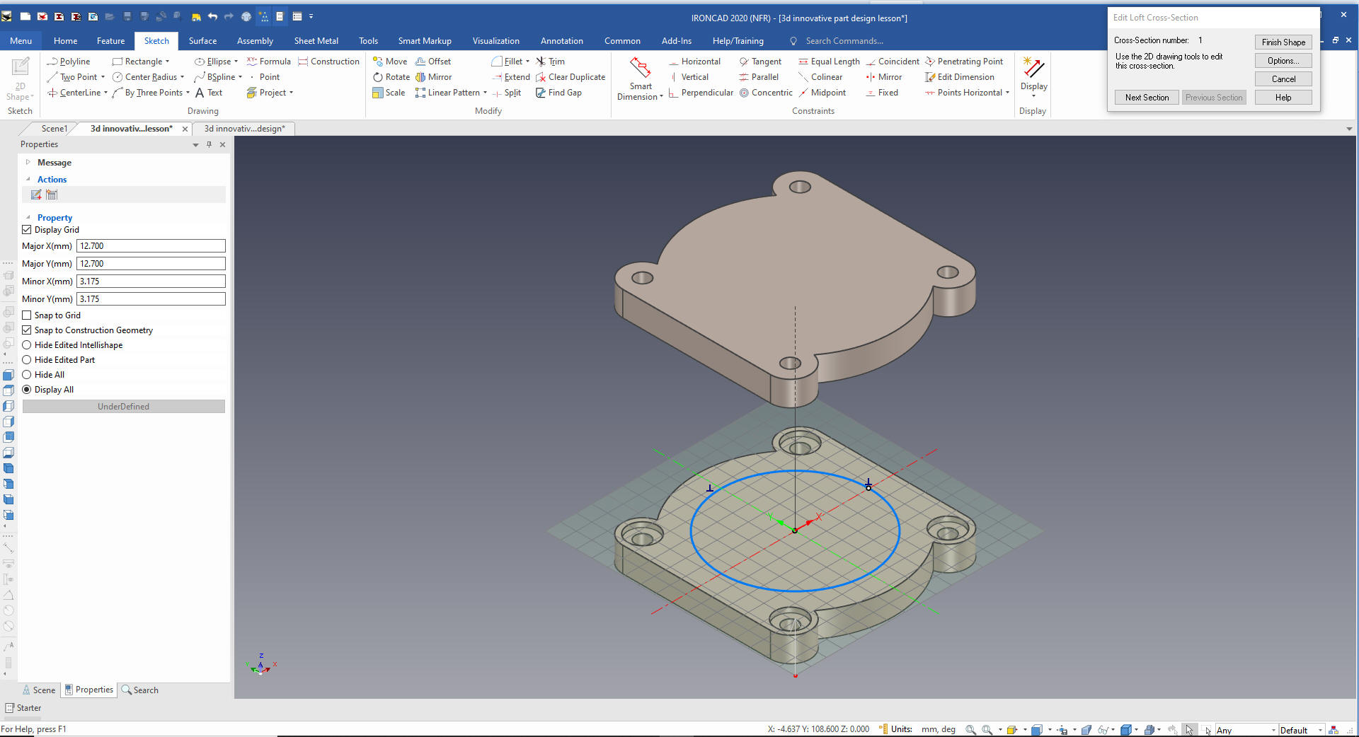
We now specify how many sections we
need.
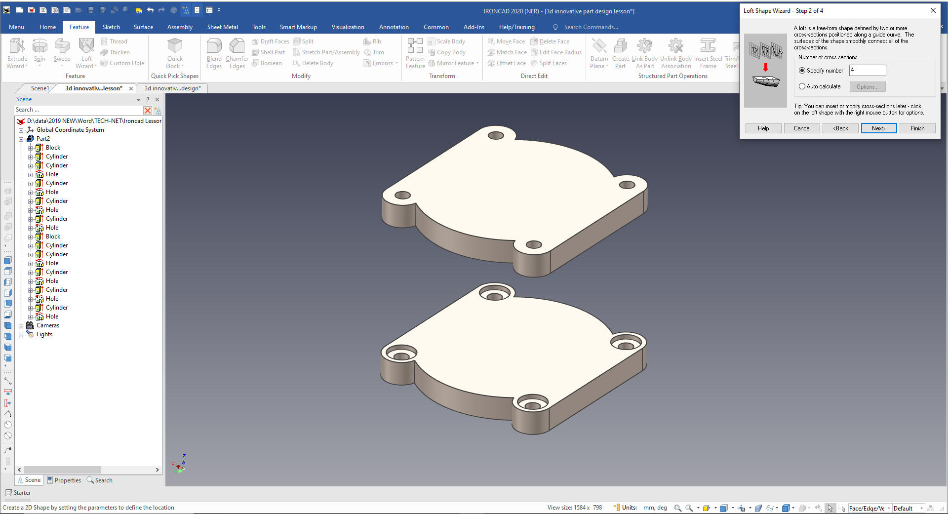
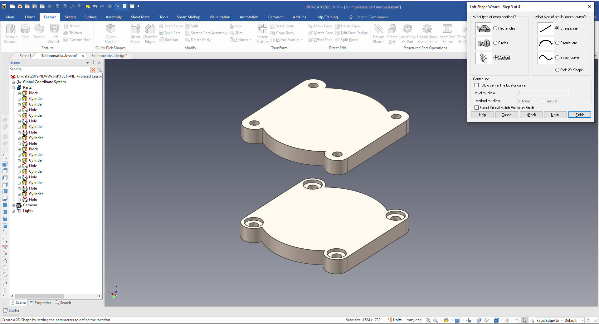
We select the type of Cross-Sections and
locator curve.
We set the type to custom cross-section
and profile locater curve
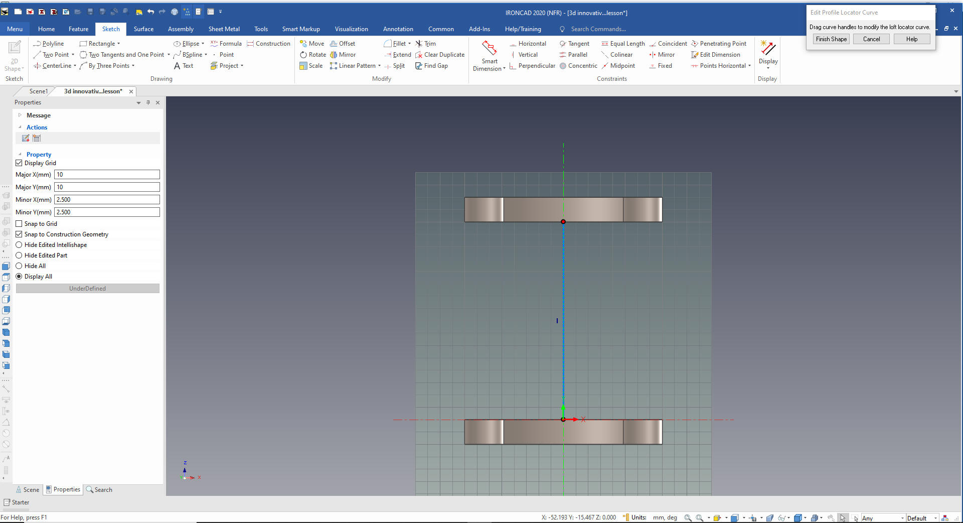
We
snap the length of the line to bottom of the top shape.
We create our first circle.
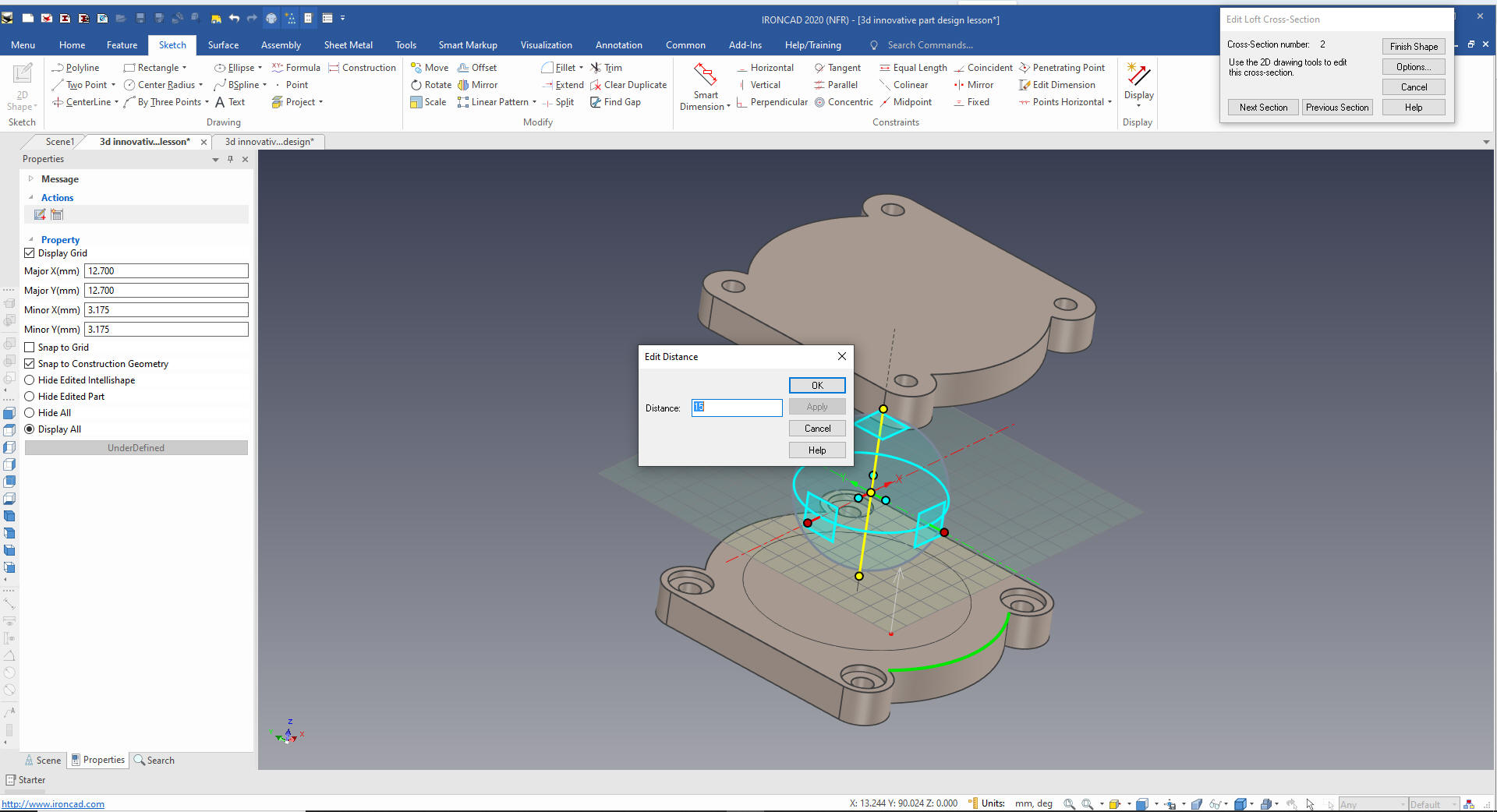
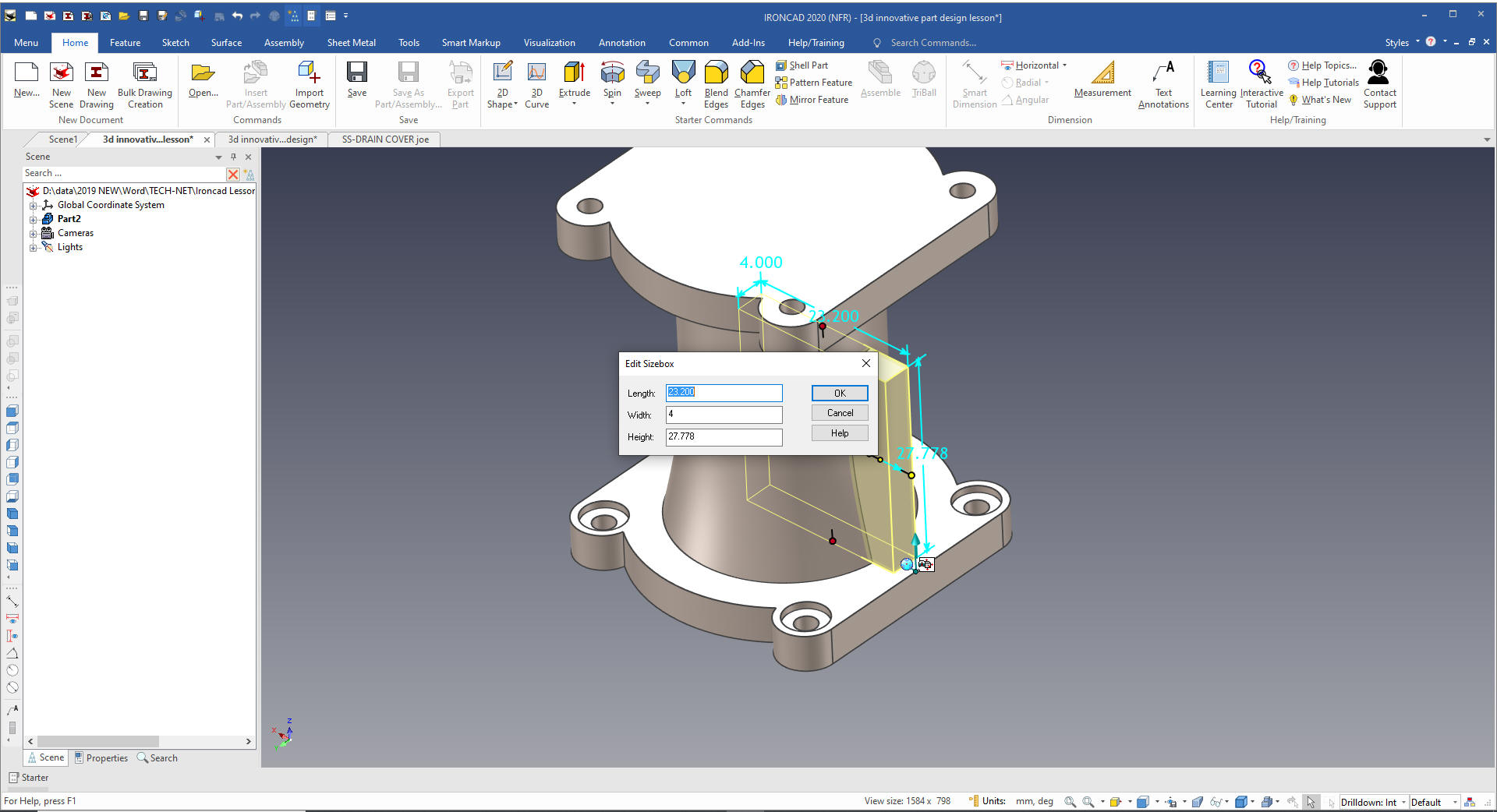
We use the Triball to locate the sketch
plane at 15mm. Cary rushed through this function, it is very simple,
but has defined steps.
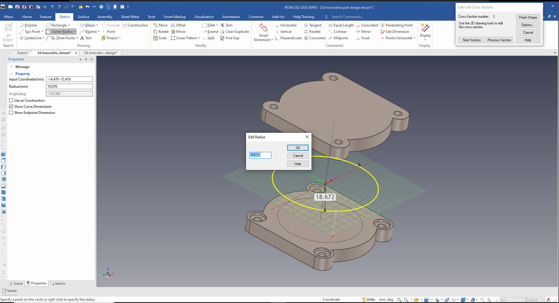
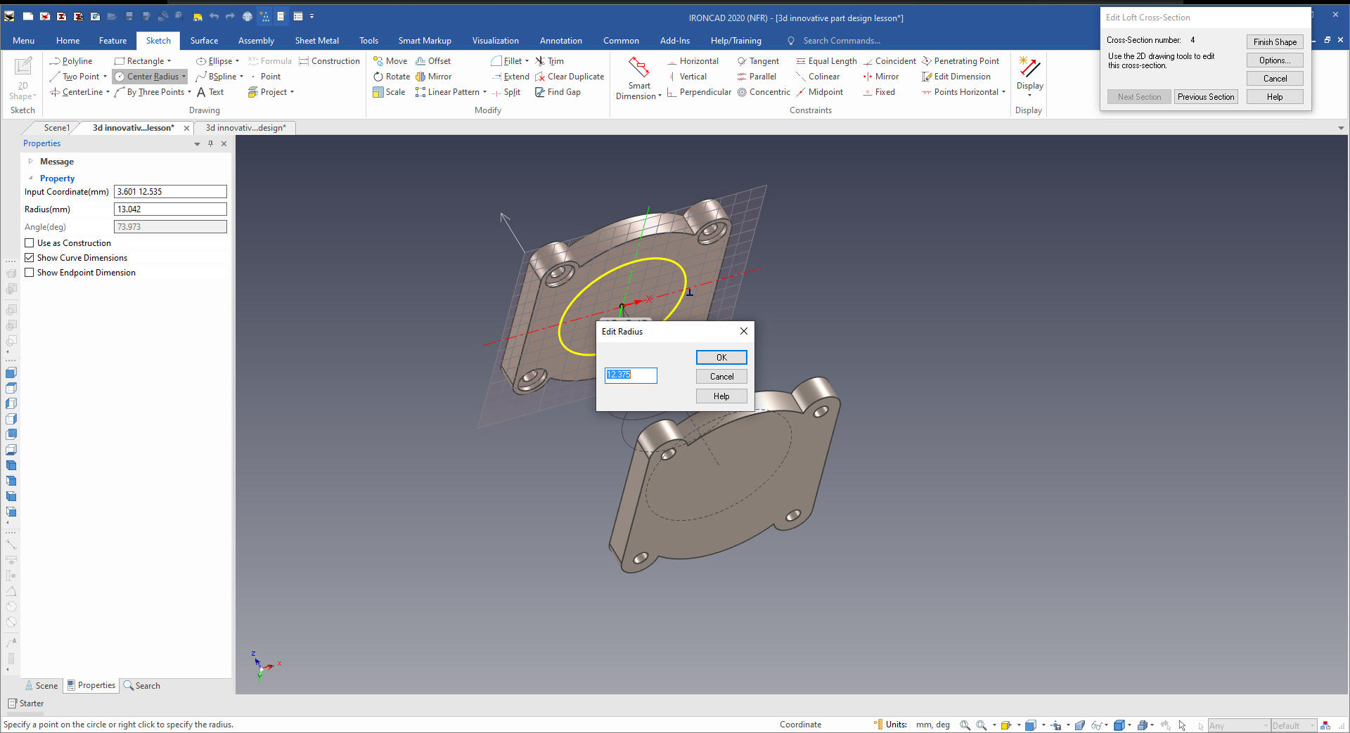
We use the circle radius command. If you
use the right mouse button the dialog will come up and you can input
the radius. The options is in all of the entity creation commands.
Makes design much, much easier than constraining them.
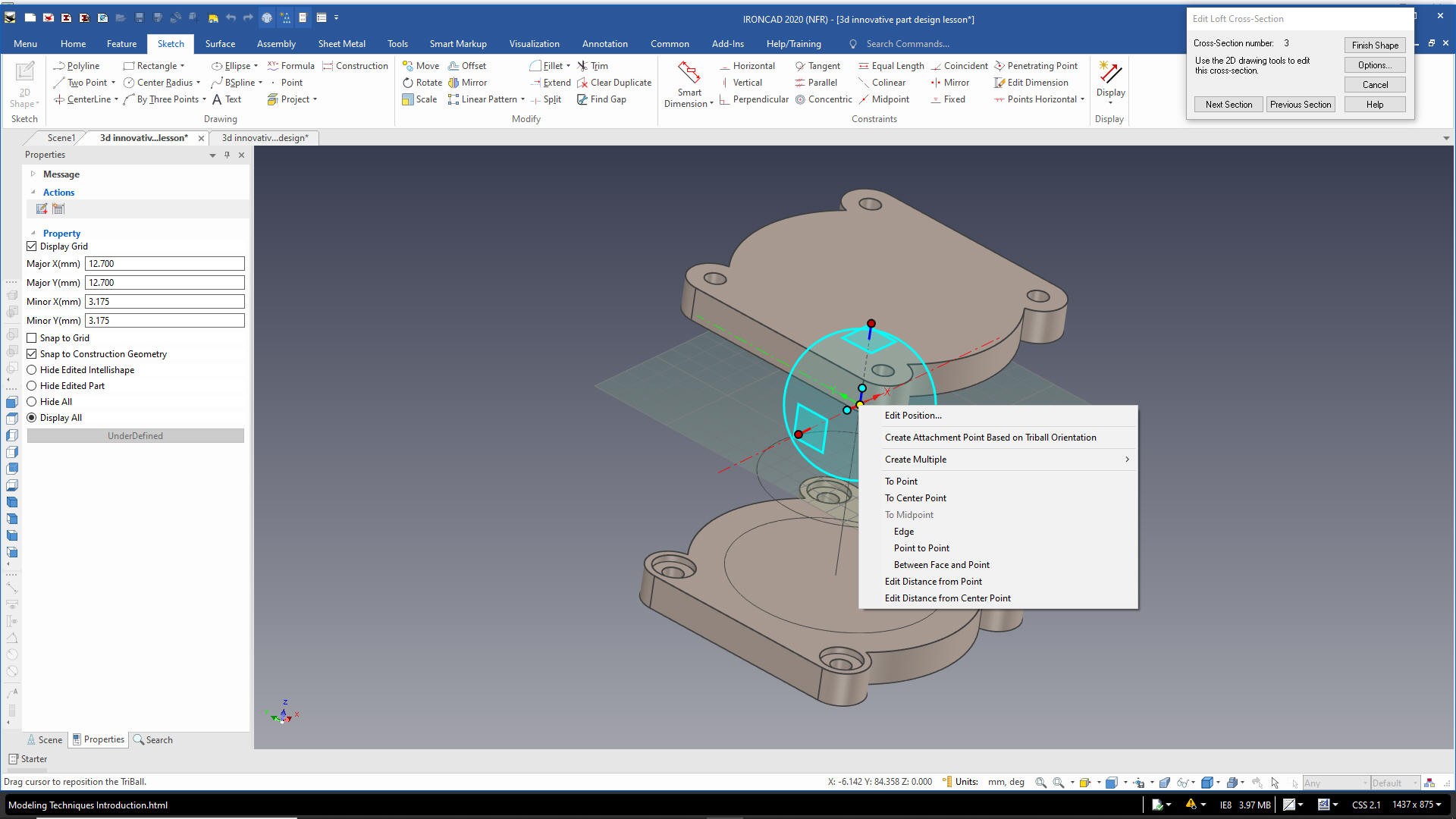
We
select next and locate the plane and create the circle. The Triball
has many location options we use "Edit Distance from Center Point'
and locate the sketch plane at
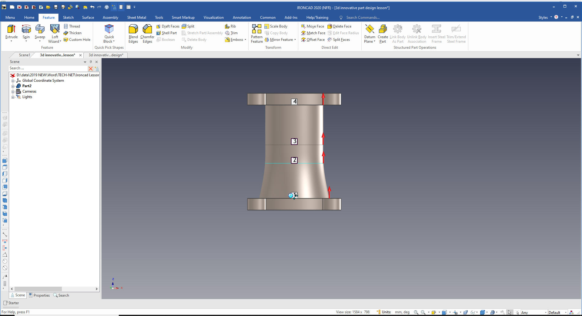
We do
the same with the next section and then the final section.
We
are done with our loft.
Now
for the rib we drop it on the mid-point of the top edge of the
bottom shape. IronCAD recognizes center, edge and mid-points. We set
the size.
We
just edit the relative handle by subtracting the 1.8mm
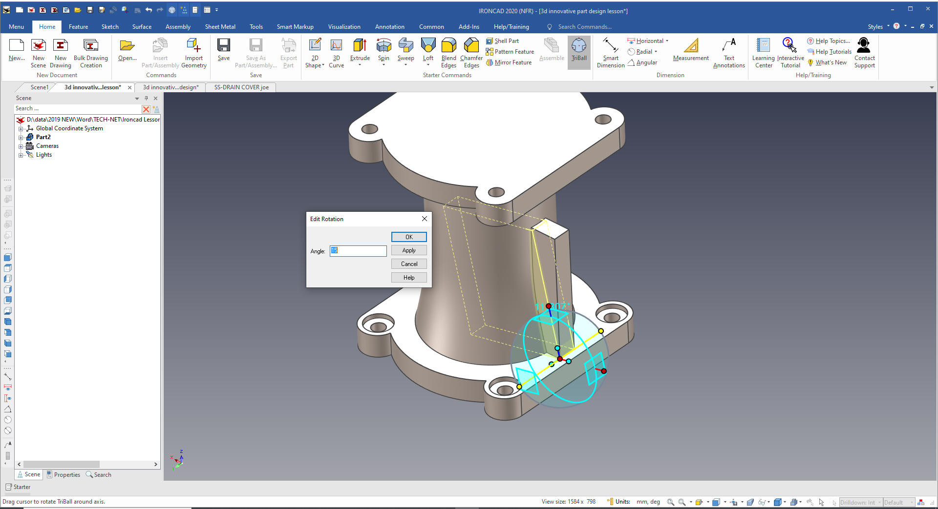
We
now create the taper by just rotating the shape. We can adjust the
size a bit if required after the move. You move the Triball only by
selecting the spacebar.
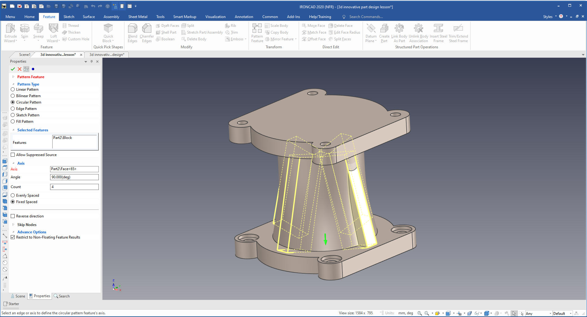
We
will now create a pattern by selecting the pattern command selecting
the feature we want to pattern, select 4 and the axis which would be
defined by any relative cylindrical feature.
You can also use
the Triball, it has full move, copy and pattern functions.
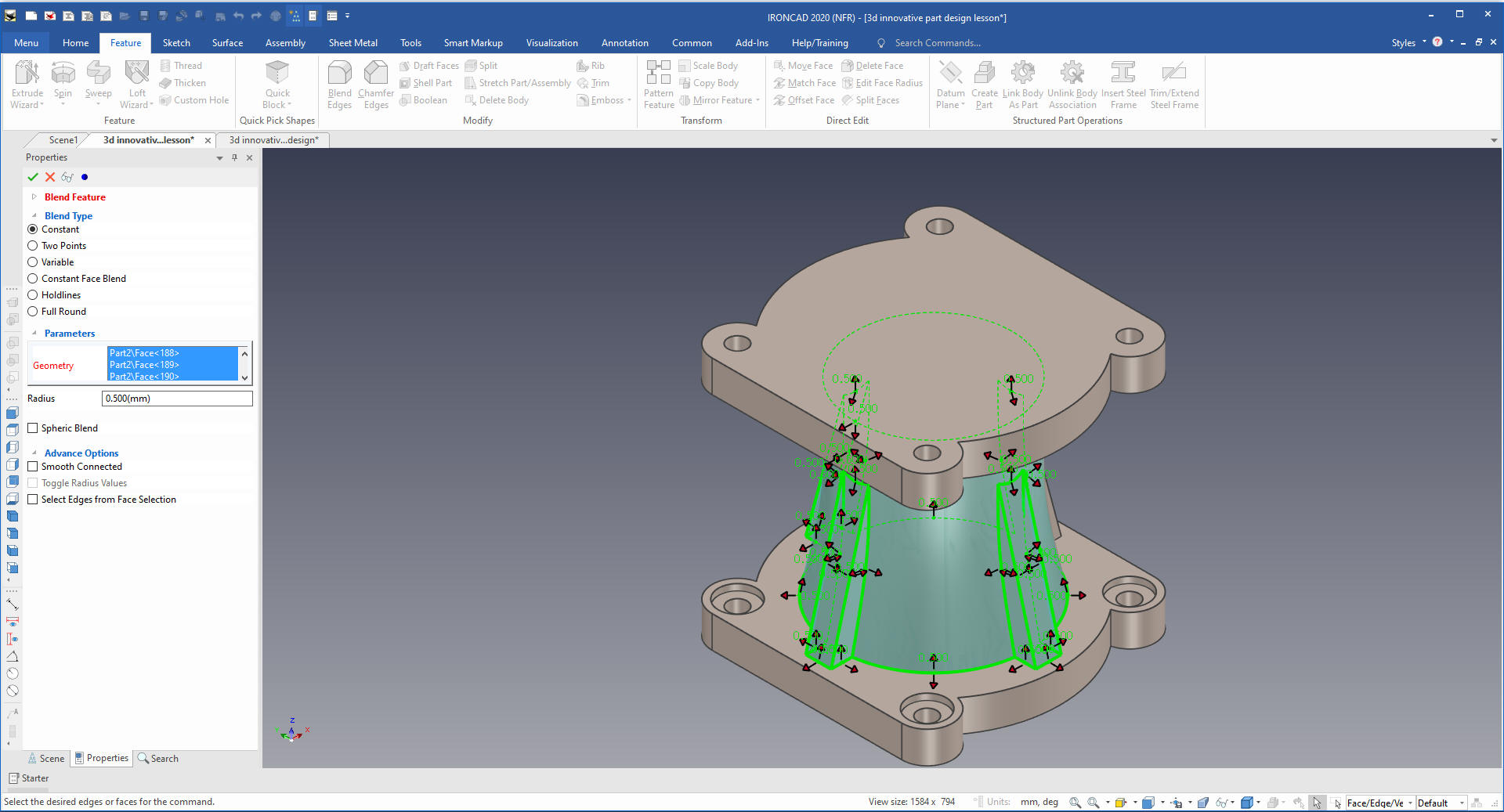
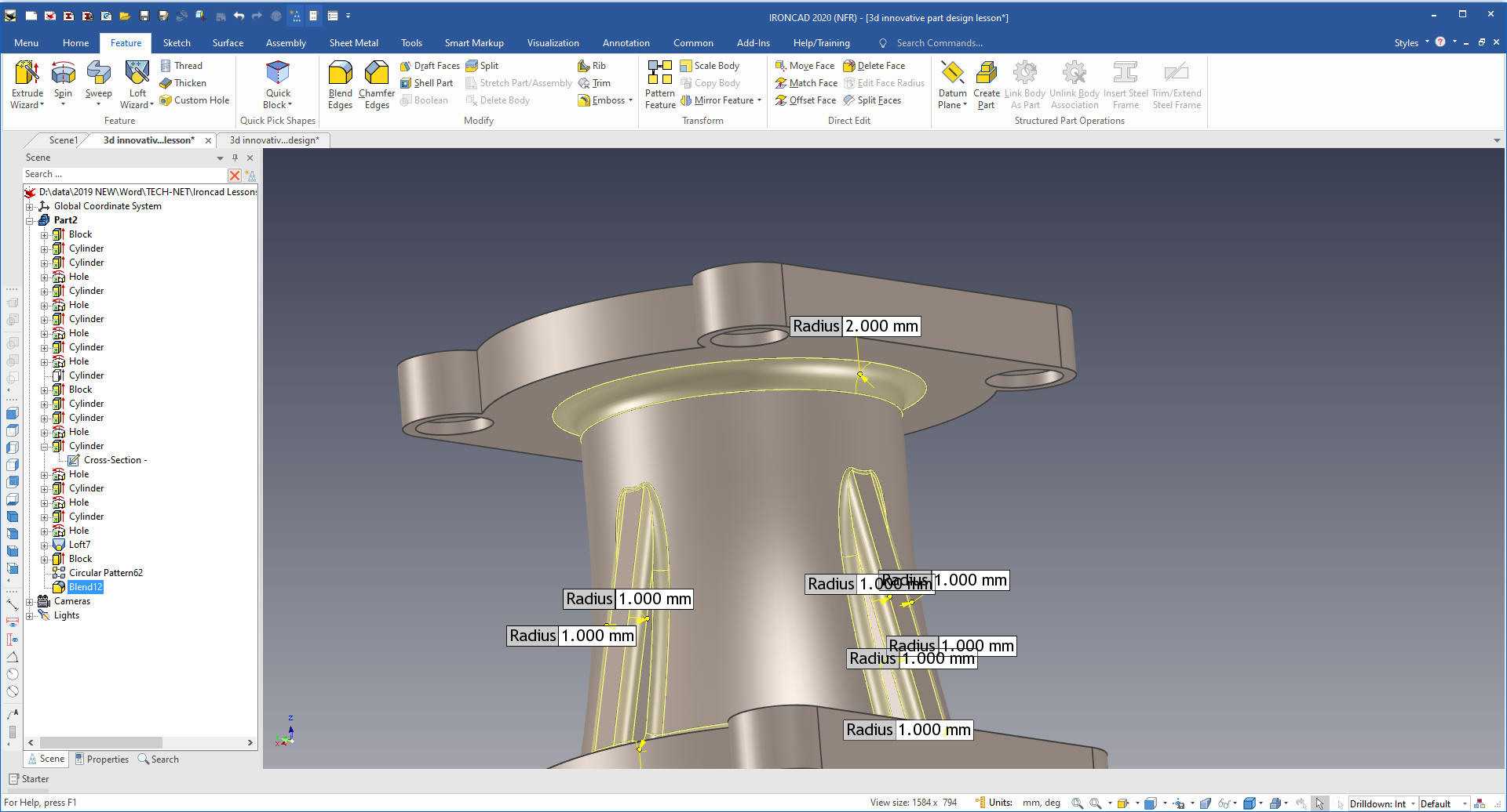
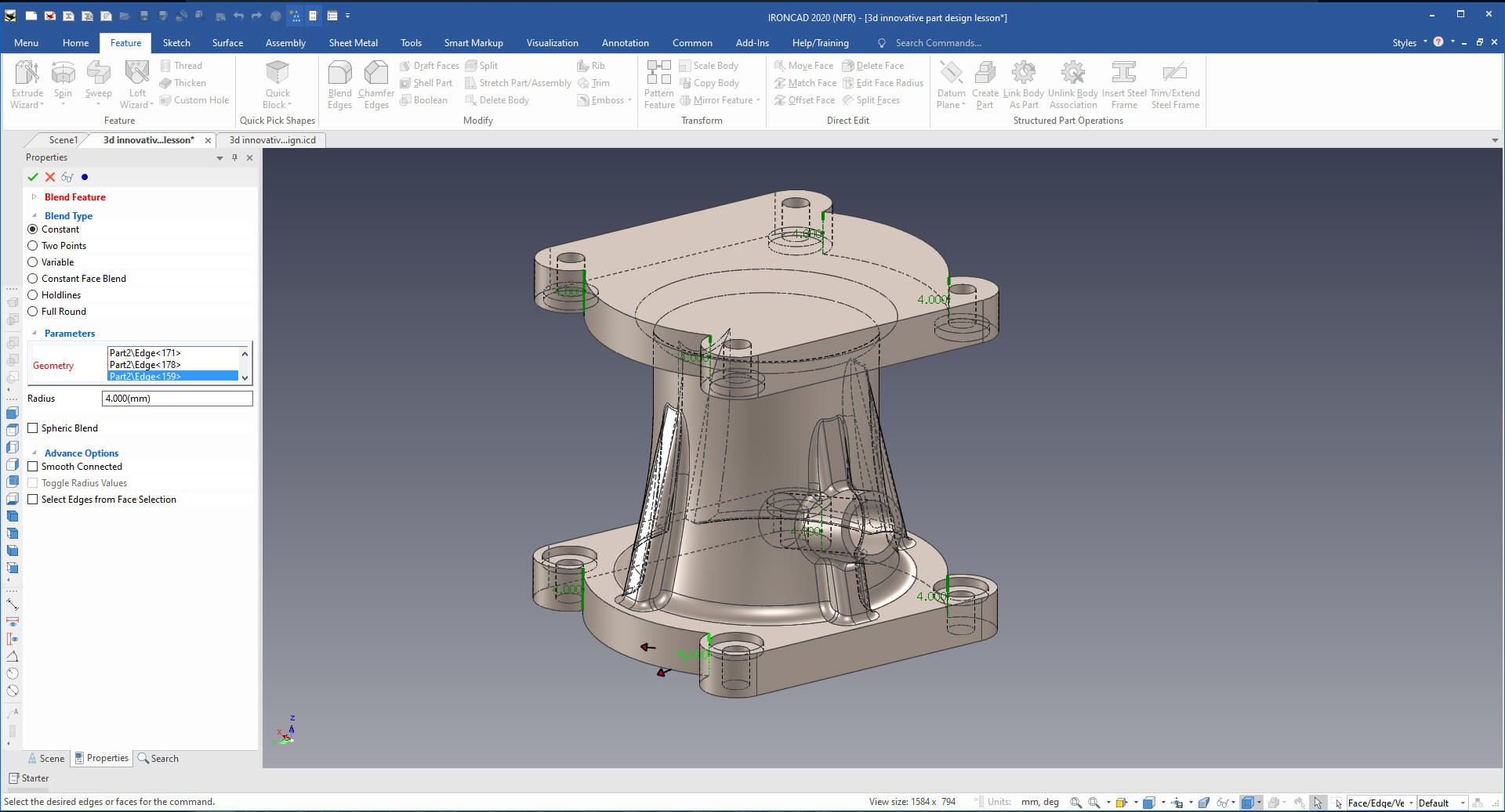
You
change the selection filter to edges of intellispheaps and pick one
rib and the lofted shape and select blend and set it to one.
I missed the 2mm radius change but we can change it later.
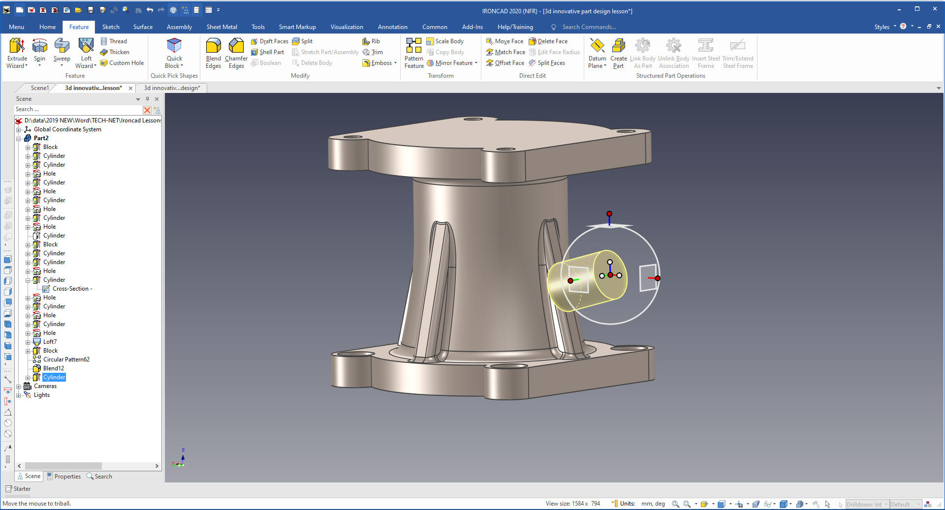
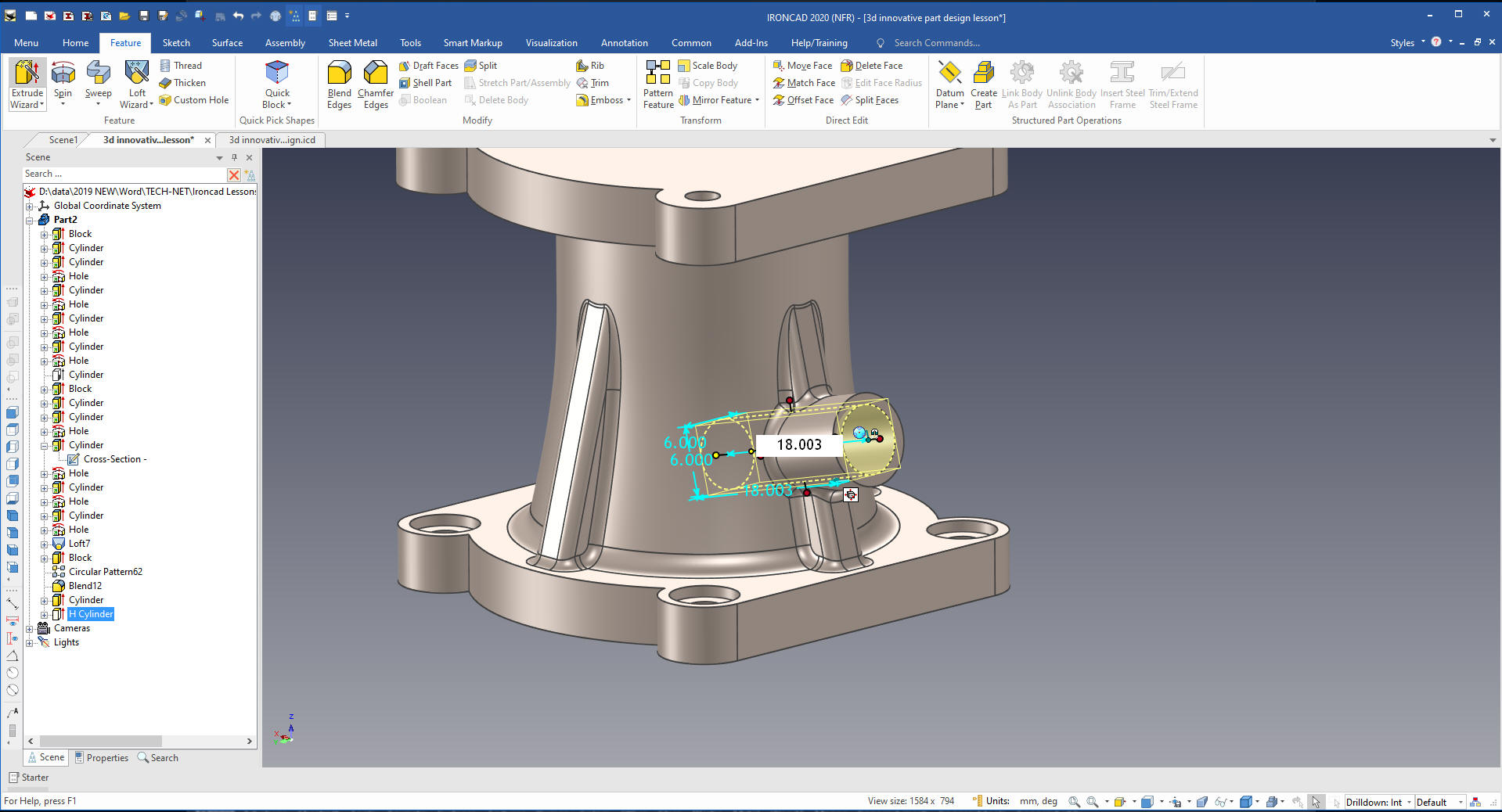
With the boss no one would design the way Cary since it would be
impossible to detail. So I will take the dimension from the drawing
to locate the end of the boss. I do this by creating the boss like
Cary then moving the Triball to global so I can easily locate it.
The Triball allows a massive amount of design flexibility.
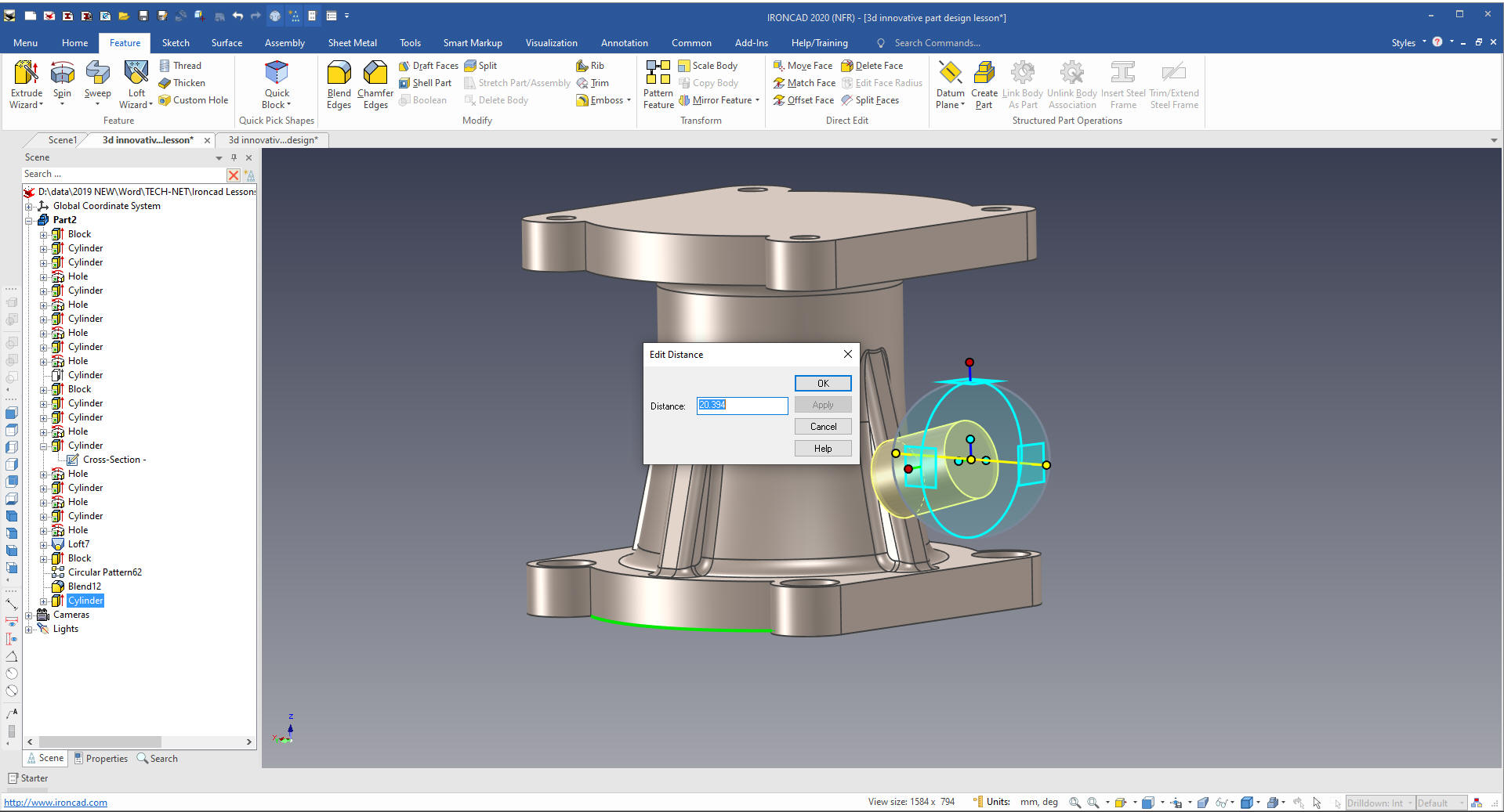
Now we just lock the Triball axis in the relative positions and
select from point to define the location.
We
pull the cylinder to assure it is inside the part.
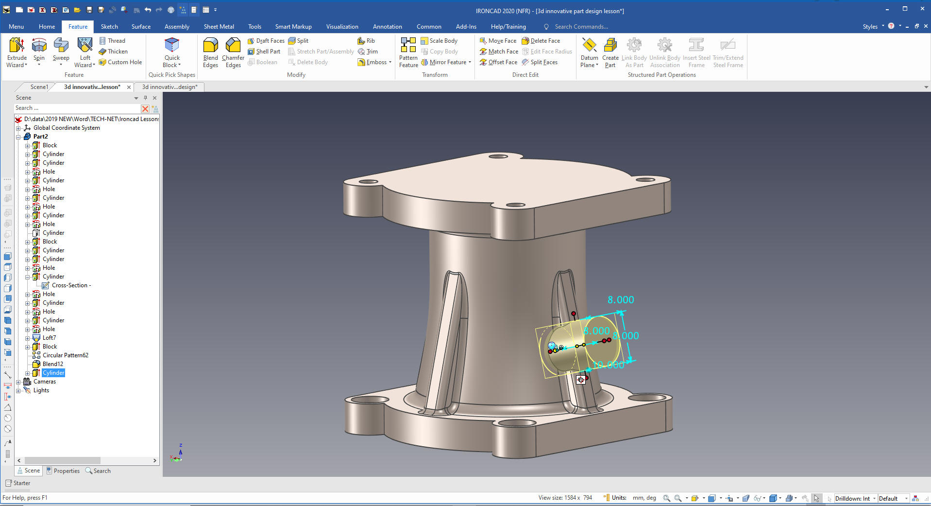
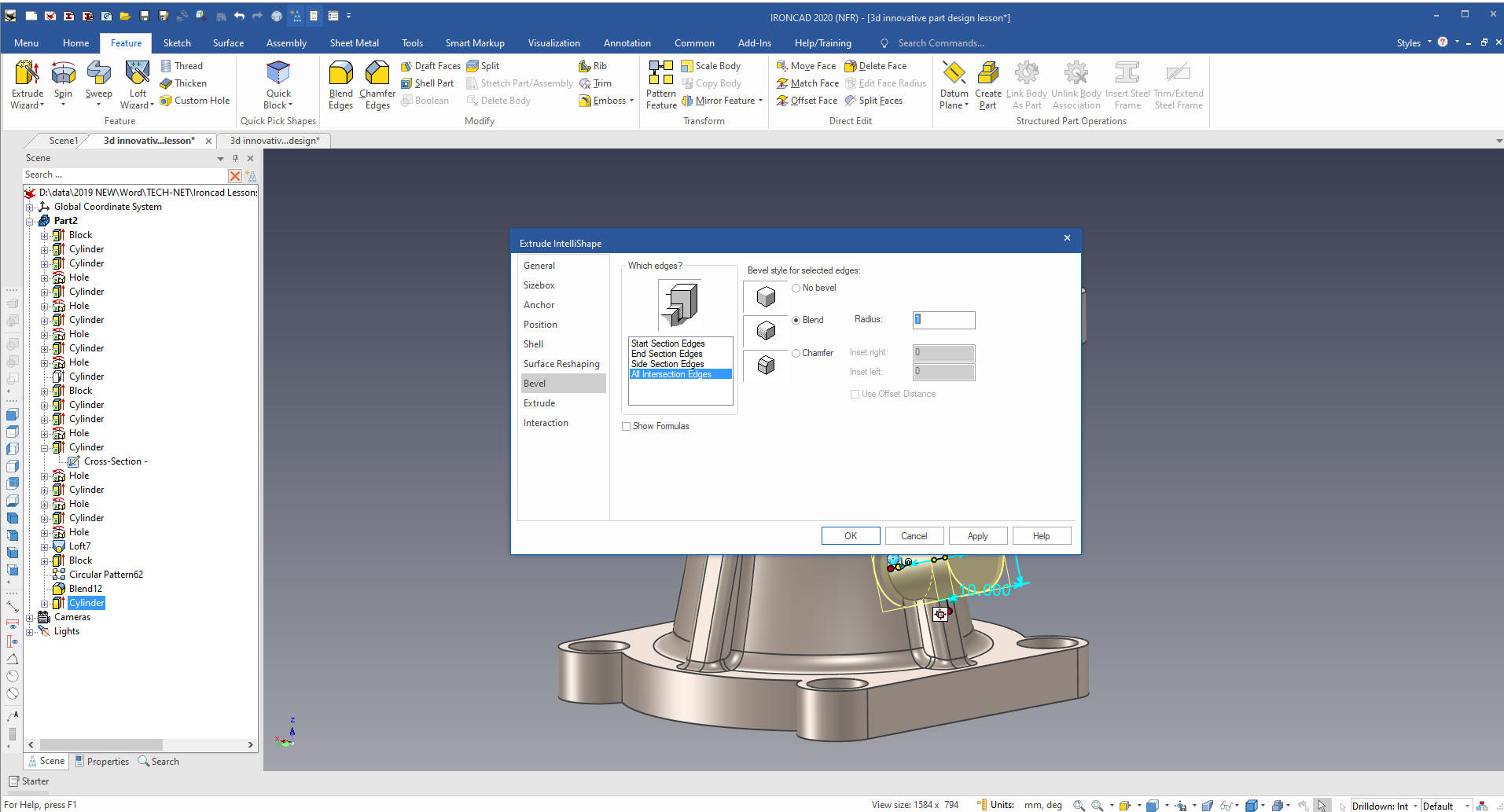
And
we are done with the feature. Now we will show you a bit of
intellishape functionality. We can set the blend by editing the new
cylinder intellishape. I probably don't use this funtionality as
much as I should.
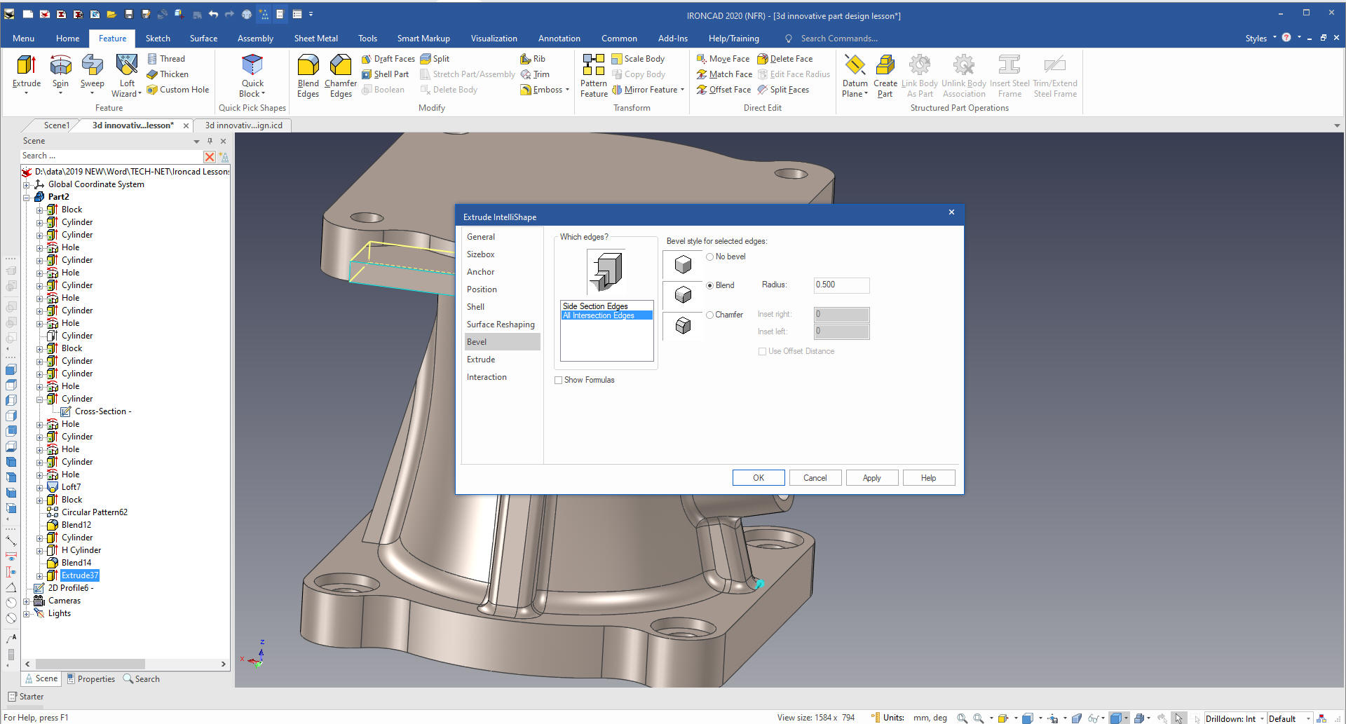
We
create a hole by dragging and dropping a hole cylinder on the face
of the boss, size it a pull it into the part
We
now will add some fillets. Cary must have had an immediate mode
command but you can easily turn on the hidden lines by a
command on the Status Bar down below that allows you to set the
rendering. You can also do it for the complete scene by right
clicking in the scene that brings up the scene options dialog box
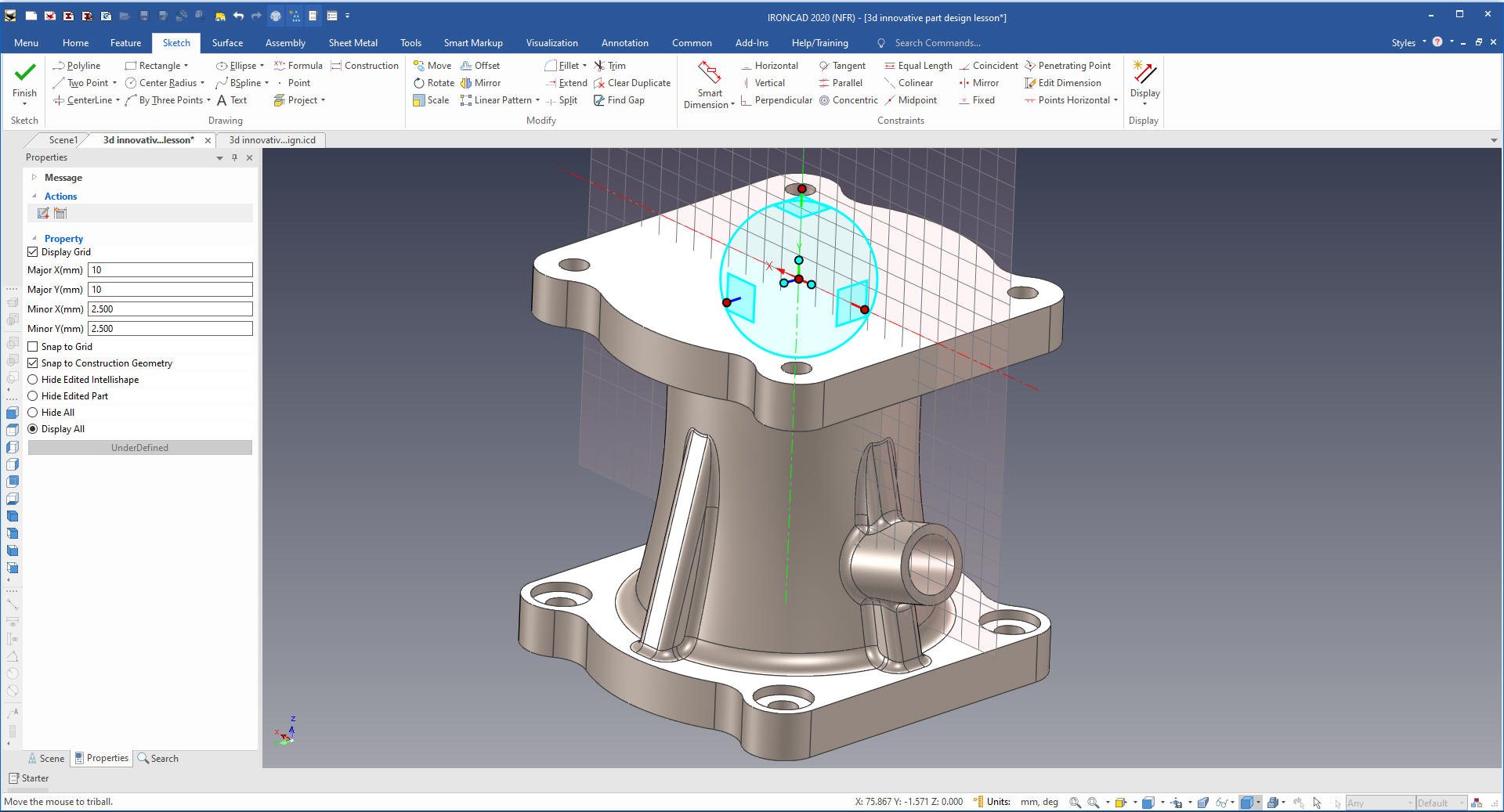
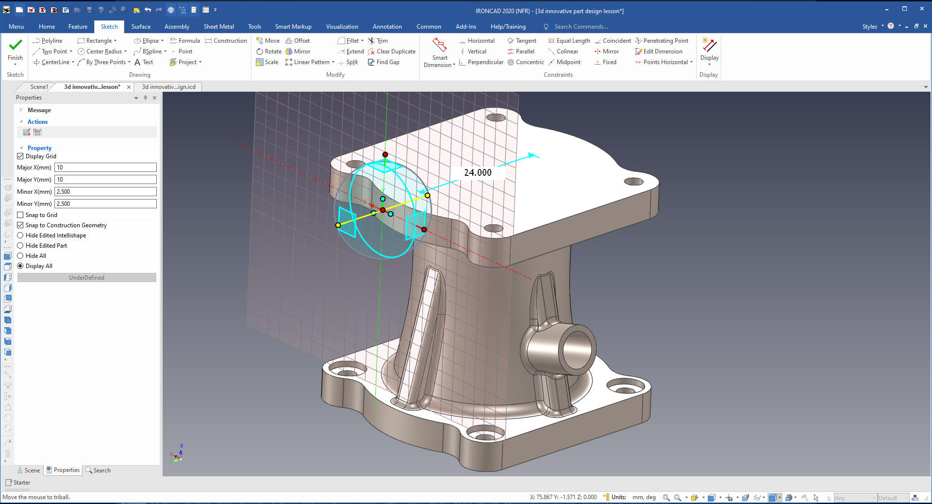
We turn the hidden lines off. Now we are going to create the last
feature and we will do it by creating a plane and sketching it. Like
Cary said we could drag and drop the shape by we want to show how to
sketch it.
We create a sketch plane normal to the top face in
the center of the circle.
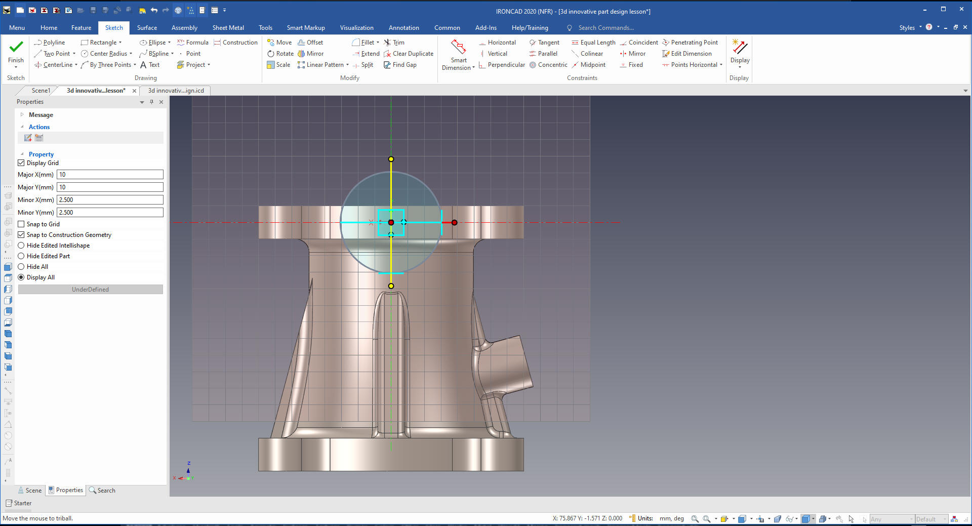
We
move it to the location from which we are going to extrude.
We
now move to the middle of the top shape.
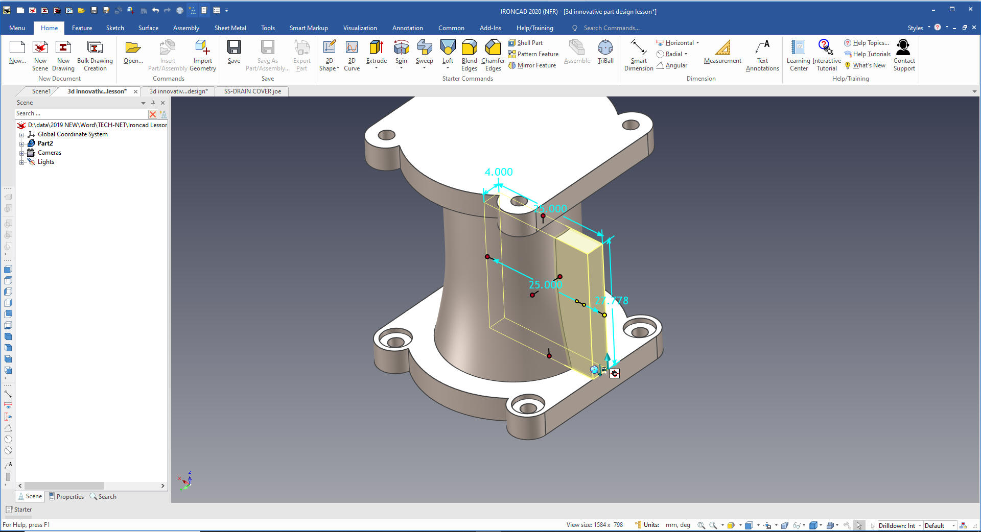
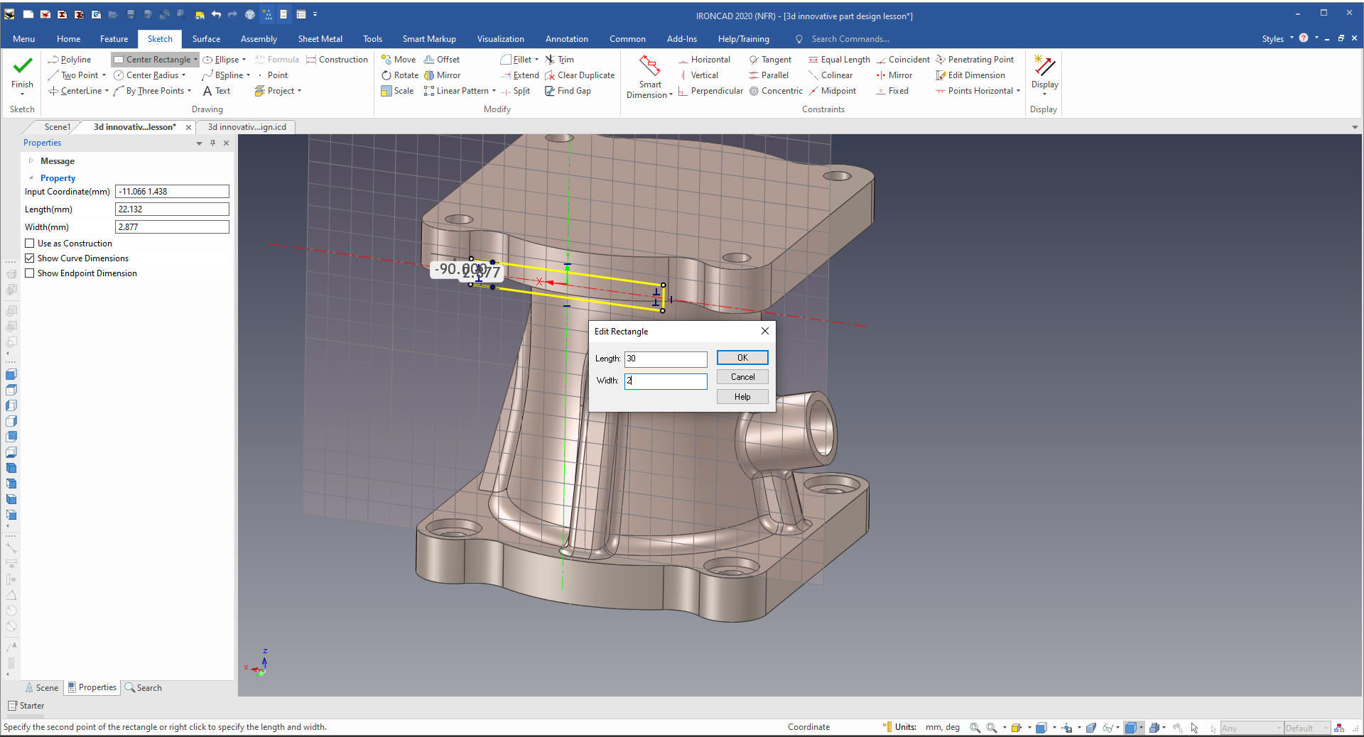
Now
we will create using our center rectangle using the right mouse
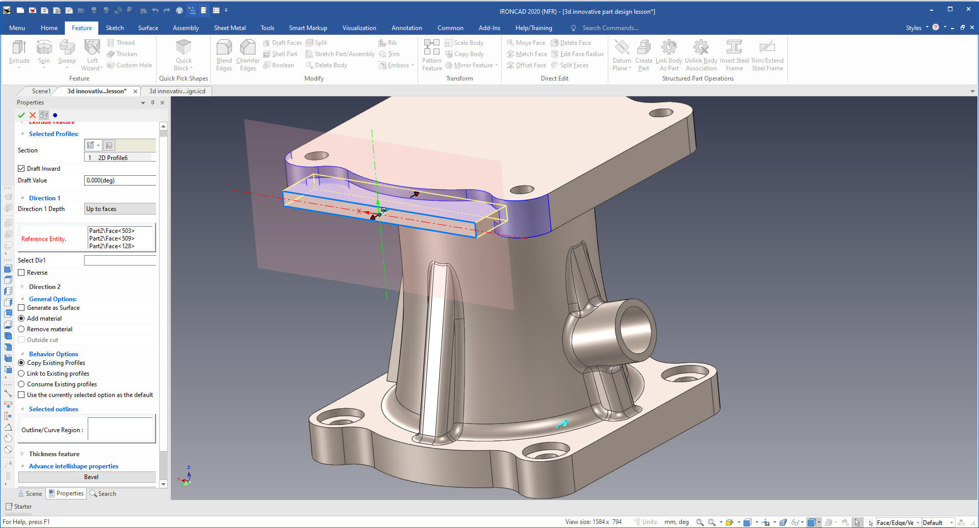
button which will bring up a input dialog box and we put in 30 x 2.
Using the extrude command we will extrude to faces. This is to avoid
intruding into our holes. But we could just move the holes after the
extrusion.
Cary
shows off a bit with the intellishape funtionality. He should
IronCAD is the only CAD system that has it. I am not sure who
thought it up but they were incredibly clever. Lots of things in
IronCAD are brilliant.
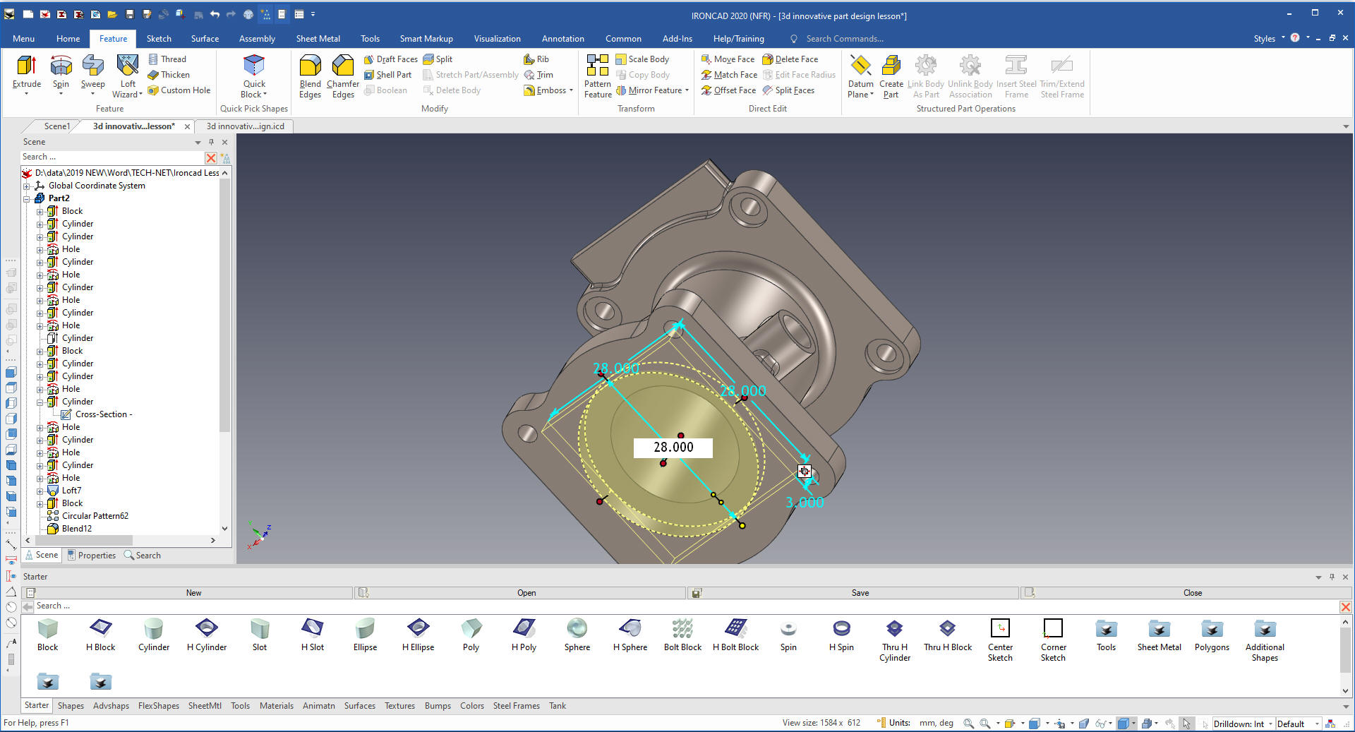
We
now will add a through hole by dragging and dropping a hole cylinder
to the center of the top shape and pull it through to the bottom and
size it.
Now
for the bottom counter bore. We drag a hold cylinder and hold the
shift key down which locate it at the center we size it and we are
done.
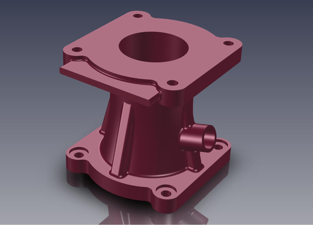
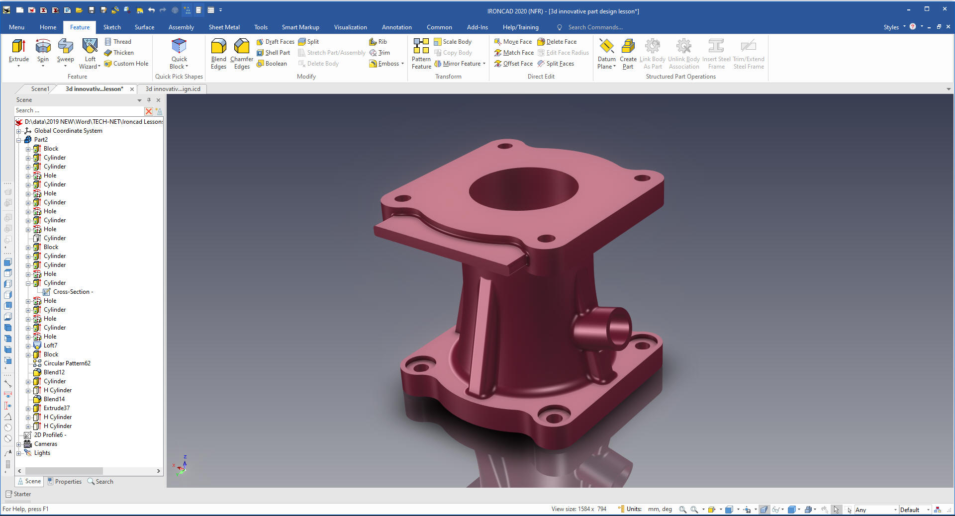
Here is our final part.
If you
would like to do this exercize here is the AID (Associated
Information Document) no drawing done here.
It is
very important that you look into how you or your engineers are
creating the parts. Streamline Sketching and Feature Based Modeling
is easy to learn and implement. It, alone, will increase
productivity 10X. Now, IronCAD with its unique integrated
history/direct edit functionality can increase your productivity
another 5X or more with changes! Again, time is money in
engineering.
More on Streamline Sketching and Feature
Based Modeling.
To experience this increased level of productivity, please download
IronCAD for a 30 day evaluation. Legacy data is no problem, IronCAD
can read the native files of all of the popular programs. IronCAD is
a great replacement for the subscription only Autodesk and PTC
products.
Give me a call if you have any
questions. I can set up a skype or gotomeeting to show this part
or answer any of your questions on the operation of IronCAD. It
truly is the very best conceptual 3D CAD system.