3D Modeling Techniques IRONCAD vs Creo Lesson
Six 3D Modeling Cannot Be This Convoluted StreamLined
Sketching/Drag and Drop Modeling
When I introduce IronCAD's very
flexible design paradigm I have a hard time to get the Pro/e clone
users, like Solidworks and other programs, to understand the drag and
drop design process.
Download IronCAD/Inovate and
follow through the lesson. Give it a try, this is a fully functional 30 day
evaluation with all of the native translators so you have access to
your legacy engineering information.
Many of these modeling techniques can easily
be implemented even within the most Solidworkish of systems. I call
it Streamlined Sketching and Feature Based Modeling. Please review a
few of the above IronCAD vs these other systems, there are some very stark differences.
Advanced 3d Modeling Tutorial in Creo Parametric - 19
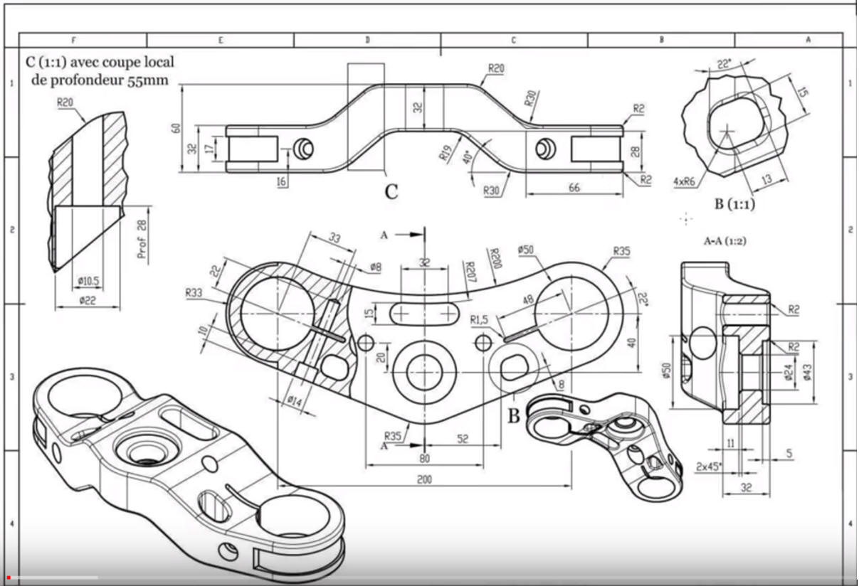
Here is the drawing so you can create this part. You can also
use the video for more detail.
While creating 3D models from drawings is the very best
way to learn 3D CAD and maybe some design techniques it does not
expose the designer to the design flexibility necessary in design. IronCAD is all top down due to the single model environment.
Creating mating parts is a cruise. But modeling is just one aspect of a
well designed productive 3D CAD system.
Creo
is a marginal 3D CAD system based on the dated Pro/e history
based modeling system released in 1988. I sold Pro/e years ago
and found it not productive enough
for our engineering department. We use what we sell. That gives us
the experience to effectively support our user base.
I would do a
video, but I really am not good at it. So I will show you step by
step. I will try and get IronCAD support to create one. They are
very good. Please watch the Creo user model this part!
I was shocked that the quite bizarre process this fellow took on
such a simple part. This is suppose to be beginner training and it
shows some overly complex methods. This surely cannot be not be
representative of most users.
Realize Creo costs $2500 per years. IronCAD
is $3970.00 for the perpetual seat. One and a half years you own the
program and it is good until MS creates a incompatible OS. Now we do
have a rental program at $1500 per year.
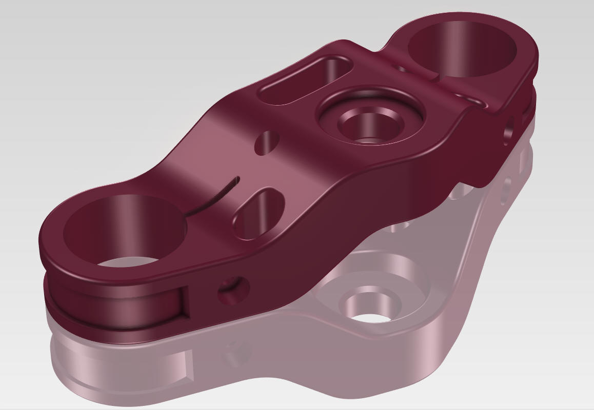
This IronCAD exercise took a few minutes and allows
for faster and much easier modification. Again these exercises turned
into a study of modeling techniques even though most of this model
is Feature Based Modeling not available to most of the Solidworks clones.
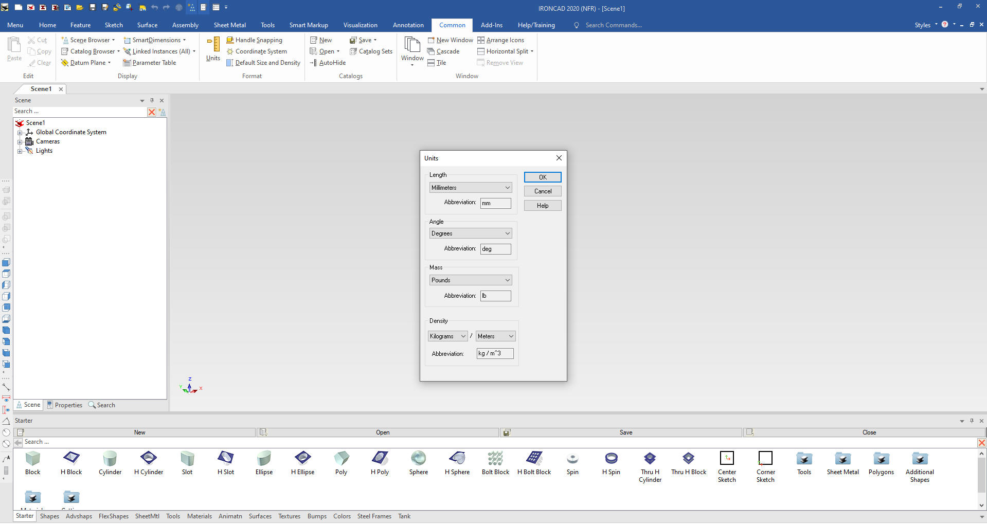
Here is IronCAD. My default is inches,
so we will set the units to mm. Let's get started.
StreamLined Sketching/Drag and Drop
Modeling.
We will first create the model using
StreamLined Sketching and Drag and Drop Modeling using IronCAD's
unique drag and drop from catalogs functionality.
But Feature Based Modeling does not
require the use of primitive or intellishapes it is based on
understanding the basic shapes of the part. You will see me use that
process in the next StreamLined Sketching Only lesson.
We are going to sketch the basic shape.
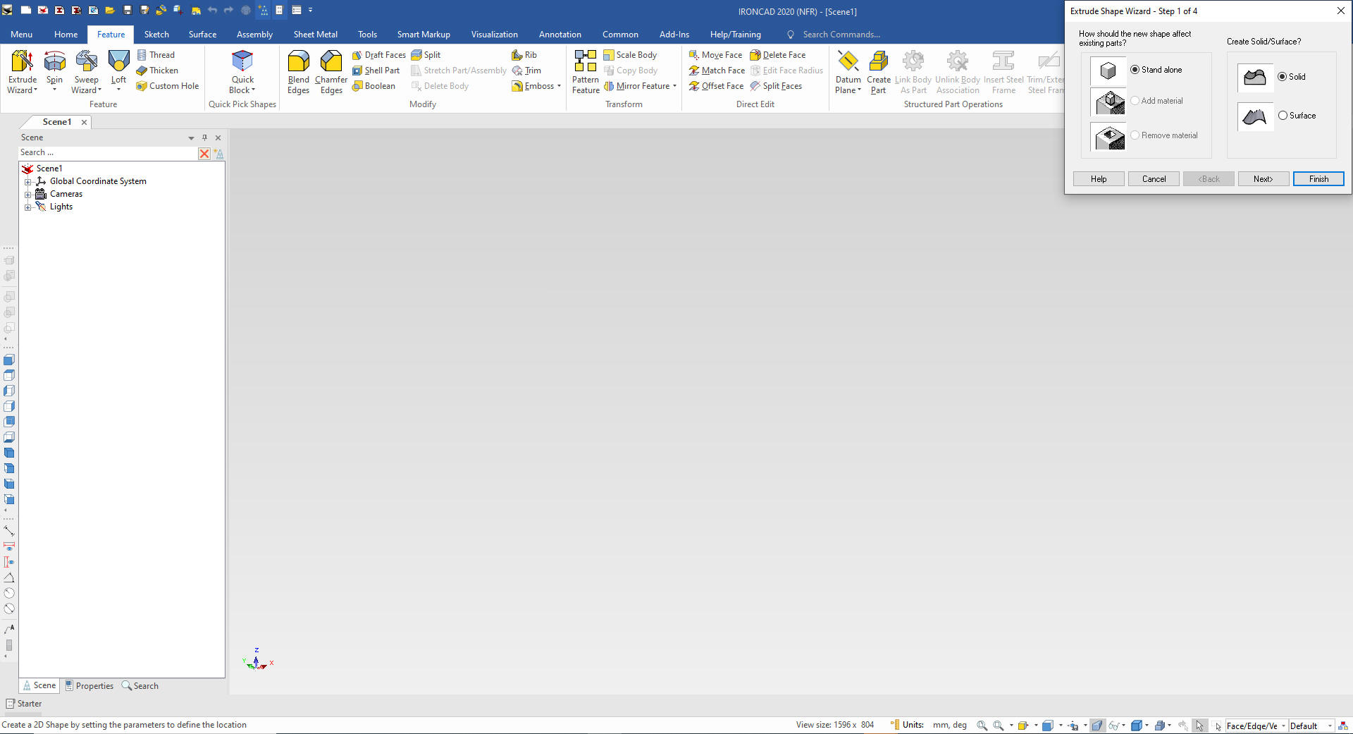
We will use the Extrude Wizard that automatically creates the
extruded part when the sketch is complete. We will select Extrude
Wizard and a dialog box will come. In this case there is no other
features so it will know we are going to create a standalone part.
The Extrude Wizard allows us to set the
depth of the extrusion. So it eliminates a few steps. It is mostly
used for top down design by creating mating or common features on
new parts.
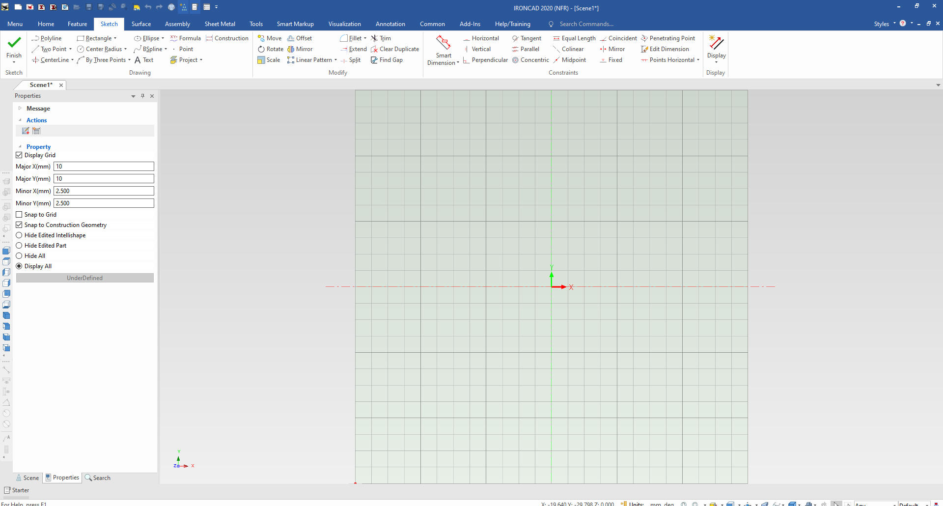
I will put a sketch plane in the scene at X0Y0Z0.
Note: Why does IronCAD
call it a scene instead of a workspace? IronCAD was first released
as a graphic design program called Trispectives. It still has much
of the graphic design functionality. It truly is a wonderful mixture
of professional 3D CAD and graphic design, which puts it in a much
more flexible category as compared to the very mechanical
engineering focused Solidworks clones.
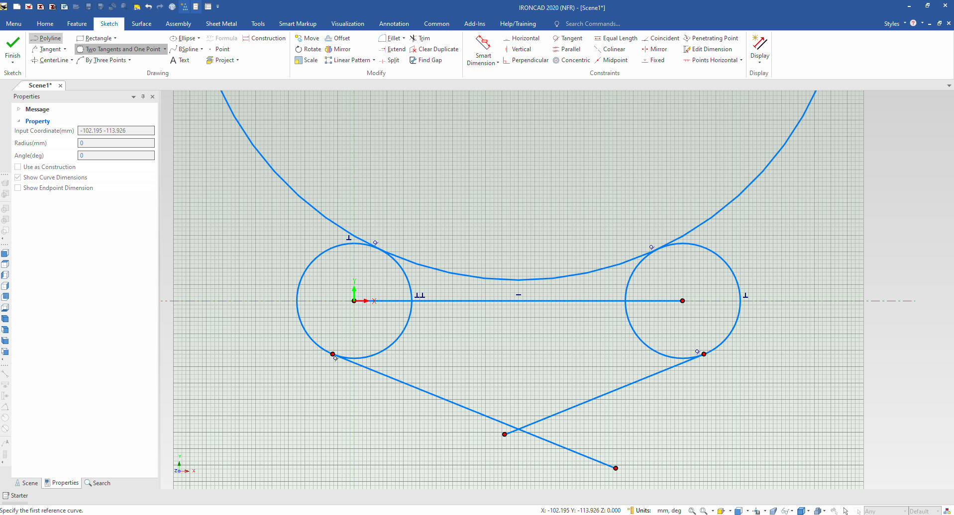
In a sketch
based system it is much more convenient to set the center point in
the sketch around X0Y0Z0 as shown in the Creo presentation. I am
going to purposely locate it arbitrarily in this case at the center
of the left circle.
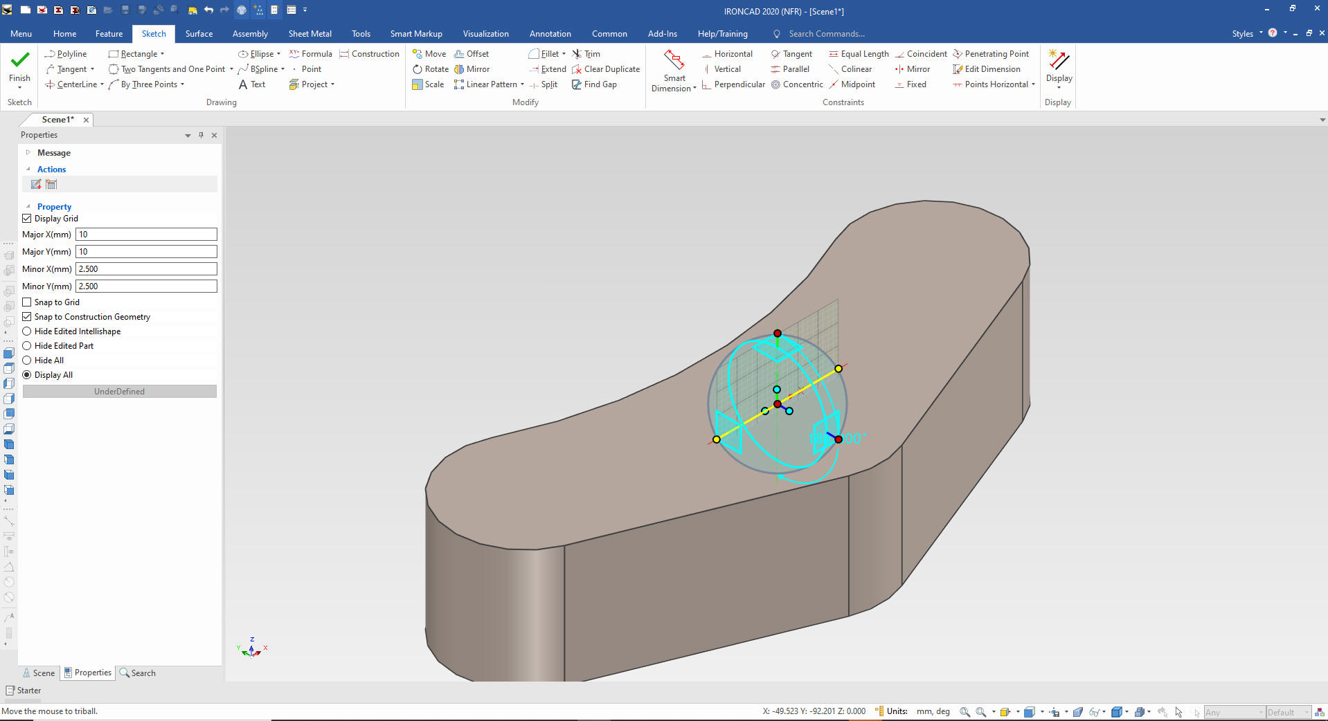
I create the first circle using the
right mouse button and it prompts me for a radius 35mm, I put in the
line using the right button and prompts me for a length 200mm (I
commonly use graphics for construction), I create another circle. I use
tangent to circle command with the right mouse button and it prompts
me for slope and length, I leaves me in the same command an I create
the second line. I create a circle with two tangent and a radius
200mm for the top radius.
You can see the results.
The Creo presenter takes over 3 minutes to create this sketch, it
starts at 6:22 ends at 9:35. It is only 5 entities plus my
construction line. I do not throw
in some graphics and constrain them I define them as I put them in.
This is what I call StreamLined Sketching and Feature Based
modeling.
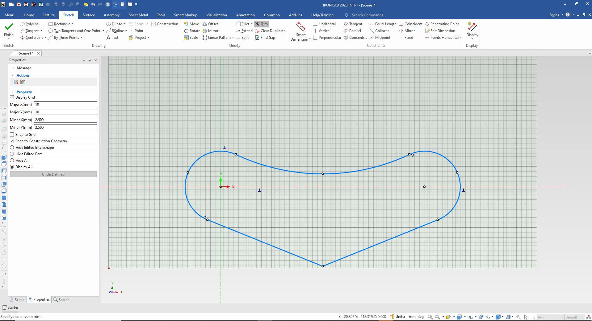
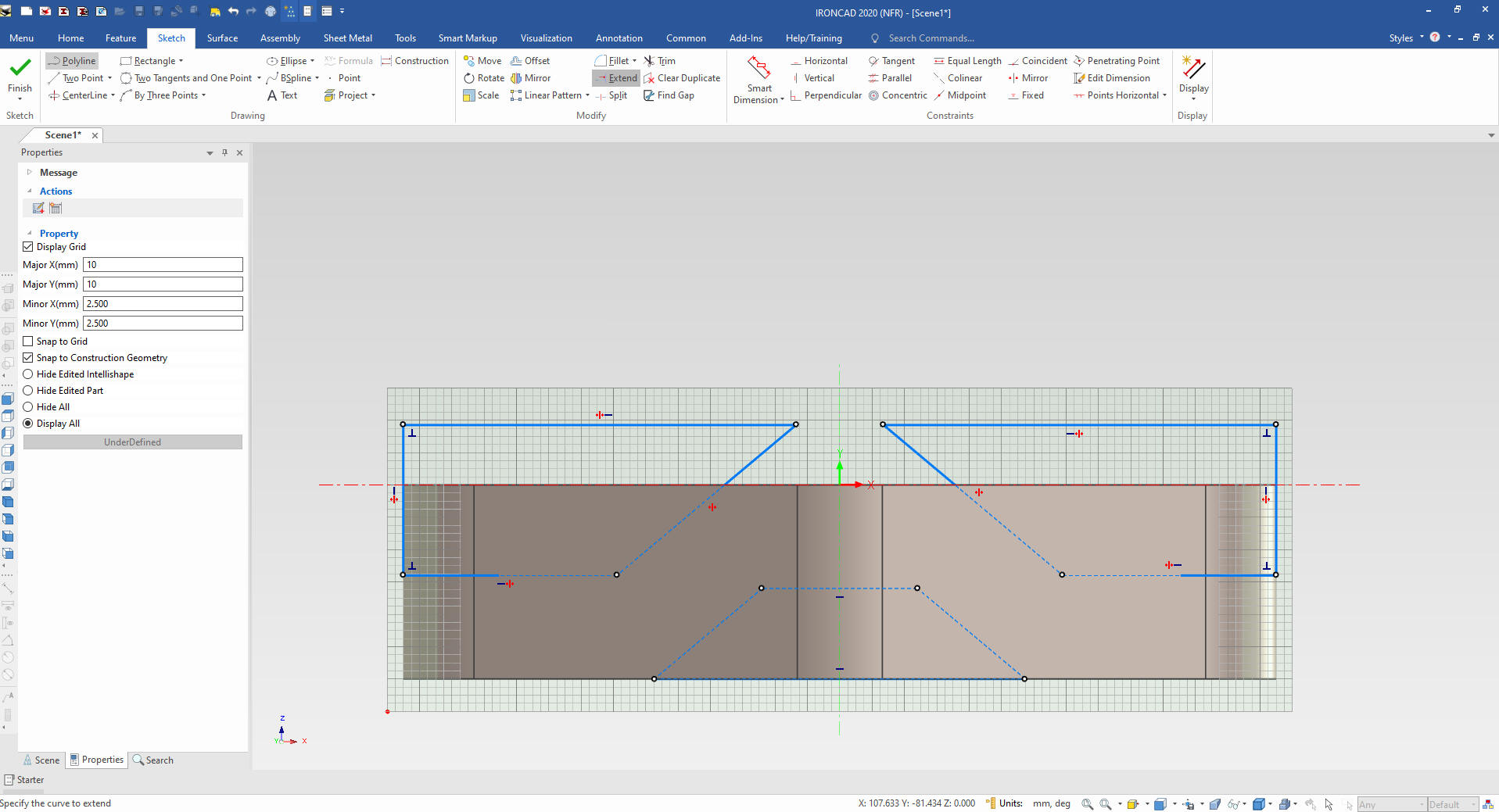
We just delete
the one entity used for construction and trim/extend the necessary features
and were are done with our sketch. I do not put in the blend on the
bottom I will put it in later.
I select okay
that exits the sketch and we have our feature. You can see some
handles available, so you can modify the feature directly.
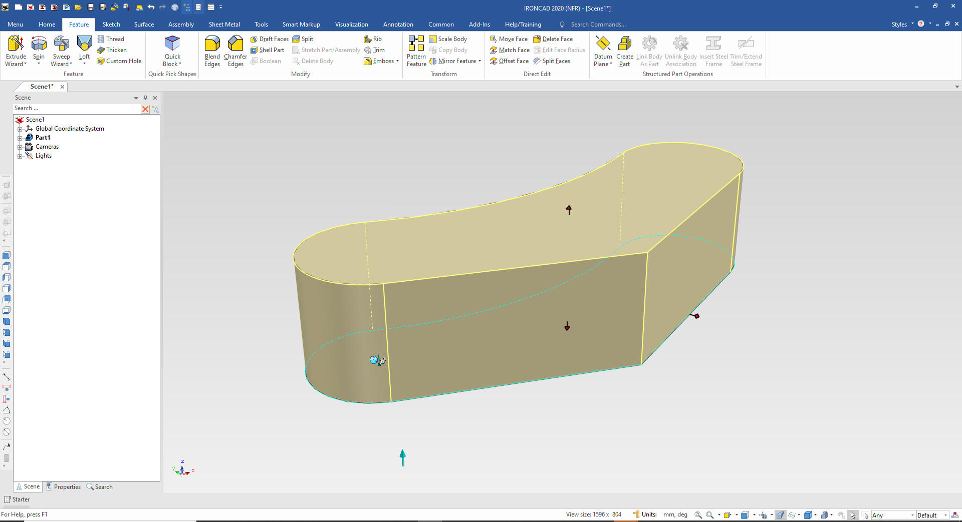
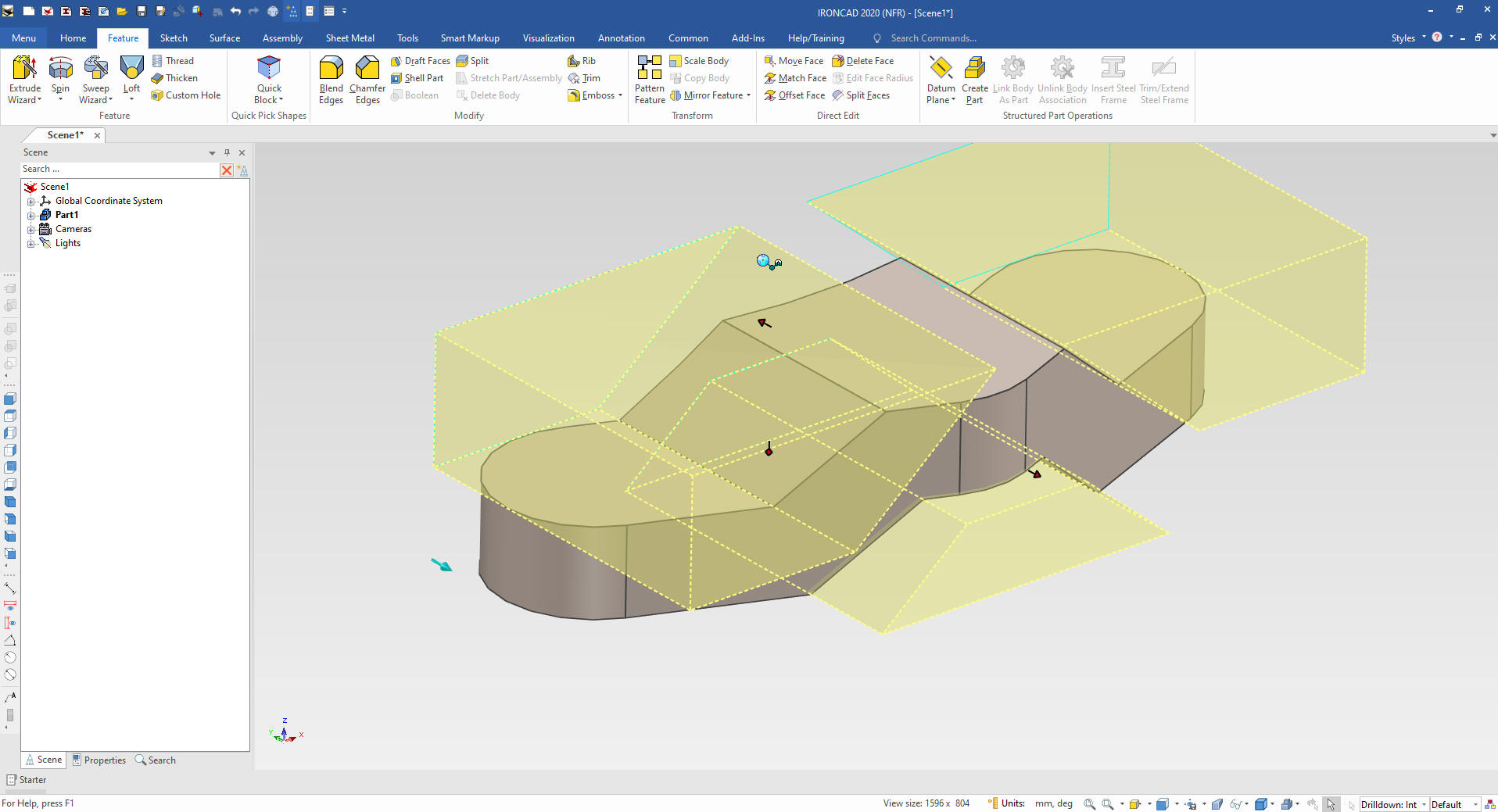
We will put the blend in and set up
the sketch plane for the next step.
Again using the Extrude
Wizard we create a sketch plane at the center of the shape and
rotate it with the Triball. The Tribal is used to manipulate
sketches, features, parts and assemblies plus many other uses. We
will set it to remove.
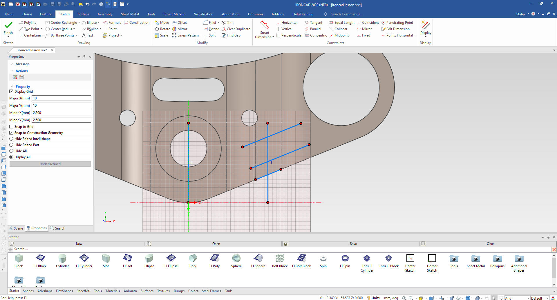
We can now create our sketche.
We create the entities by projection, defining the lengths, trim and/or extend. No
constrained dimensions.
Note: Since the planes are not part
of the history and become part of the feature, we use them as we need
them. I just create a sketch anywhere I want. I do not have to be
concerned about sketch placement or symmetry. This freedom is
available due to the SME (Single Model Environment).
We select okay and pull the cut to
include the existing feature.
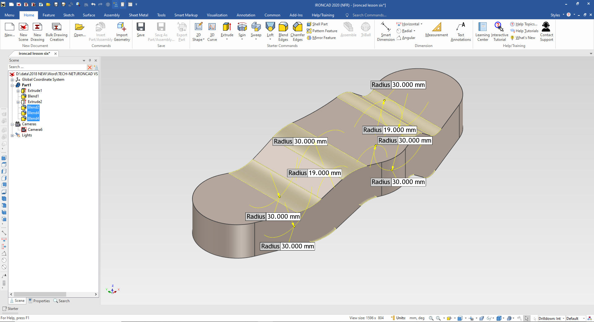
We put in the
major blends.
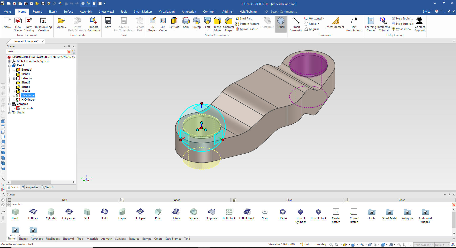
We drag and
drop a hole cylinder to the center of the relative feature size it
and using the Triball we link another at the other center. Linking
allows changing one and the other also changes.
Note: You
will notice I have turned on the catalog. I usually design with it
hidden but for our lesson we will pin it open.
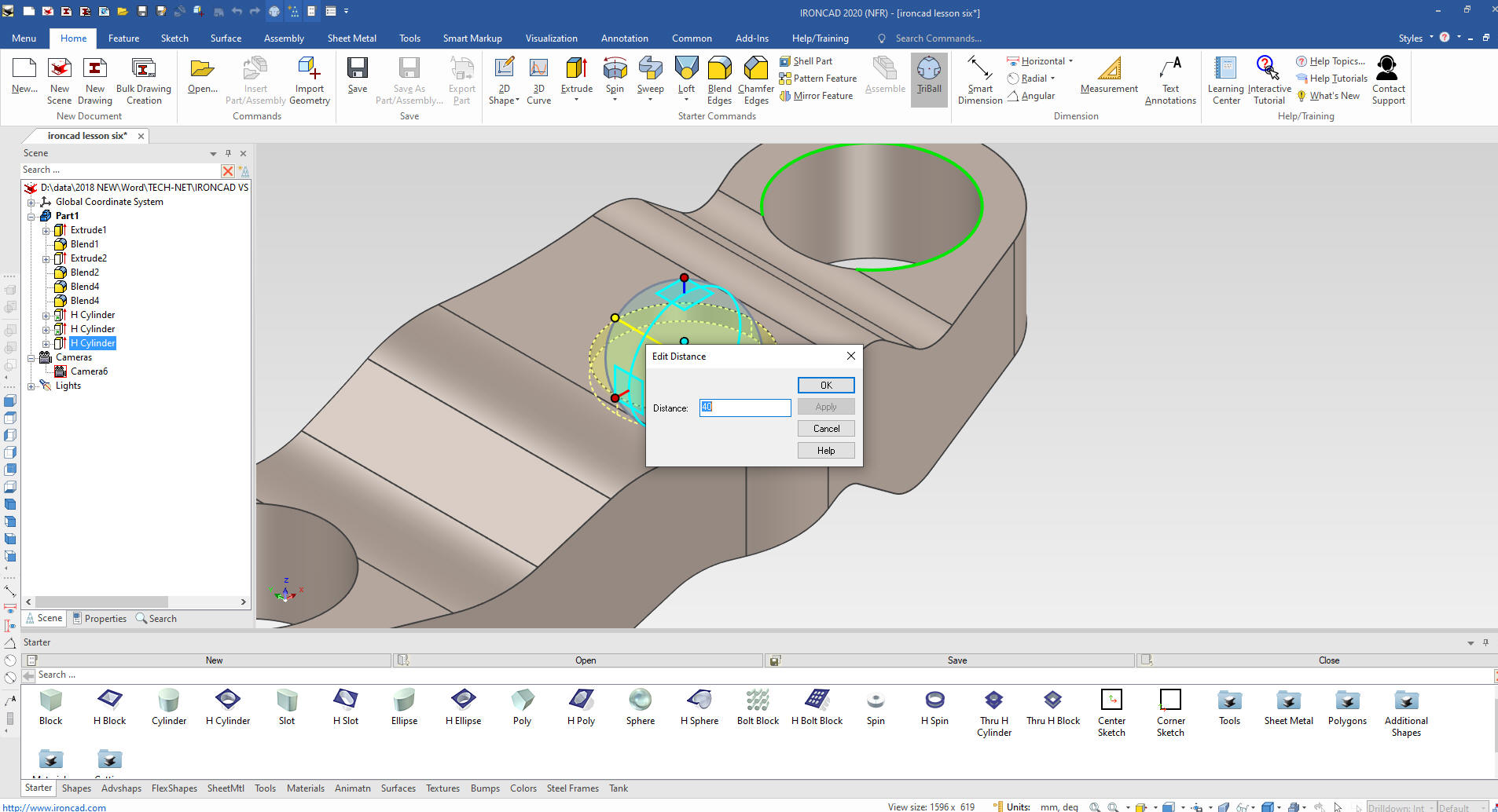
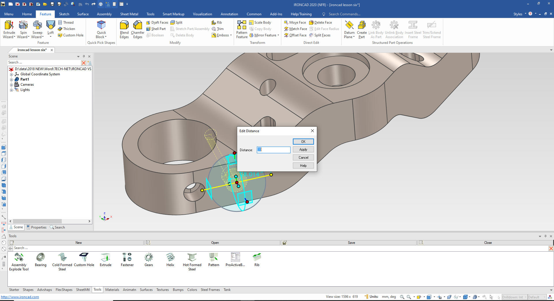
We
drag and drop a hole cylinder to a mid point on the top face and
size it with the handles. We use the Triball to locate it from the
center of the existing hole using the Edit Distance from Center
command.
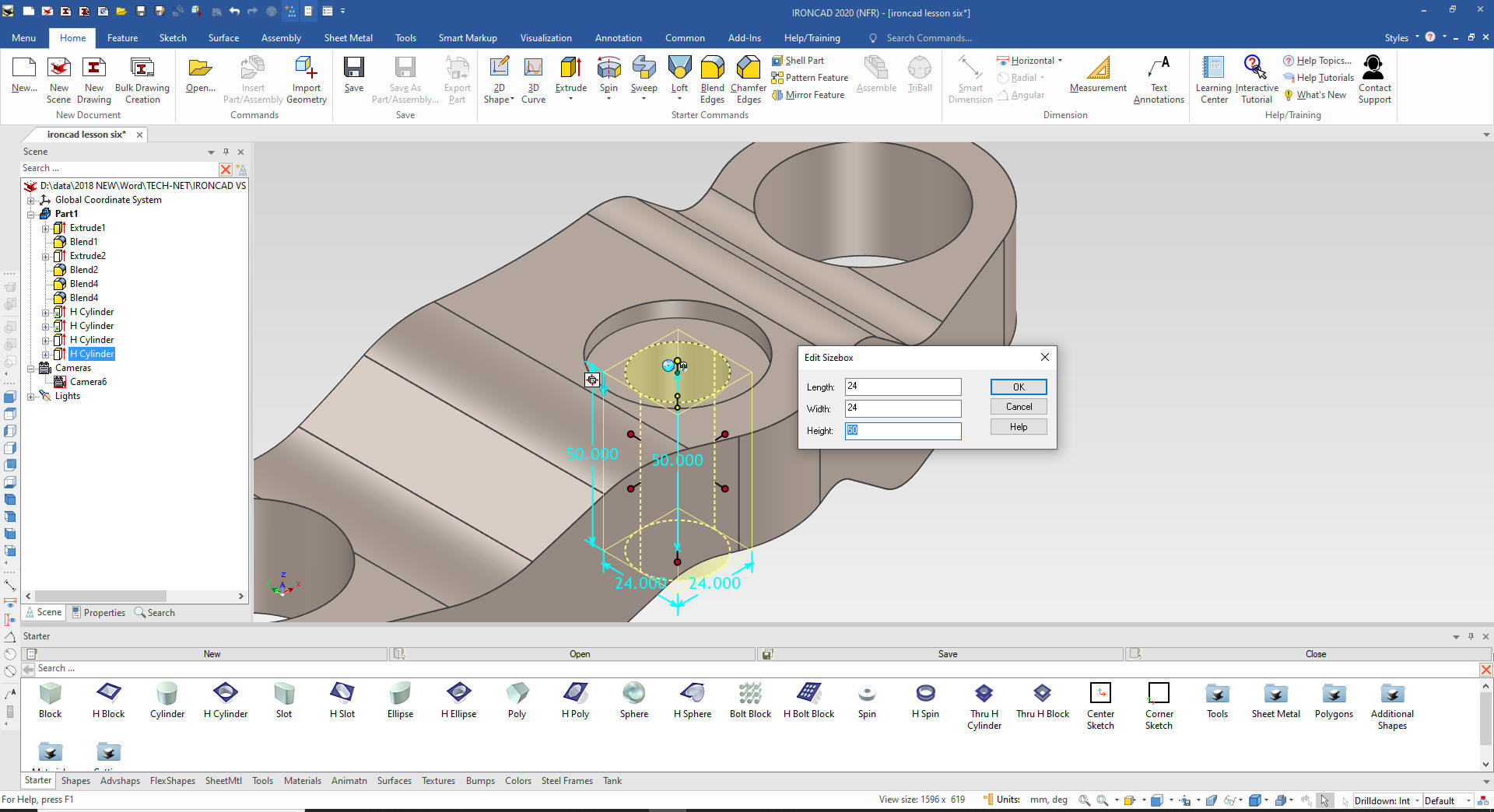
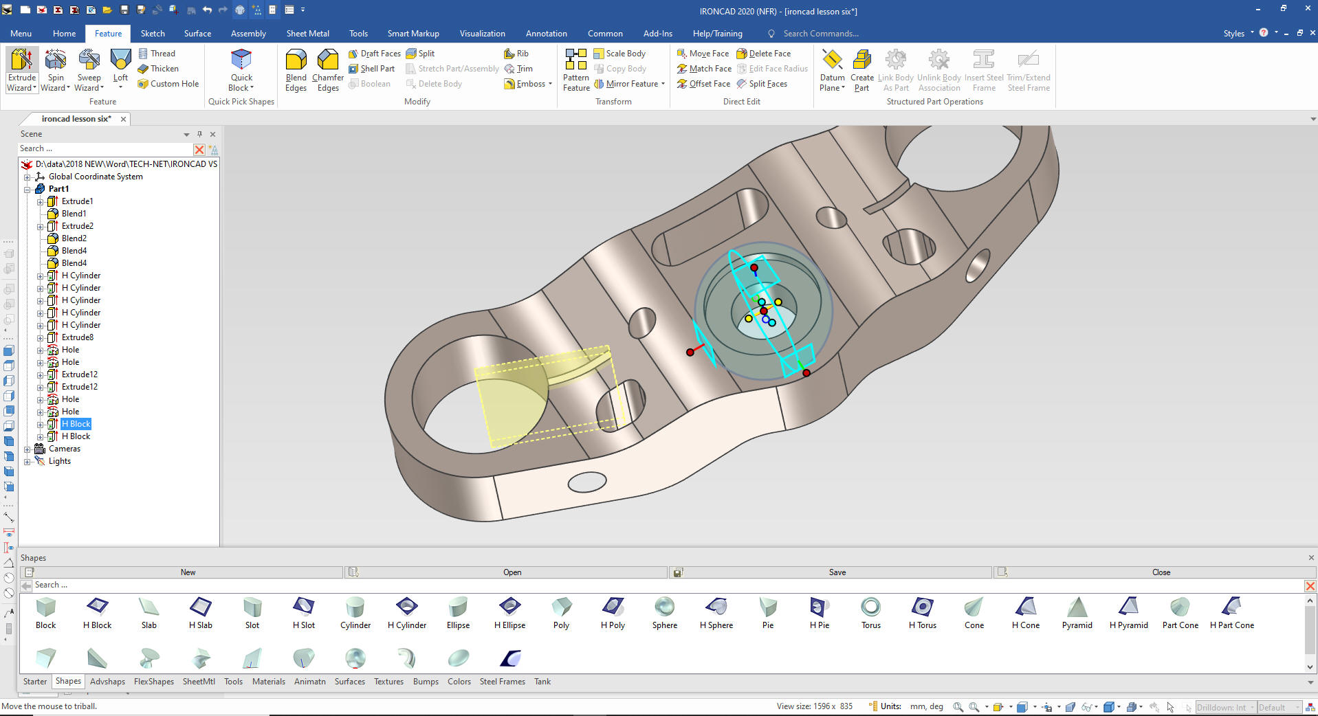
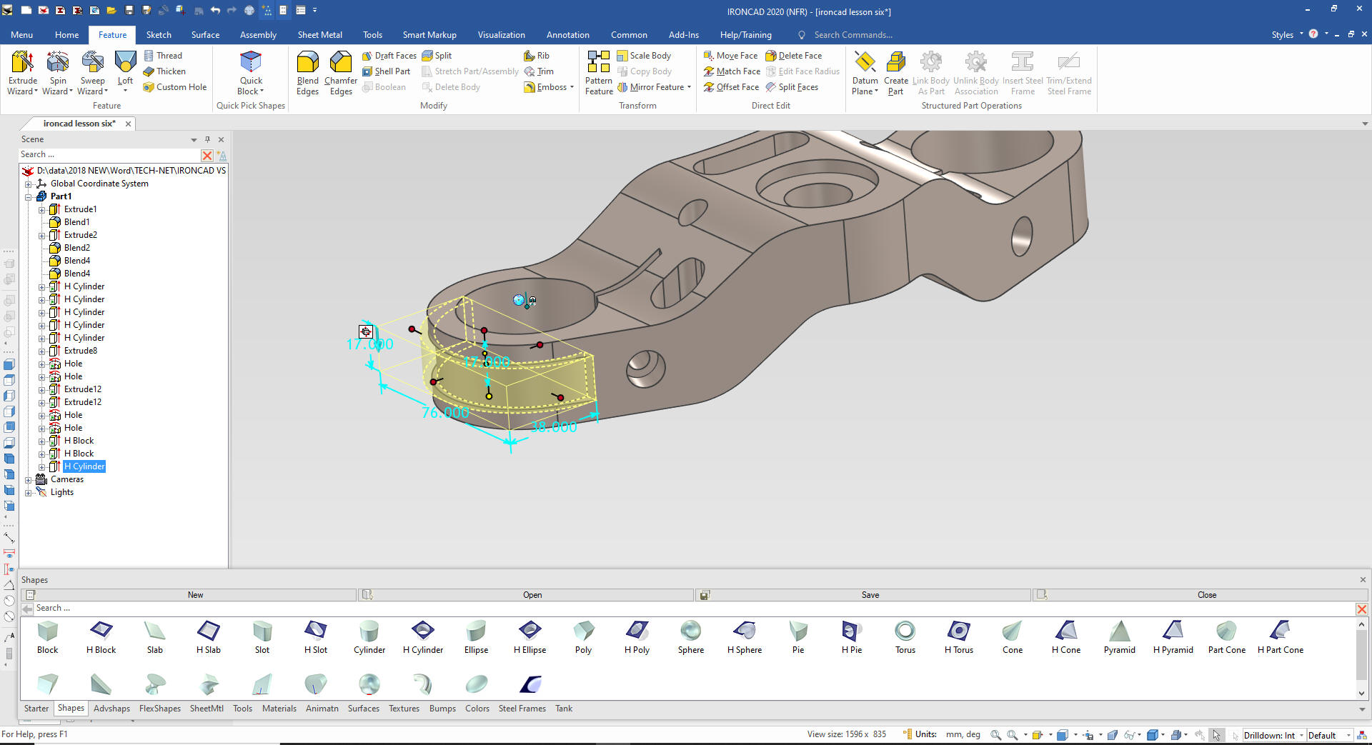
We drag and drop another hole cylinder
to the center of the counterbore and size it.
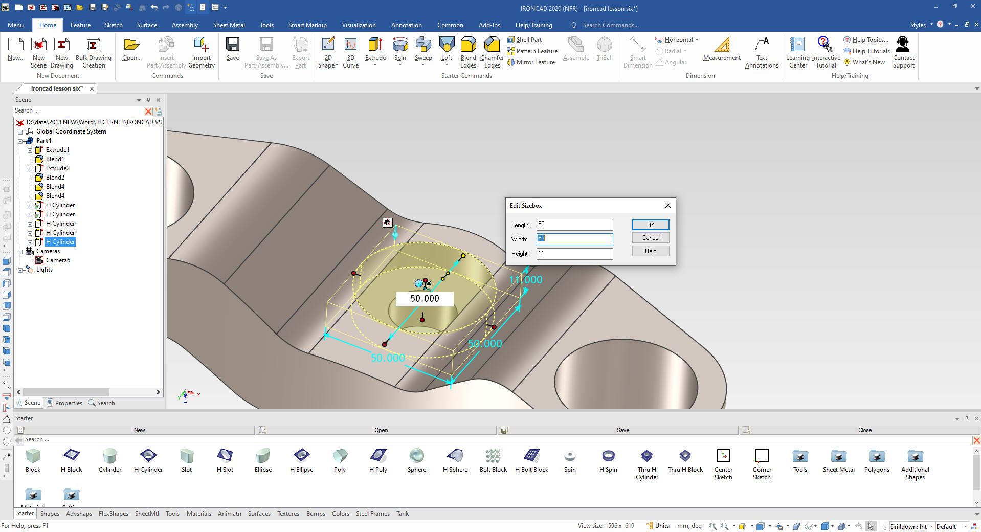
We
drag and drop a hole cylinder at the center of the existing hole and
size it.
This simple hole seems to be challenging for the
poor Creo presenter you can see this on the video starting at 21:00
and ending at 23:28. I promote feature based modeling! We are
creating holes, why is he doing a constrained sketch and a revolve.
Creo has hole commands. He didn't show pulling it through the
blends. It seems like you would just edit the revolve sketch a bit
deeper.
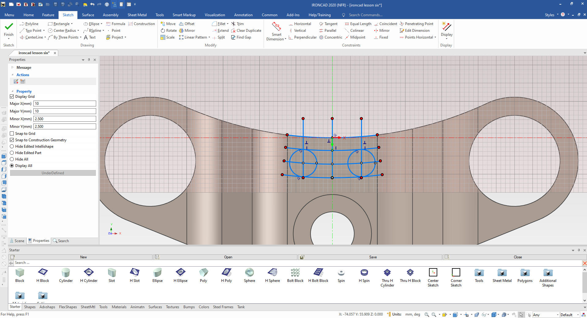
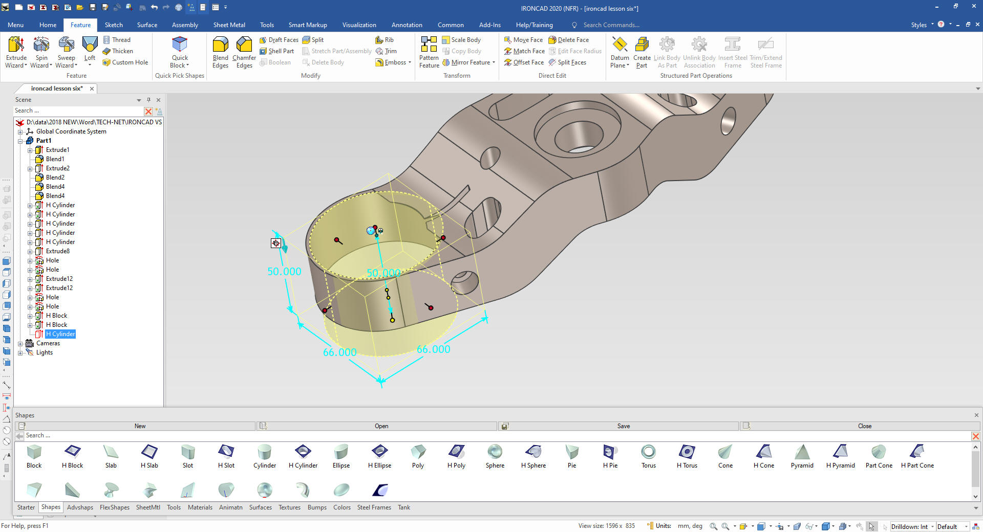
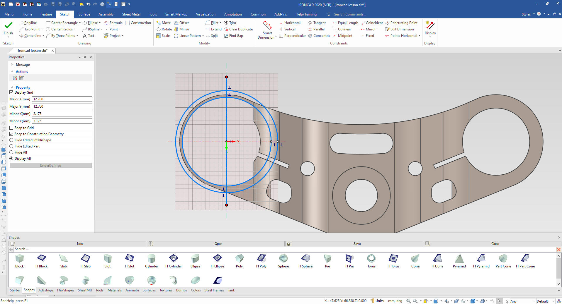
Using
the Extrude Wizard we create a sketch plane on the top face. We
project the top edge and create 3 more offsets of the arc. We create
a centerline and do an offset on both sides. We they put in our
circles at the pertinent intersections.
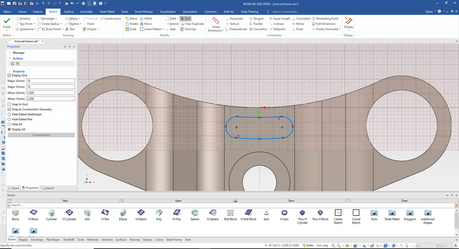
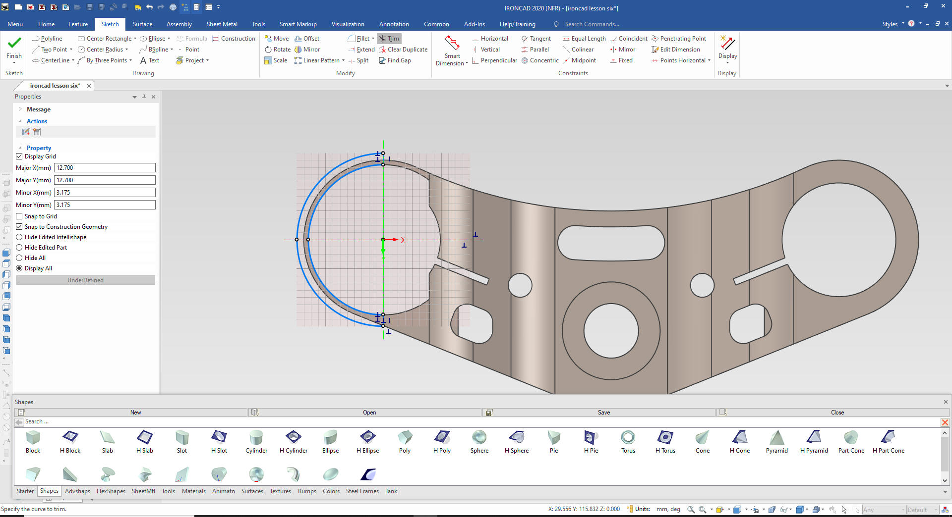
We
delete the construction entities and trim the others.
The
Creo race track feature is very clever. Who da thunk it?
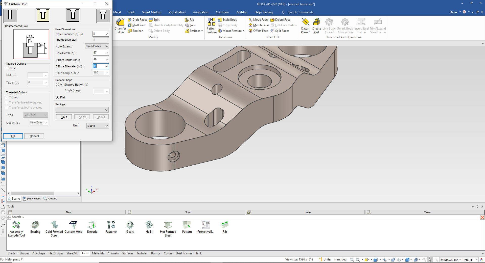
We
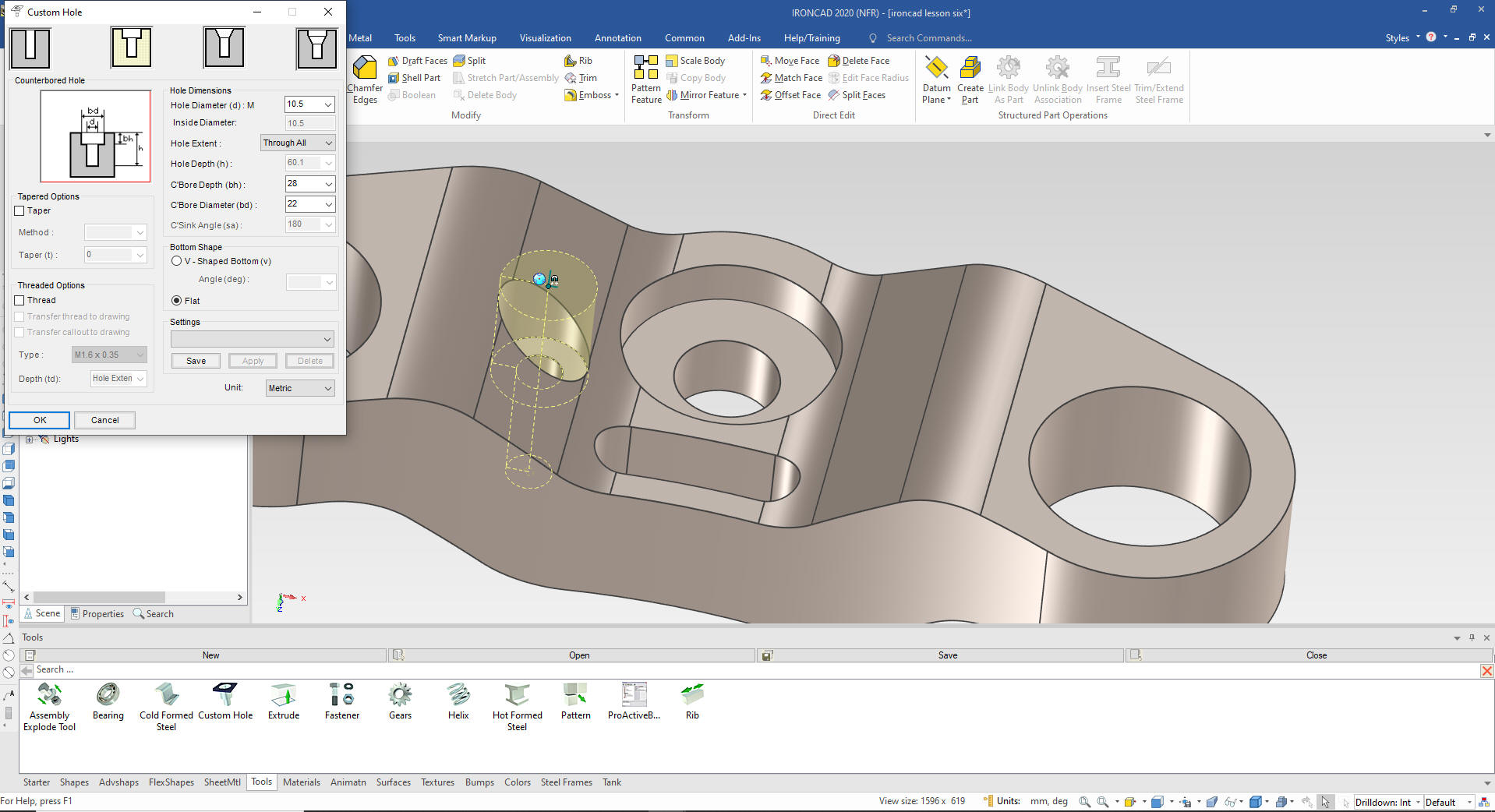
will drag and drop a hole from the custom hole tool on the face of
the large hole feature. We select Counterbore and set the size. We
will locate it using the triball "Edit Distance from Center".
Note: I really don't know what the Creo presenter is trying to
do here. It starts at 24:20 in the video.
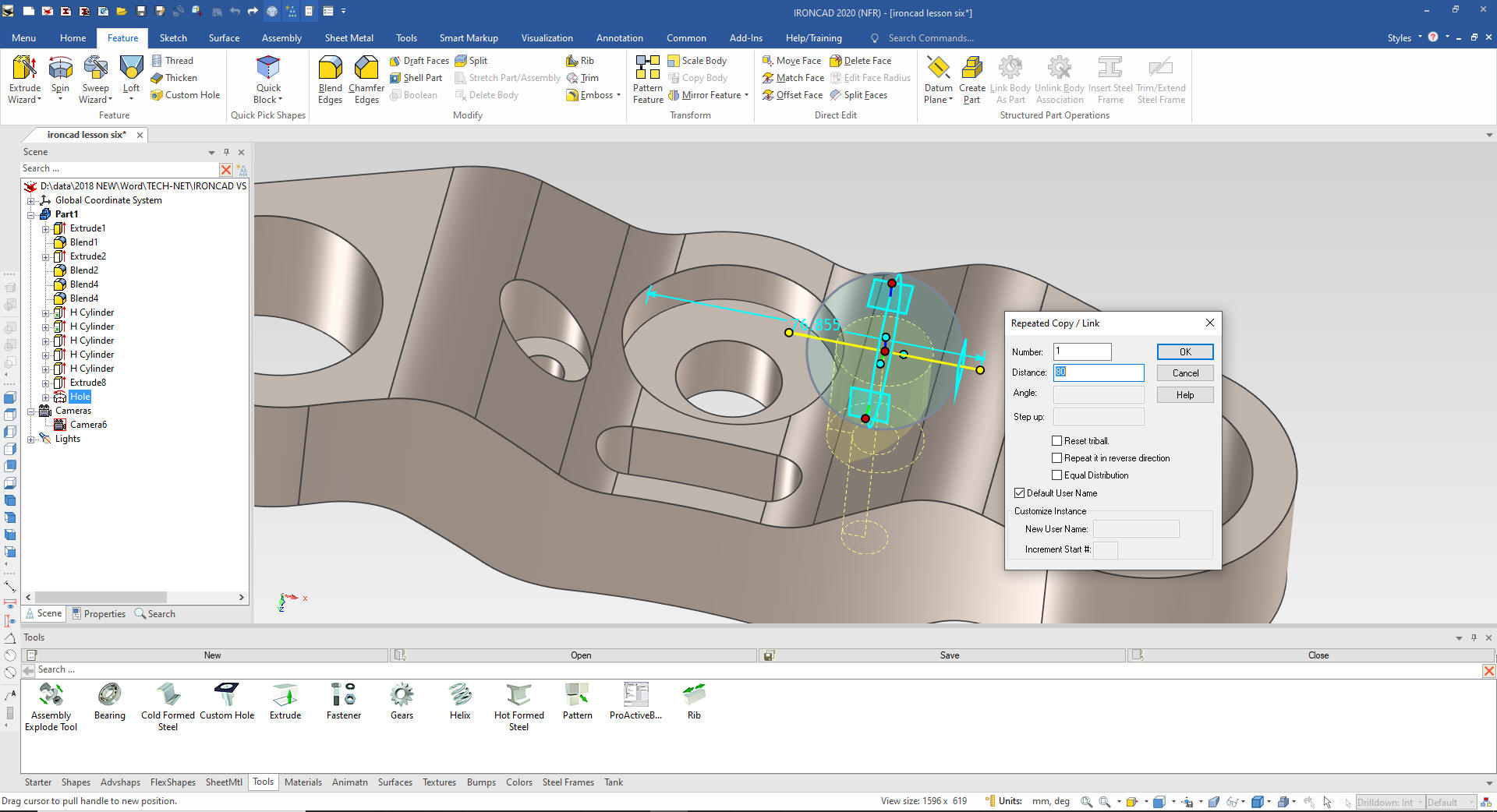
Now
we will use the Triball to link the second hole into place.
Again using the Extrude Wizard we create a sketch plane on the
top face. We create a center line and project the relevant edge. We
just create a few offsets.
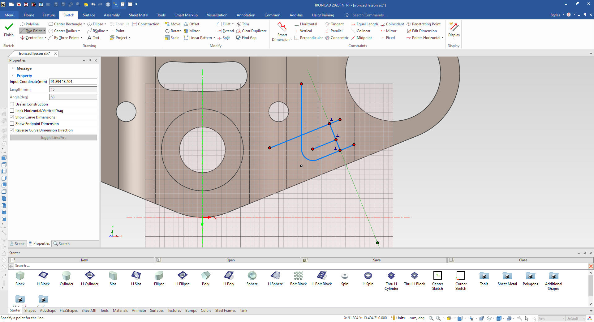
We
create the fillet and then create a 13mm line, IronCAD automatically
recognizes parallel lines and perpendicular lines.
We
delete the construction line and trim the entities and add the
fillets.
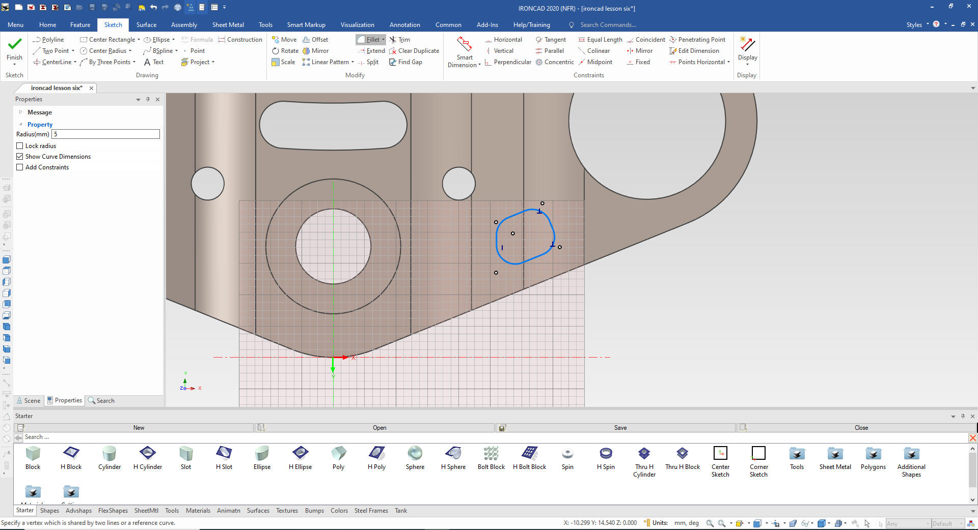
We
select finish and the extrusion is automatically made. No need to
select an extra extrude profile command.
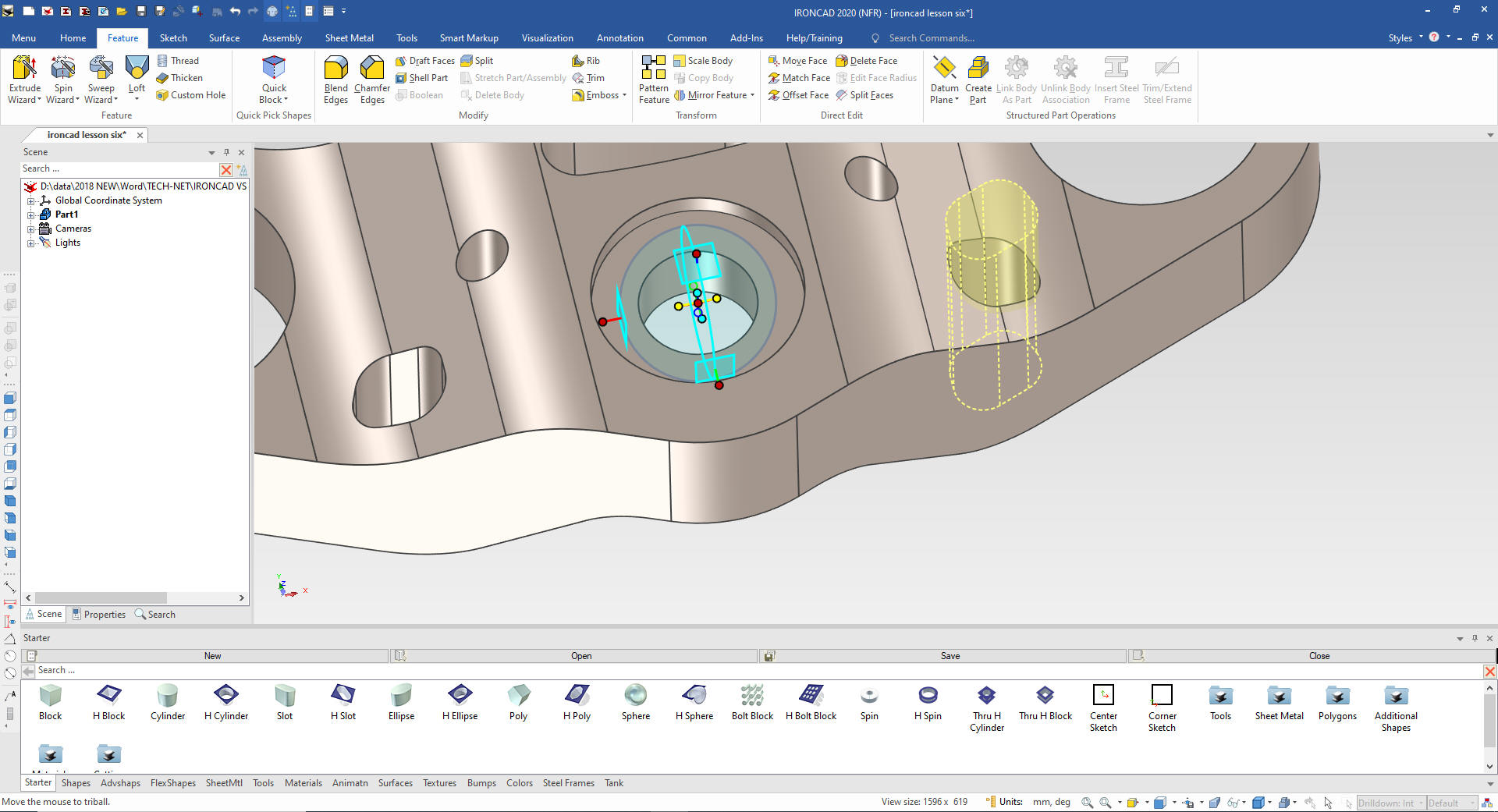
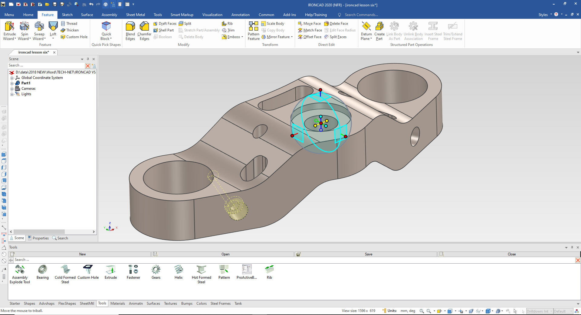
We pull it through
if required. We turn on the Triball and select the space bar that
allows us to move the Triball only, it also turns it back on. We
move it to the center of the hole as shown and the inside handles
will define the mirror link.
Note: The Triball functions as a
temporary plane. This is so much more productive. Just think about
it if you are Solidworks clone user.
We
will go to the custom hole in the catalog insert a counterbore hole
on the relative face and locate it on the mid-point of the tangent.
They define basic hole incorrectly. You would have a hard time
inspecting it.
We use
the Triball to move it into place.
We
turn on the Triball and set it to move only the Triball. We center
it on the hole. Now the Triball is in the orientation of the hole so
we set it to global coordinates. Turn it one and mirror link the
hole.
Now for the slot we just drag a hole block on the face and
locate and size it.
We
again use the Triball to mirror link the feature.
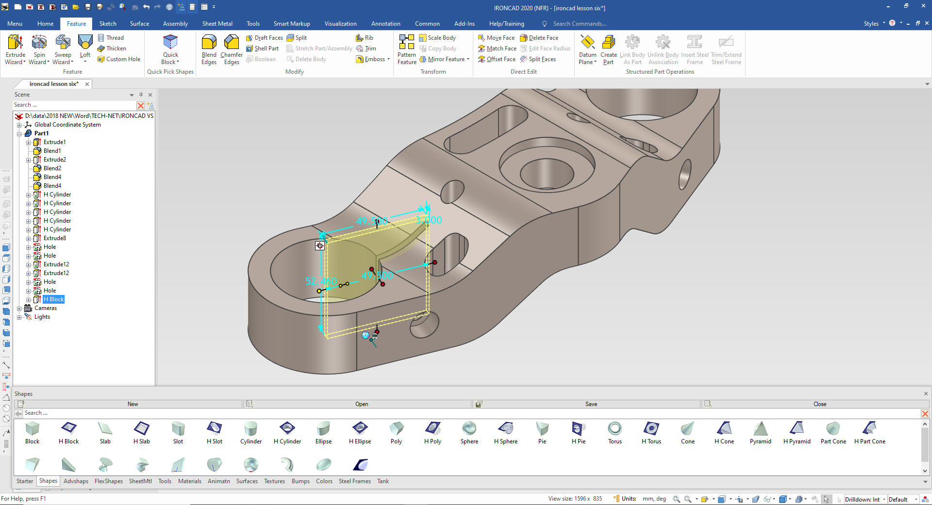
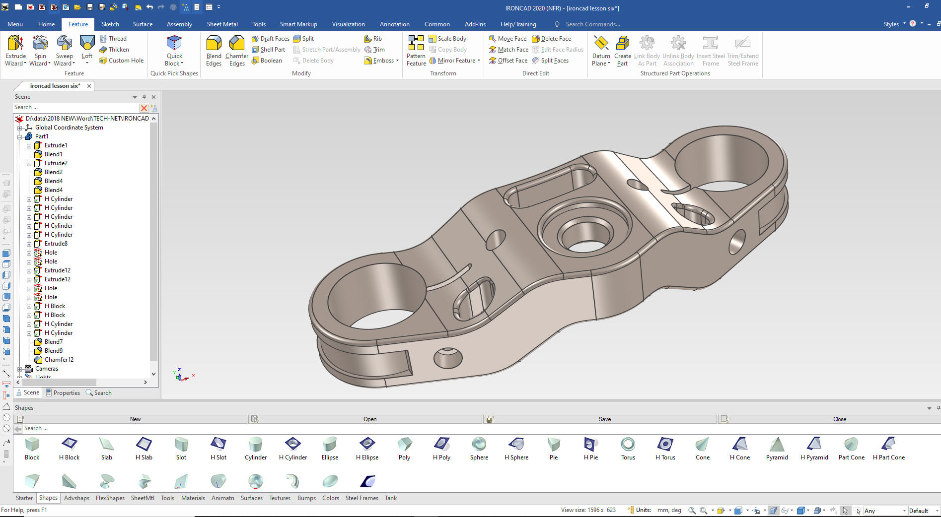
Now
for the outer trim. We drag and drop a hole cylinder on the center
of the existing hole and size it to ID of the feature.. There is a
method to my madness.
All of the drag and drop features (Intellishapes) are based on
sketches. We will turn on Edit Cross Section and edit the
Intellishape.
Give me a call if you have any
questions. I can set up a skype or go to meeting to show this part
or answer any of your questions on the operation of IronCAD. It
truly is the very best conceptual 3D CAD system.
If you are interested in adding professional
hybrid modeling capabilities or looking for a new solution to
increase your productivity, take some time to download a fully
functional 30 day evaluation and play with these packages. Feel free
to give me a call if you have any questions or would like an on-line
presentation.