IronCAD vs Fusion 360 Lesson 9 3D Modeling Techniques Defined Streamlined Sketching/Feature Based Modeling
The modeling technique is
hugely responsible for the level of productivity. Those of you that
are only trained in the sketch, sketch, constrain, constrain world
are truly limited by not using the freedom of Streamlined Sketching
and Feature Based Design,
that is available in even the most Pro/e-ish of CAD systems. If your
designers are designing in these very unproductive and time
consuming processes it might be time to review your standard design
processes. Don't have any do you? When I introduce IronCAD's very
flexible design paradigm I have a hard time to get the Pro/e clone
users, like Solidworks and other programs to understand the drag and
drop design paradigm.
Download
IronCAD/Inovate and take
the one day and 17 lesson course. I get rave reviews from my new
customers. Give it a try, this is a fully functional 30 day
evaluation with all of the native translators so you have access to
your legacy engineering information.
IronCAD Self-Pace Training Course
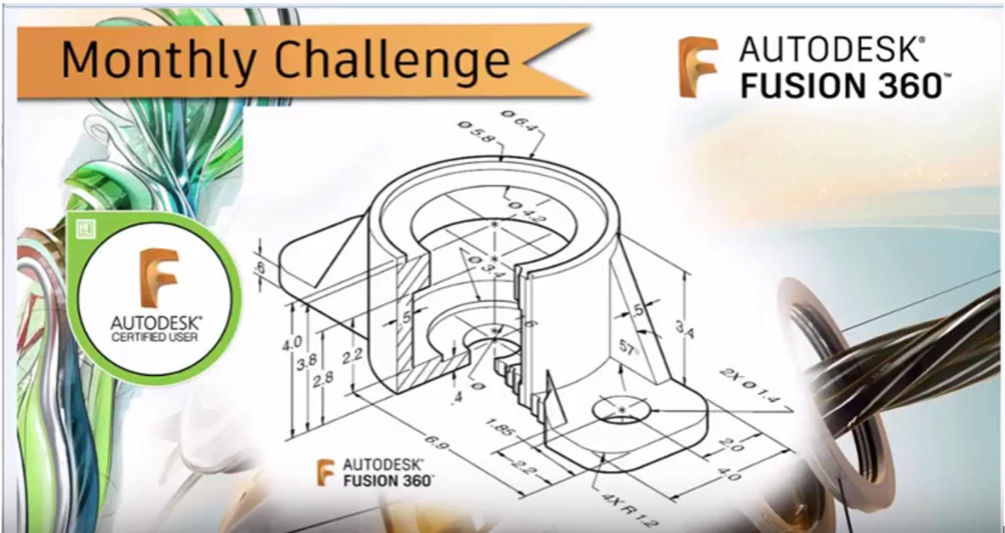
I saw the
following video challenge on linkedin and thought I would give it a
try on IronCAD. I actually did it before I watched the video, so I
did it a bit differently. This will give you an idea how different
and flexible IronCAD is compared to the conventional Pro/e clone and
to the not so conventional Fusion 360.
While creating 3D models from drawing is the very best
way to learn 3D CAD and maybe some design techniques is does not
expose the designer to the design flexibility necessary in product
design. IronCAD is all top down due to the single model environment.
Creating mating parts is a cruise. But modeling is just one aspect of a
well designed productive 3D CAD system.
I would do a
video, but I really am not good at it. So I will show you step by
step. I will try and get IronCAD support to create one. They are
very good.
I always create the part before I watch
the Fusion 360 Video, so as to not taint my process. Of course,
there are a multitude of ways to create a model. There is no right
way, just more productive ways. From what I have seen from these
very complicated processes done by the Fusion 360 fellow, it is not
just limited by the 3D CAD system.
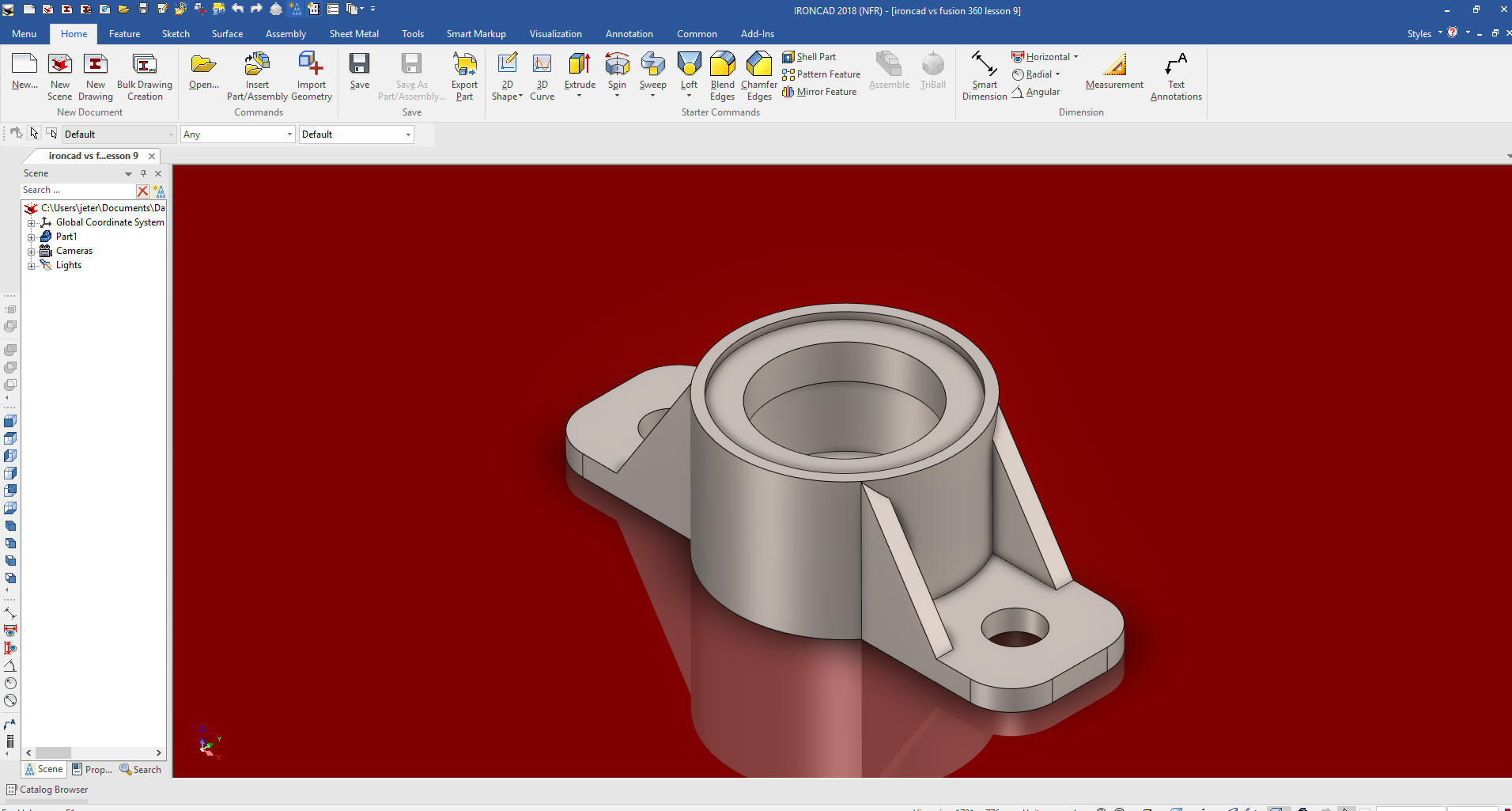
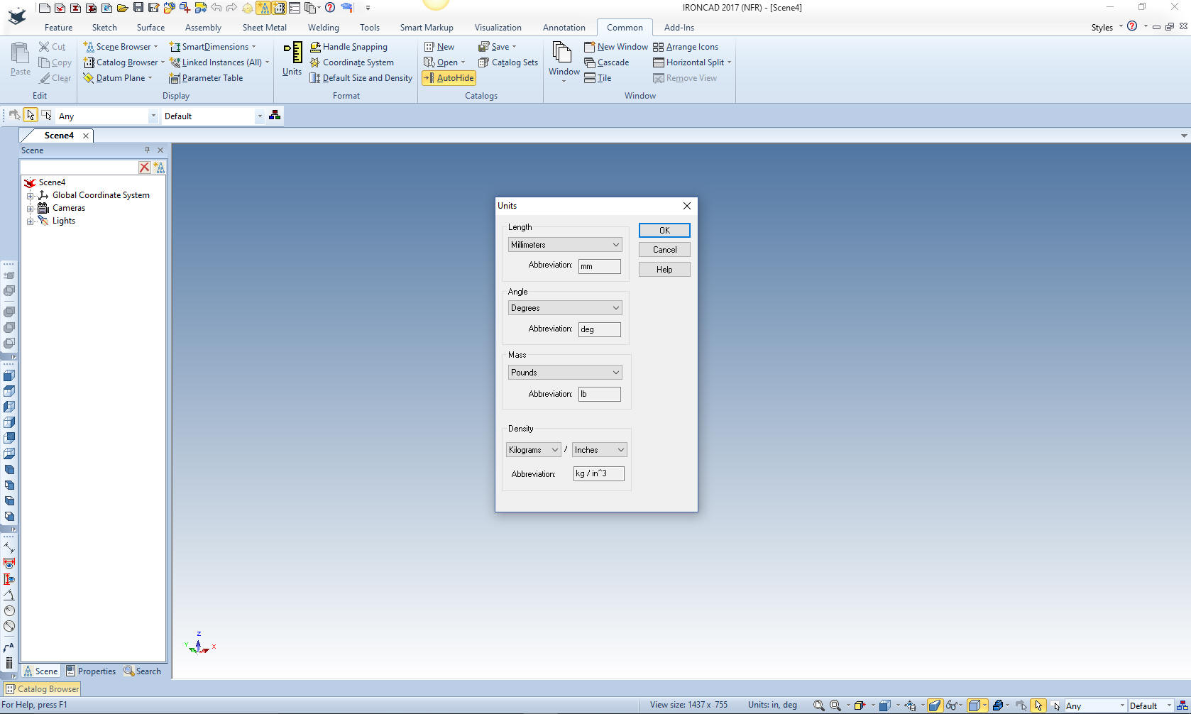
Here is IronCAD. My default is inches,
so we will set the units to mm. Let's get started.
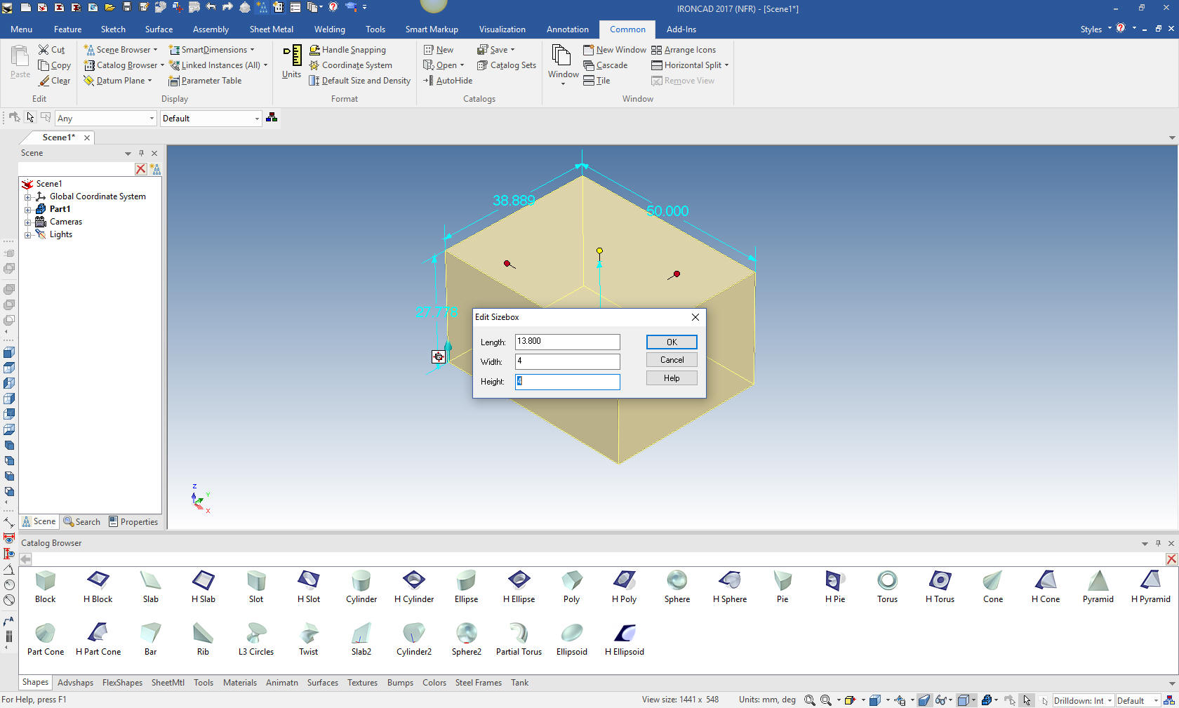
I instantly differ from the Fusion 360 presenter by dragging and
dropping a block that makes up the base of the part and sizing it.
While he is concerned about sketching shapes. I am thinking of basic
components of the part.
Why does IronCAD call it a scene instead of a workspace? IronCAD was
first released as a graphic design program called Trispectives. It
still has much of the graphic design functionality. It truly is a
wonderful mixture of professional 3D CAD and graphic design, which
puts it in a much more flexible category as compared to the Pro/e (Creo)
clones.
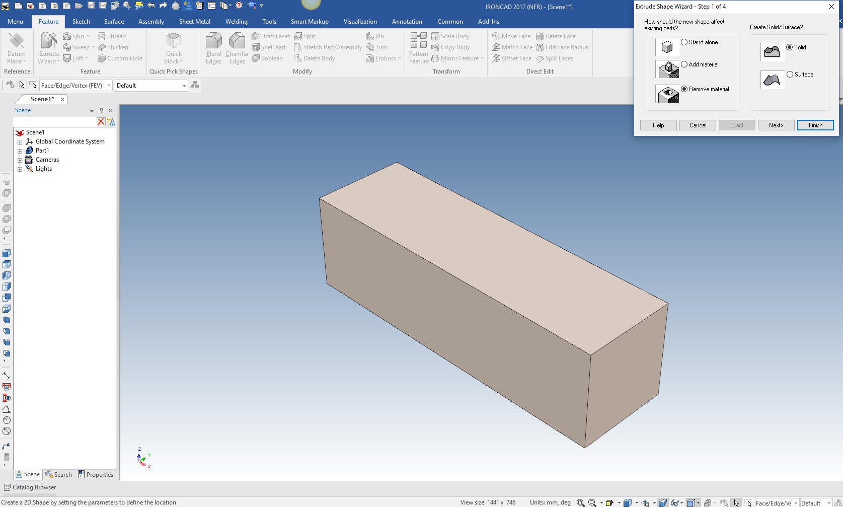
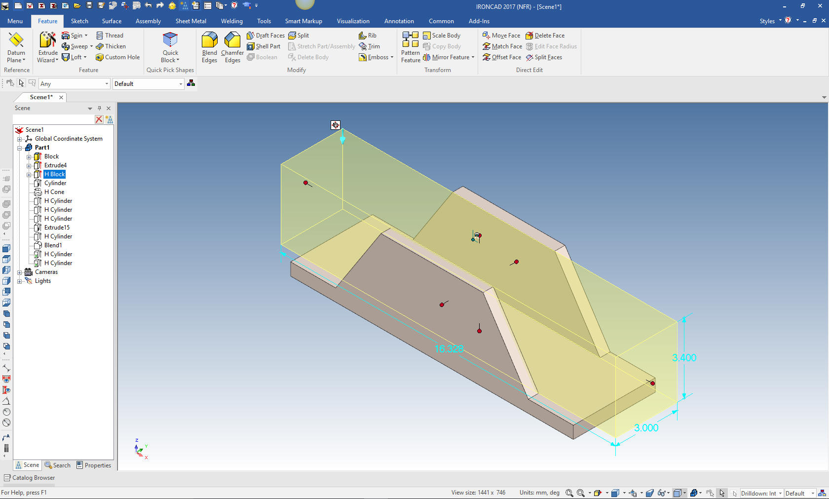
There is a time for sketching. I could drag and drop as negative
shape and manipulate it, but a sketch is the optimum next step. With
the extrude wizard (Probably the next most used tool after drag and
drop) we set up a 2D profile to create our sketch.
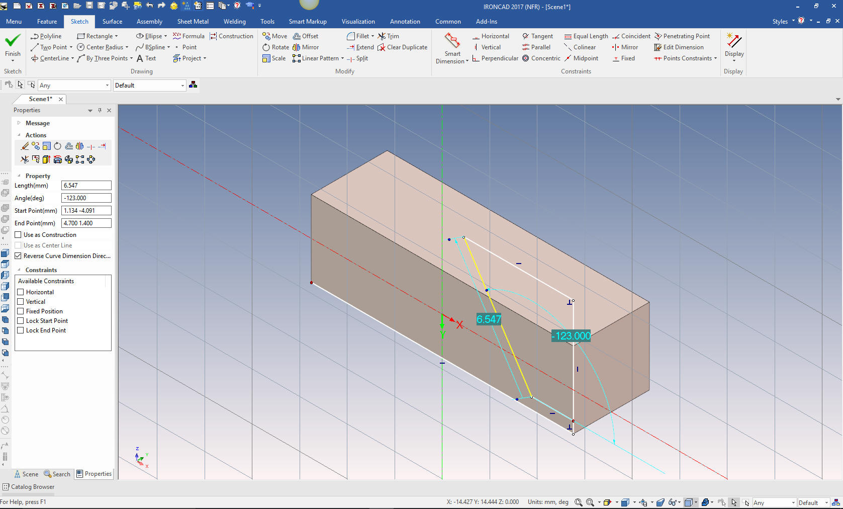
I don't sketch like the Fusion 360 presenter. I was a mechanical
draftsman and we drew by sliding triangles or using a drafting machine (creating
horizontal and vertical parallel lines) this was continued into the
early CAD systems. I have adopted this practice in my sketching and
have coined it "Streamlined Sketching".
Here I have projected the two referenced edges, offset, defined the
length (directly, no dimensions), created the angled line and
basically connected the dots.
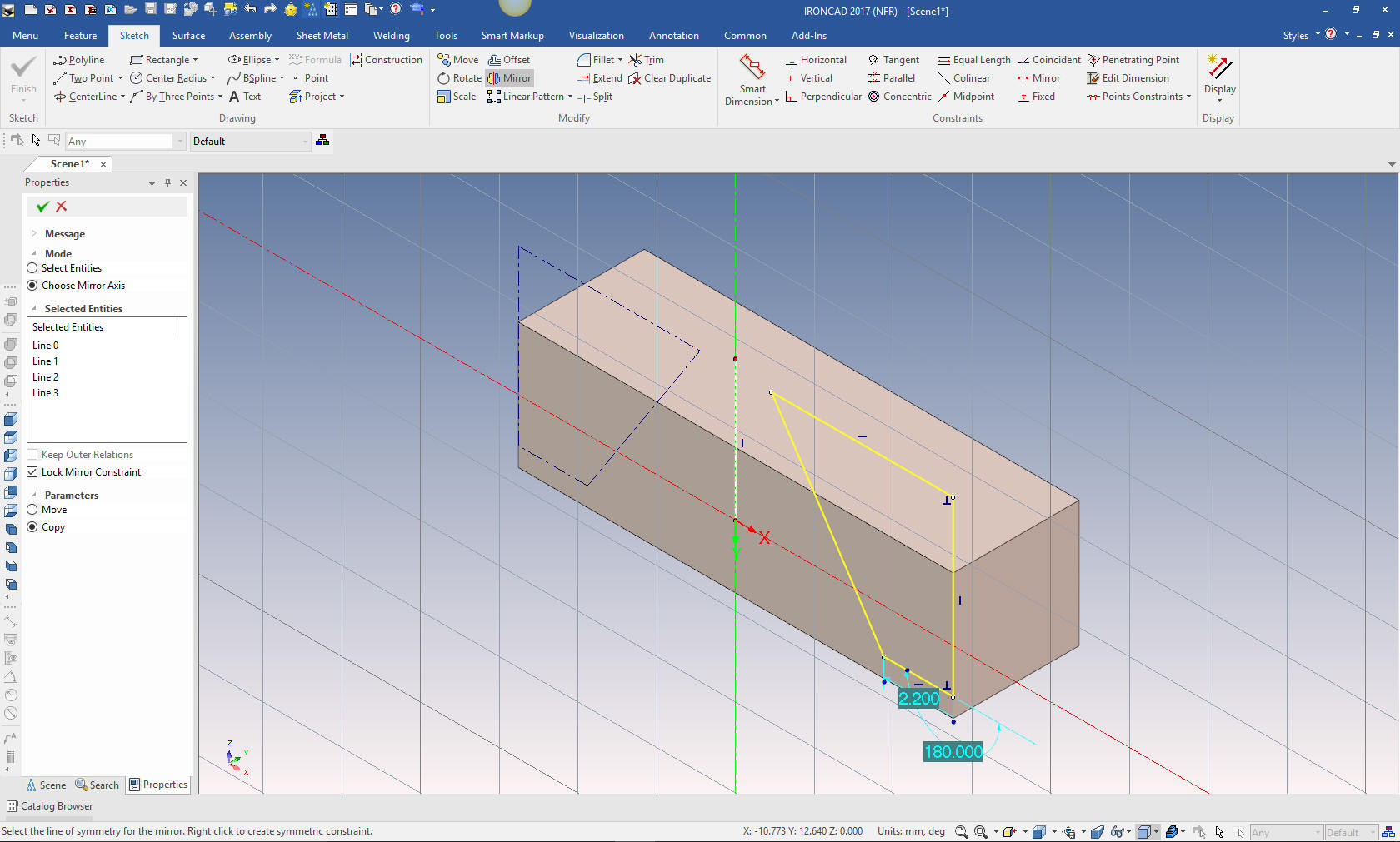
I create a vertical line in the middle to create a mirroring axis.
Mirror the profile, delete the vertical construction line and we are
ready to extrude, which is just hitting okay
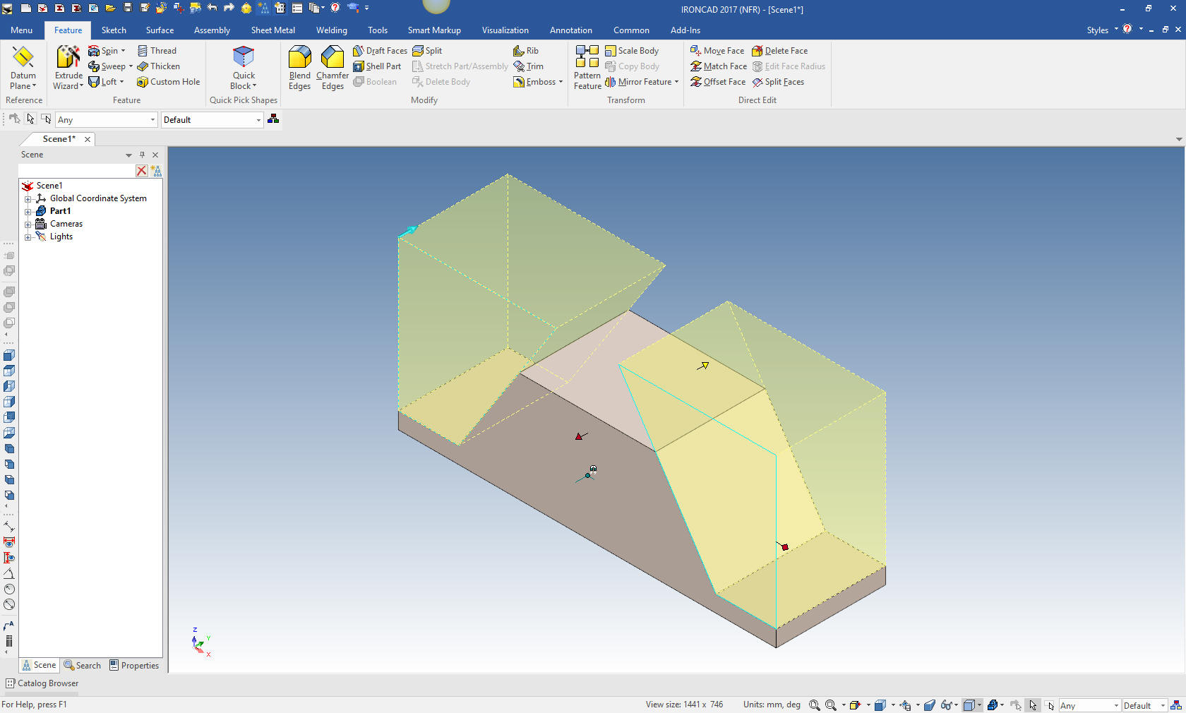
We pull the handle to size the extrusion.
We now create the center cut by dragging and dropping a hole block
on to the center of the top face and size it. You can see this is an
incredibly different way to design. The Fusion 360 could have easily
done this. But it takes a different way of thinking. This is not to
criticize the presenter but to realize how he was trained. I could
have easily created a sketch to do this. But a sketch is two step
process and a drag and drop is one.
Do you see this level of simplicity in your modeling?
This is time saving for simple parts imagine a complex part.
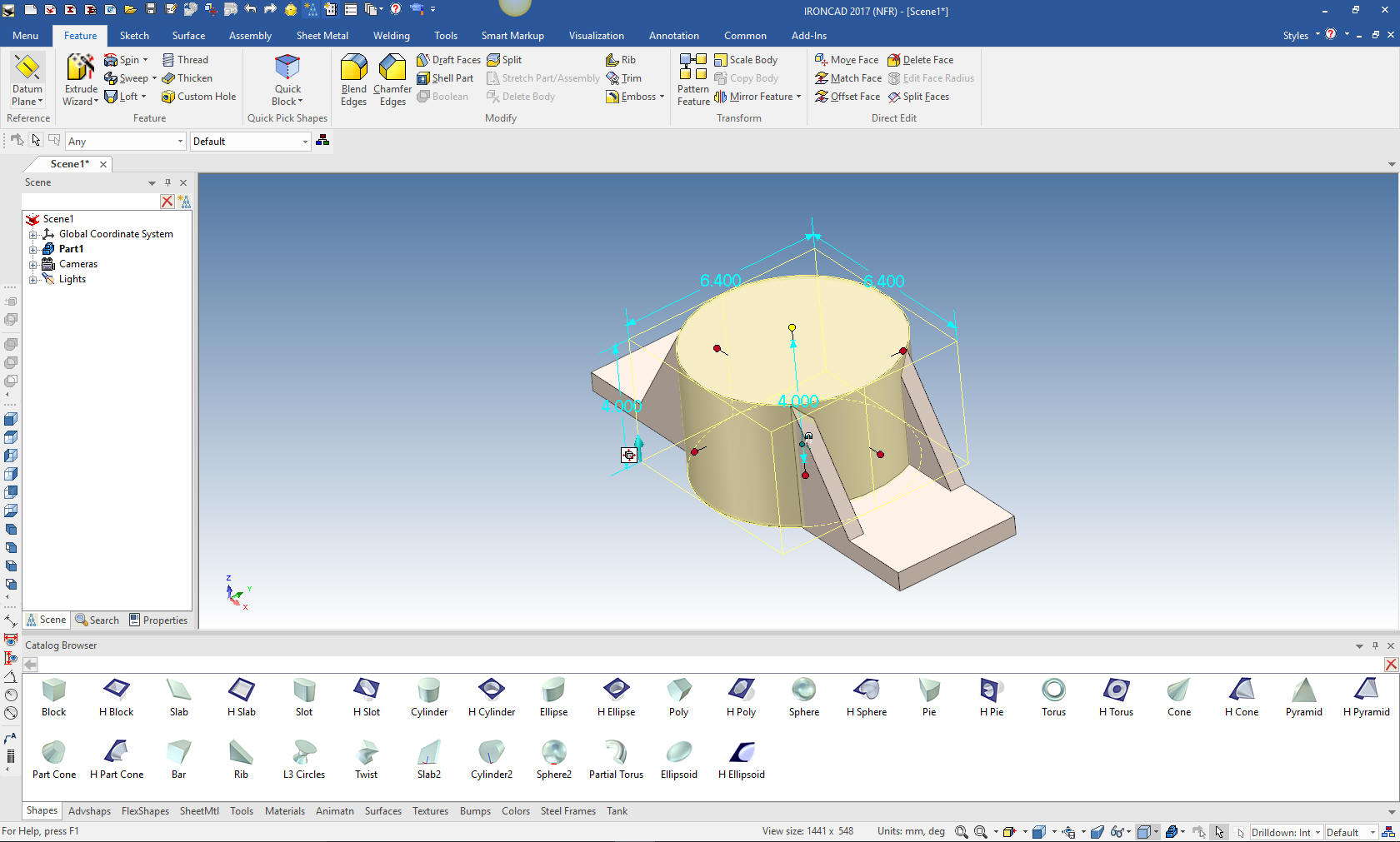
Now we just drag and drop a cylinder to the center of the rectangle
and size it.
We will do this cut two ways.
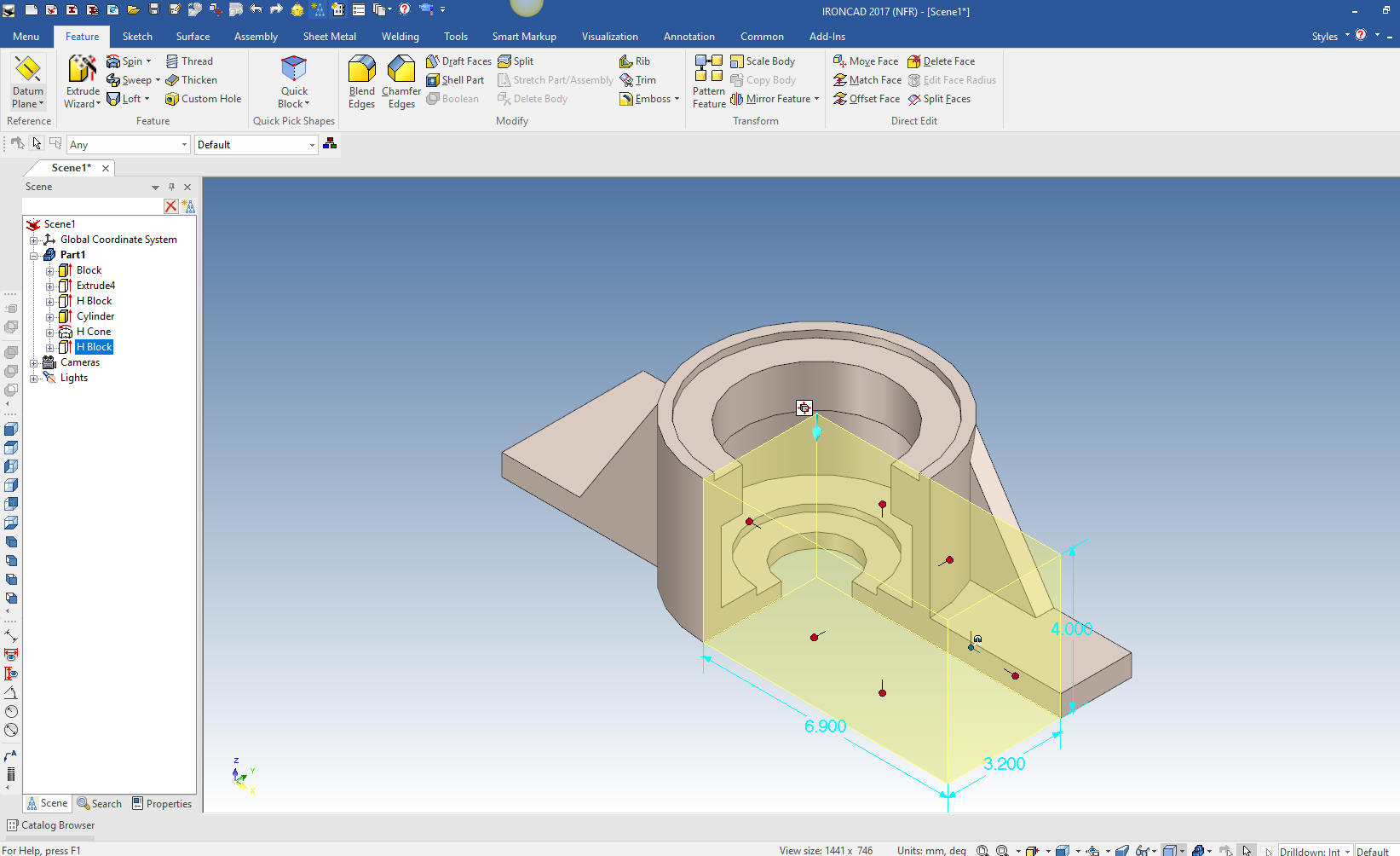
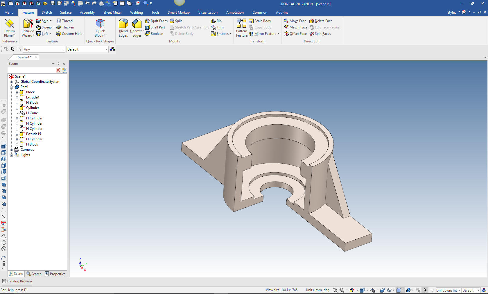
Sketching: Here is the center cut process done with a revolve cut based on
a sketch. A few years ago I started just dropping a positive or
negative cone to location I need a revolve. I think it is very
clever and highly productive. We will drag and drop the negative
cone to the top of the cylinder.
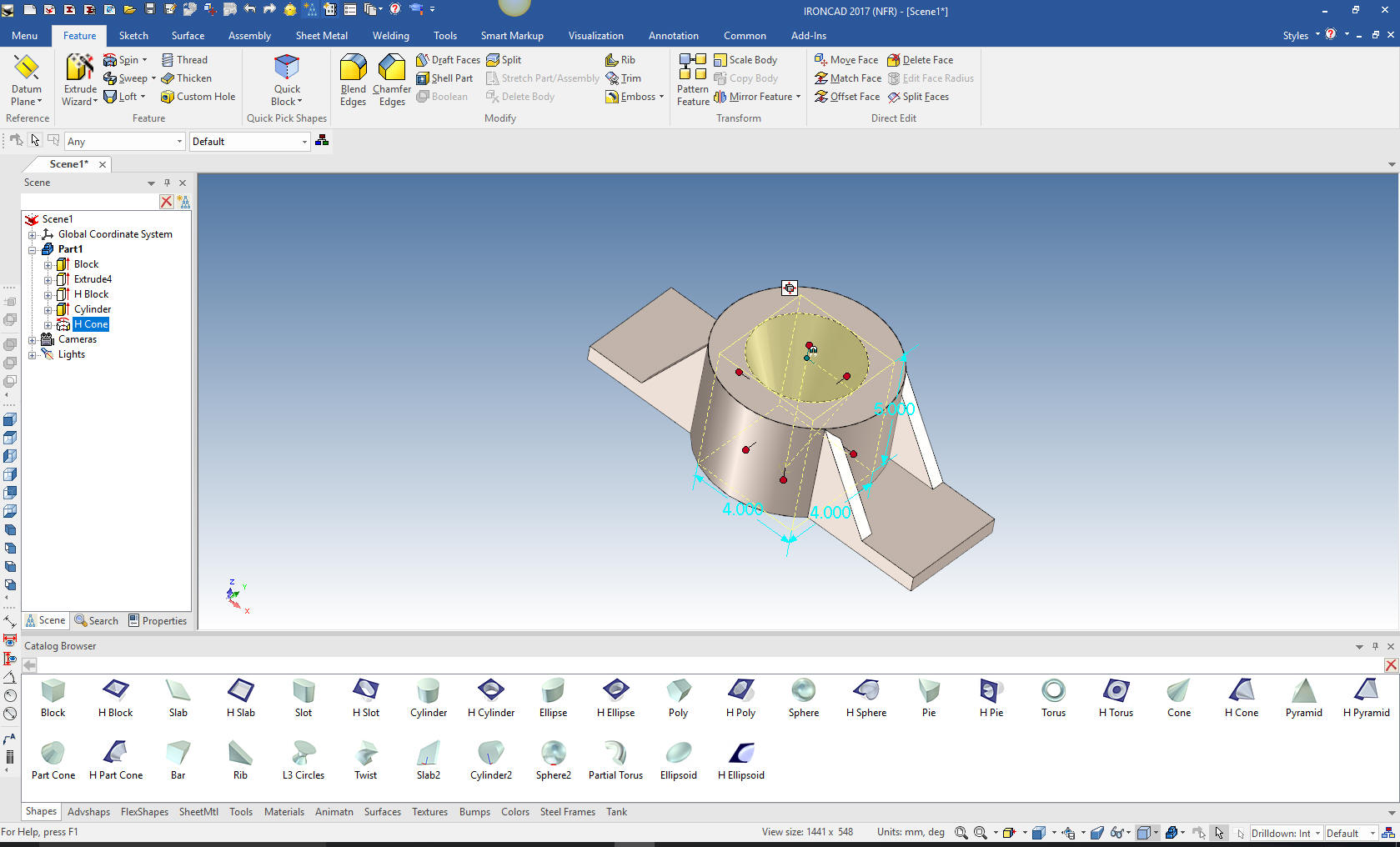
We select the cone at the feature level and select edit cross
section and define the profile with a mixture of projected edges,
offsets and defined lines.
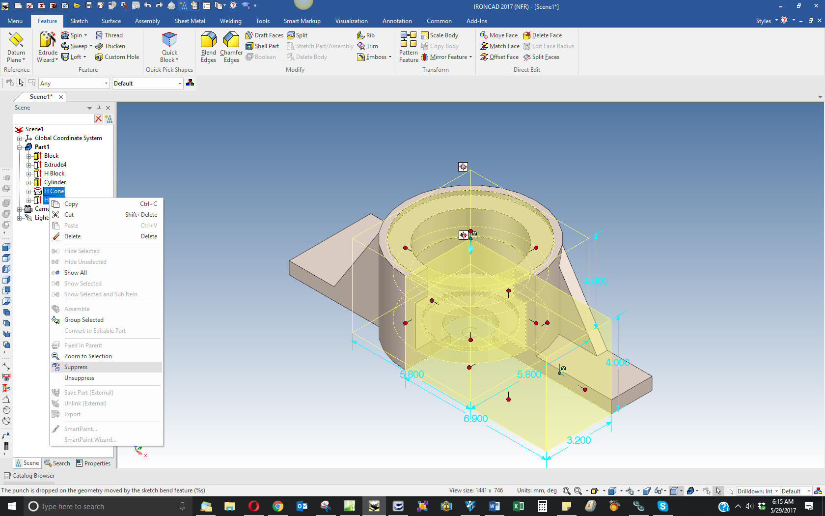
We now have the center section removed. We drag and drop a hole
block to show the result of the revolve. We can then delete the hole
block or we can suppress it in the history for use later when we may
want to evaluate the part.
Drag and Drop:
We just suppress the revolve and hole block (we will bring it
back later).
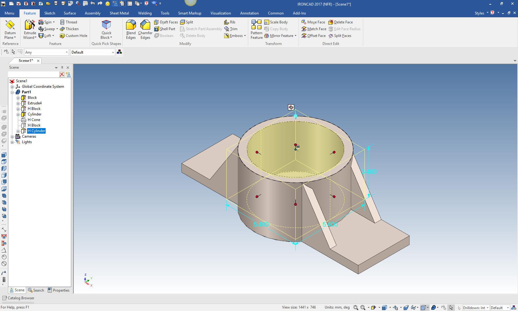
We those features suppressed we start and start by dragging and
dropping and sizing the largest hole cylinder.
Then next cylinder will be the thin bottom cut. Why? Because we want
a face to reference the center for the small hole in the bottom. We drag and drop it
at the center and size.
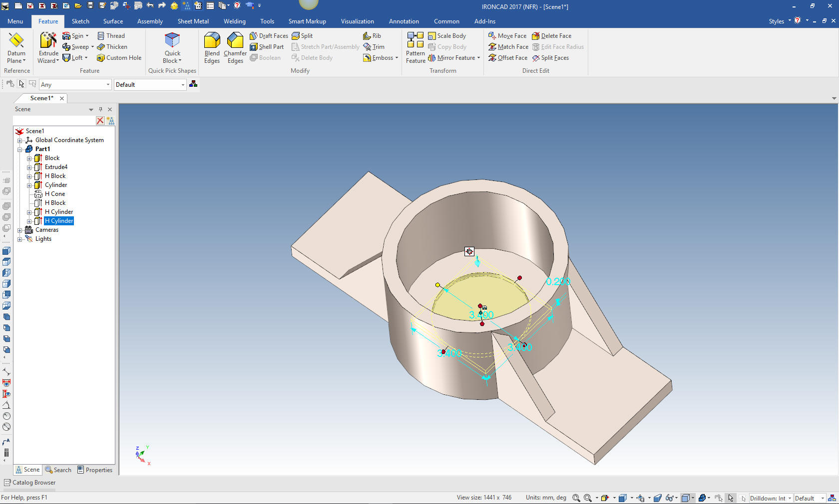
Now the bottom hole. Again drag and drop the hole cylinder to the
center and size
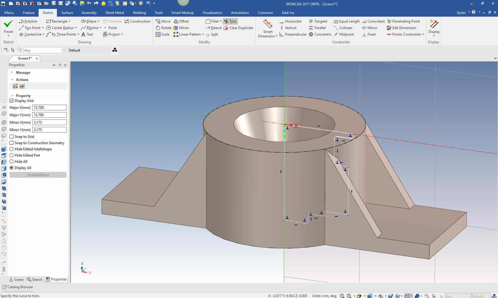
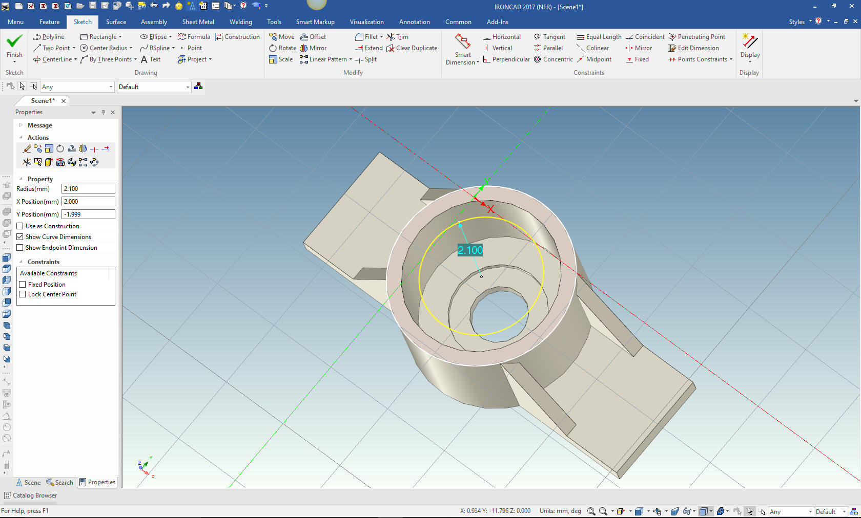
Now for the top. I will not drag and drop a cylinder I will use the
extrude wizard to create the top cut. I can do that with one step
by just projecting the outer edge and creating the center circle. I
have already set the depth in the setup of the extruson.
We select okay
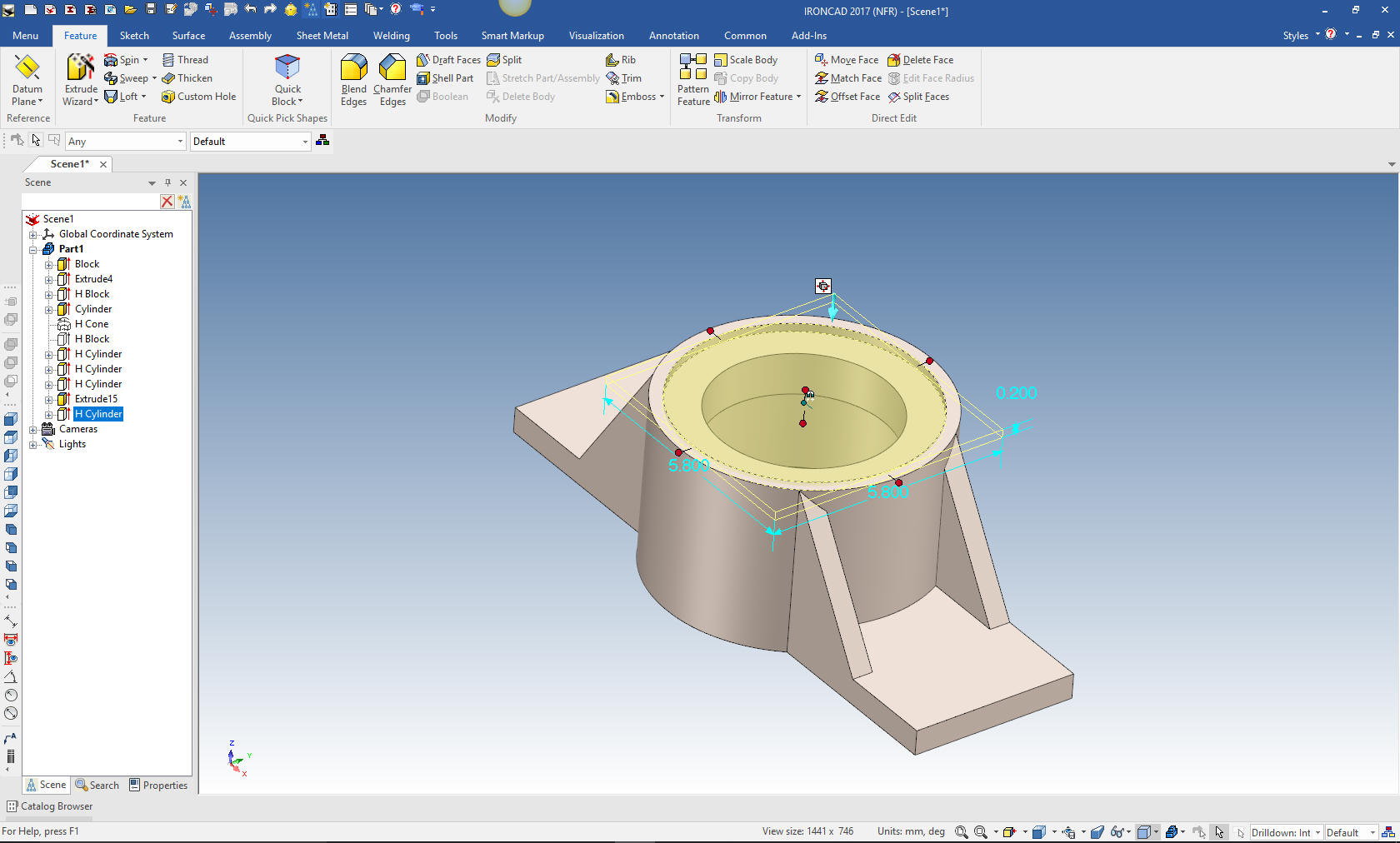
We again drag and drop a hole cylinder on the top and size it.
We go back to the scene browser and
move the hole block to the bottom of the history, unsuppress and we
see the cut is complete.
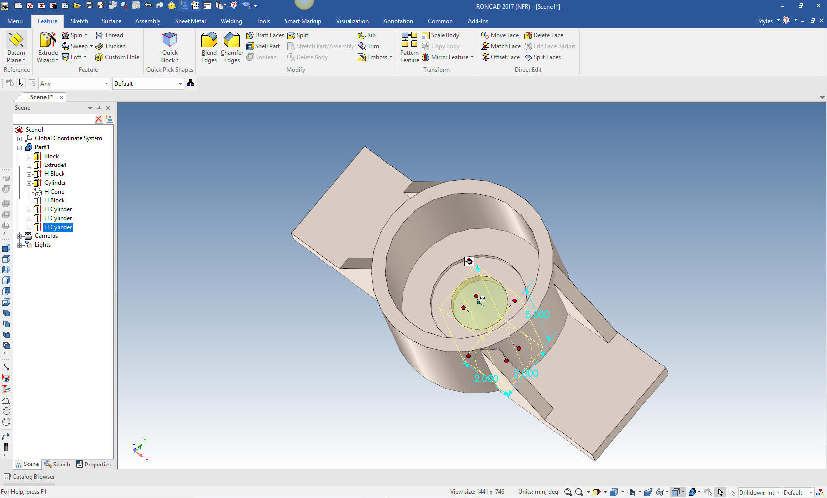
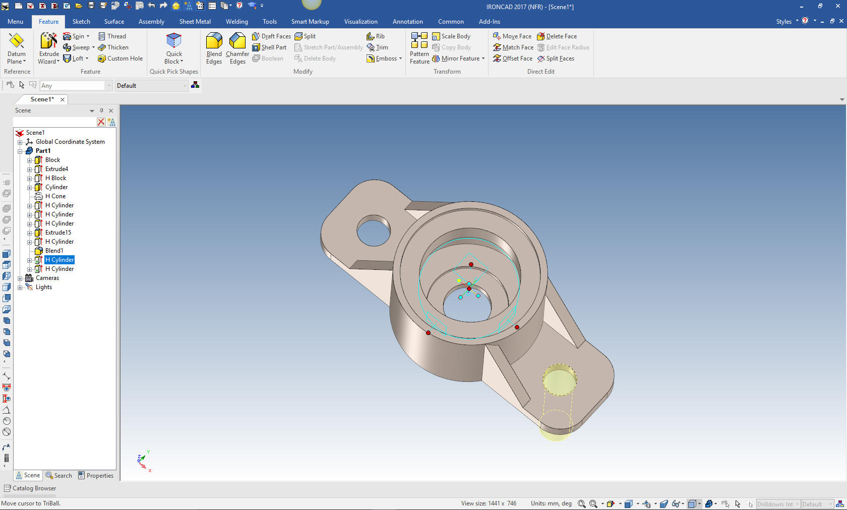
Now for the blends and holes. We
create the blends and drag and drop the hole and located it with the
triball. We select the hole, activate the triball, hit the spacebar
that allows placement of the triball, we move it to the center of
the cylinder, hit the spacebar again to reactivate the triball and
mirror link the hole and we are done.
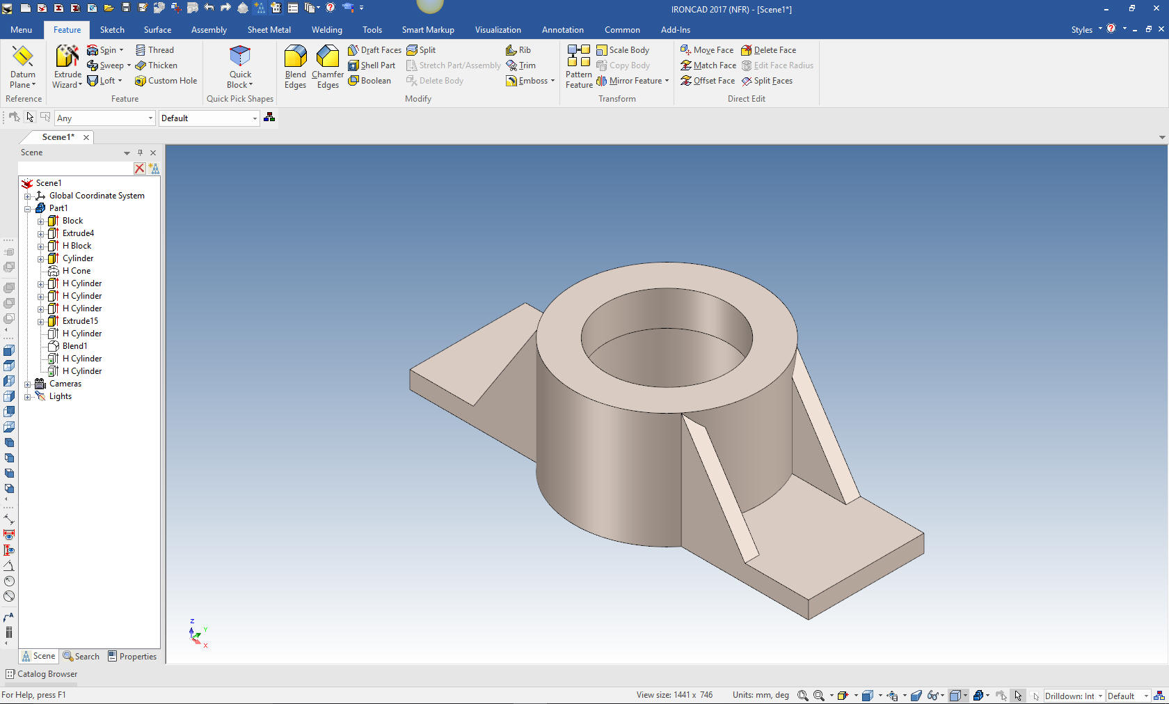
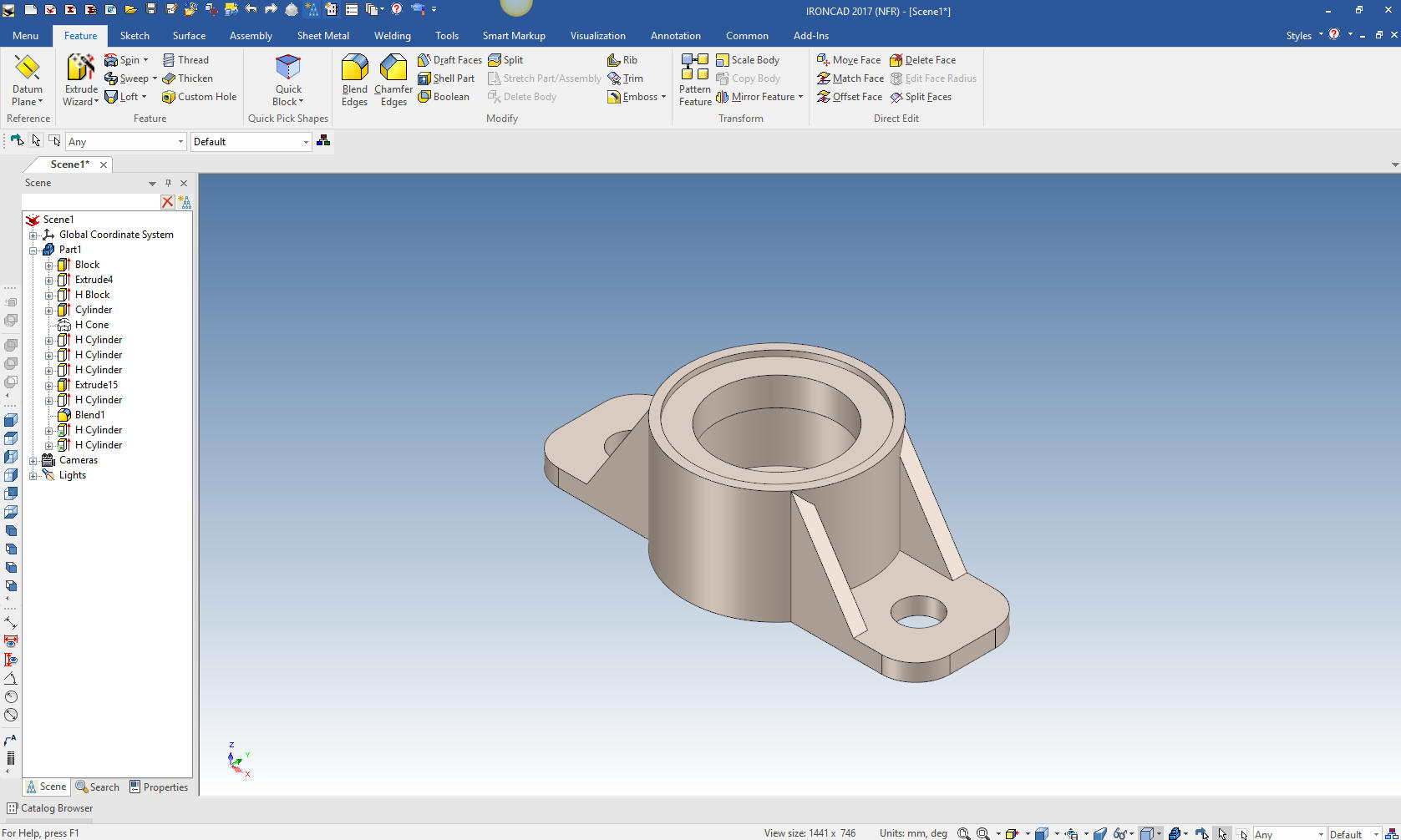
Here you go. Showing you a different more
streamlined way of modeling. You can see how this way of modeling
offers much more flexible options. The sketch, sketch, constrain,
constrain world of Pro/e that was developed almost 30 years ago is
very, very time consuming.
It is
very important that you look into how you or your engineers are
creating the parts. Streamline Sketching and Feature Based Modeling
is easy to learn and implement. It, alone, will increase
productivity 10X. Now, IronCAD with its unique integrated
history/direct edit functionality can increase your productivity
another 5X or more with changes! Again, time is money in
engineering.
More on Streamline Sketching and Feature
Based Modeling.
To experience this increased level of productivity, please download
IronCAD for a 30 day evaluation. Legacy data is no problem, IronCAD
can read the native files of all of the popular programs. IronCAD is
a great replacement for the subscription only Autodesk and PTC
products.
Give me a call if you have any
questions. I can set up a skype or gotomeeting to show this part
or answer any of your questions on the operation of IronCAD. It
truly is the very best conceptual 3D CAD system.