3D Modeling Techniques IRONCAD vs Solidworks
Lesson Nineteen Drag and Drop Design Streamlined Sketching/Feature Based Modeling
Just a Bit of Parametrics!
When I introduce IronCAD's very
flexible design paradigm I have a hard time to get the Pro/e clone
users, like Solidworks and other programs, to understand the drag and
drop design paradigm.
Download IronCAD/Inovate and
take the one day and 17 lesson course. I get rave reviews from my
new customers. Give it a try, this is a fully functional 30 day
evaluation with all of the native translators so you have access to
your legacy engineering information.
I saw some Fusion 360 exercises online and I decided to compare
IronCAD. It quickly turned into a study in modeling techniques. I have created
many comparisons to Fusion 360, Onshape, Solid Edge, NX, Creo,
Catia and Inventor
lessons to show the difference between
IronCAD and my modeling techniques. I found the presenters working
identically wasting massive amounts of time
with overly complex constrained sketching procedures. I was so unimpressed that
I decided to model the parts or assemblies showing my modeling techniques plus IronCAD's superb design system.
3D Modeling Techniques Defined
Many of these modeling techniques can easily be implemented even
within their existing system. I call it Streamlined Sketching and
Feature Based Modeling. Please review a few of the above IronCAD
comparison lessons, there are some very stark differences.
While creating 3D models from drawings is the very best
way to learn 3D CAD and maybe some design techniques it does not
expose the designer to the design flexibility necessary in design. IronCAD is all top down due to the single model environment.
Creating mating parts is a cruise. But modeling is just one aspect of a
well designed productive 3D CAD system.
IronCAD vs Solidworks
I would do a
video, but I really am not good at it. So I will show you step by
step. I will try and get IronCAD support to create one. They are
very good.
As with my Ironcad vs
Fusion 360 and other major CAD systems, I have found the same problems with Solidworks. The modeling
technique is hugely responsible for the level of productivity. Those
of you that are only trained in the constrained sketching world are truly limited by not using the freedom of
Streamlined Sketching and Feature Based Modeling, that is available in even the most Solidworks-ish of CAD systems. If your
designers are designing in these very unproductive and time
consuming processes it might be time to review your standard design
processes. Don't have any do you?
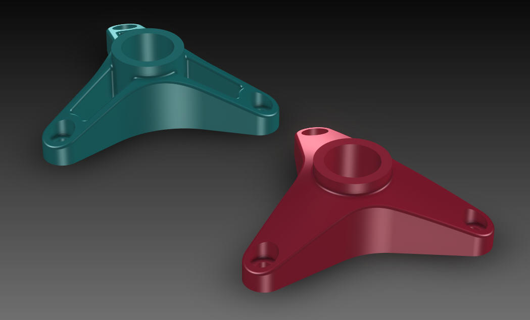
This IronCAD exercise took a few minutes and allows
for faster and much easier modification. Again these exercises turned
into a study of modeling techniques even though most of this model
is Feature Based Modeling not available to most of the Solidworks clones.
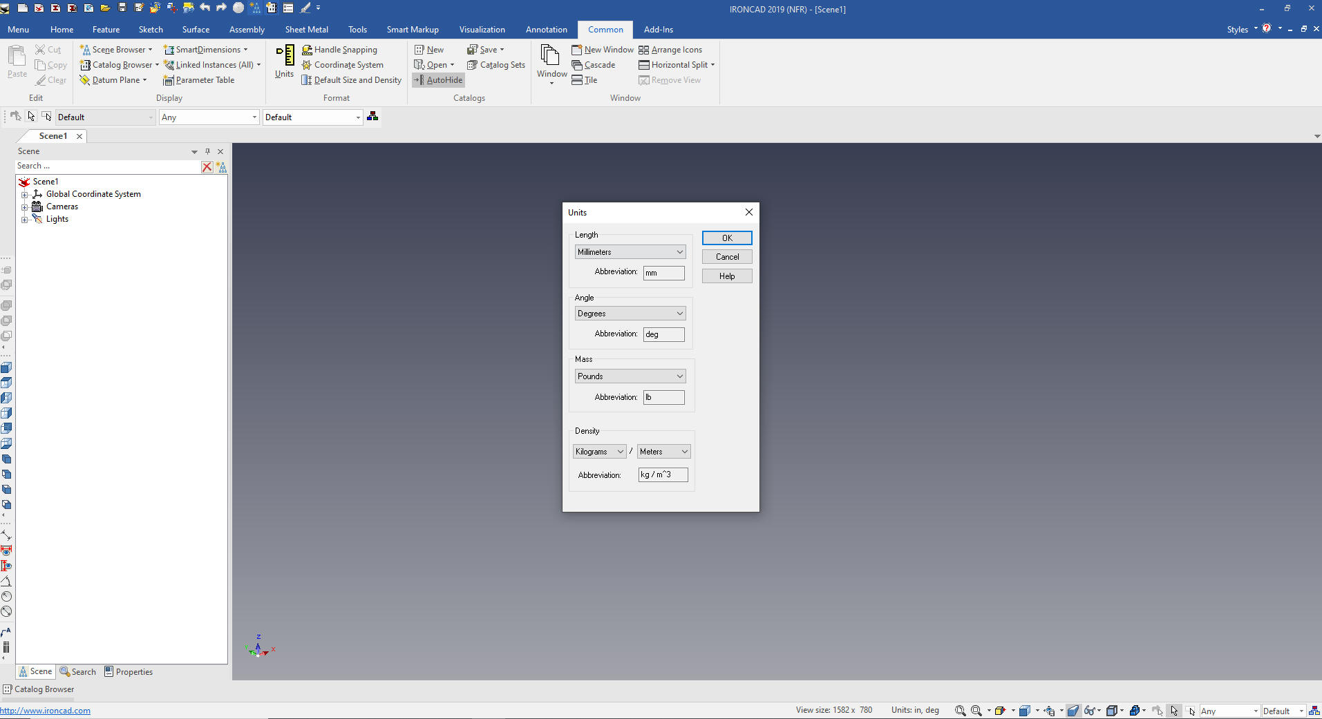
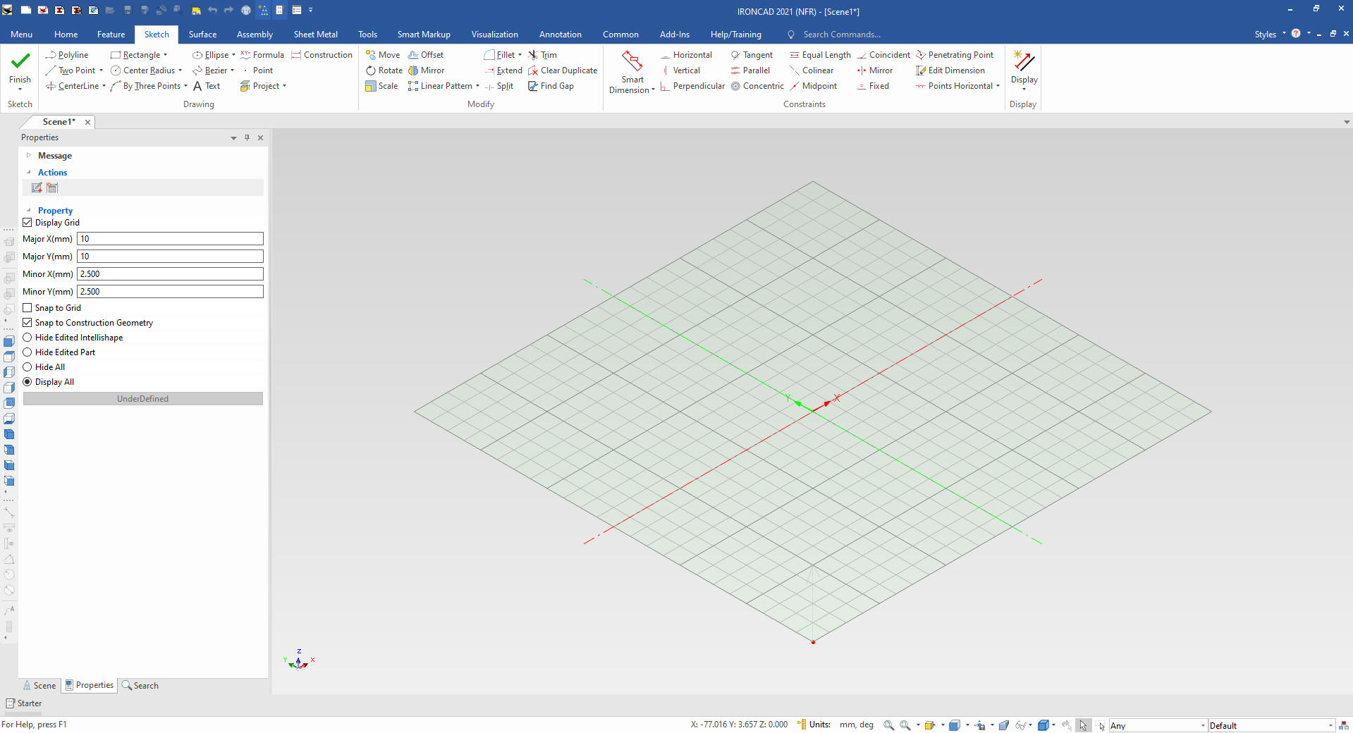
Here is IronCAD. My default is inches,
so we will set the units to mm. Let's get started.
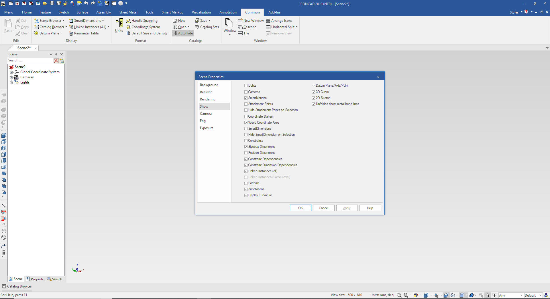
I put the cursor in the scene and right
click and select show and pick show the size box dimensions it makes
it much easier to work with setting the dimensions. You can save your custom
configurations if you want.
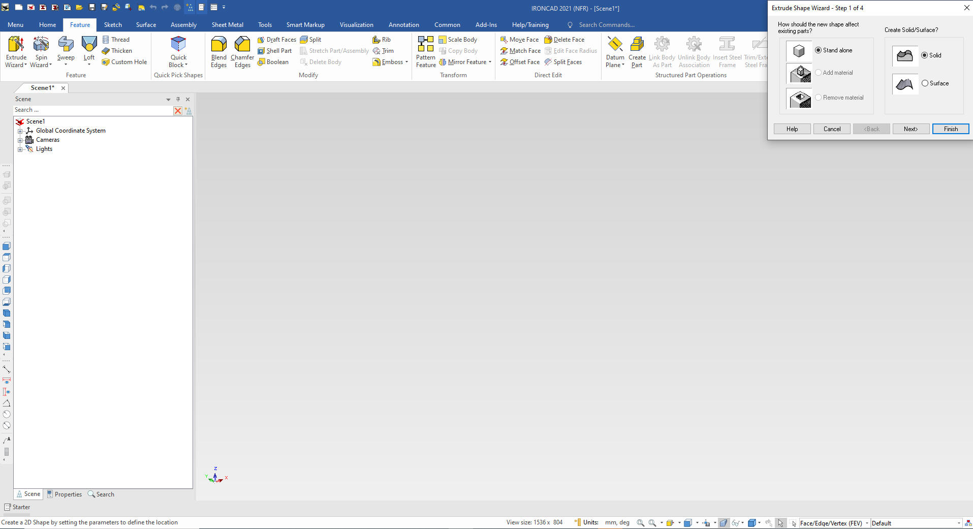
The
first thing we do is use the extrude wizard to create a sketch
plane! We select standalone part and can set the extrude distance.
Note: Why does IronCAD
call it a scene instead of a workspace? IronCAD was first released
as a graphic design program called Trispectives. It still has much
of the graphic design functionality. It truly is a wonderful mixture
of professional 3D CAD and graphic design, which puts it in a much
more flexible category as compared to the very mechanical
engineering focused Solidworks clones.
The sketch automatically it set to X0Y0Z0. We set the
view to ISO.
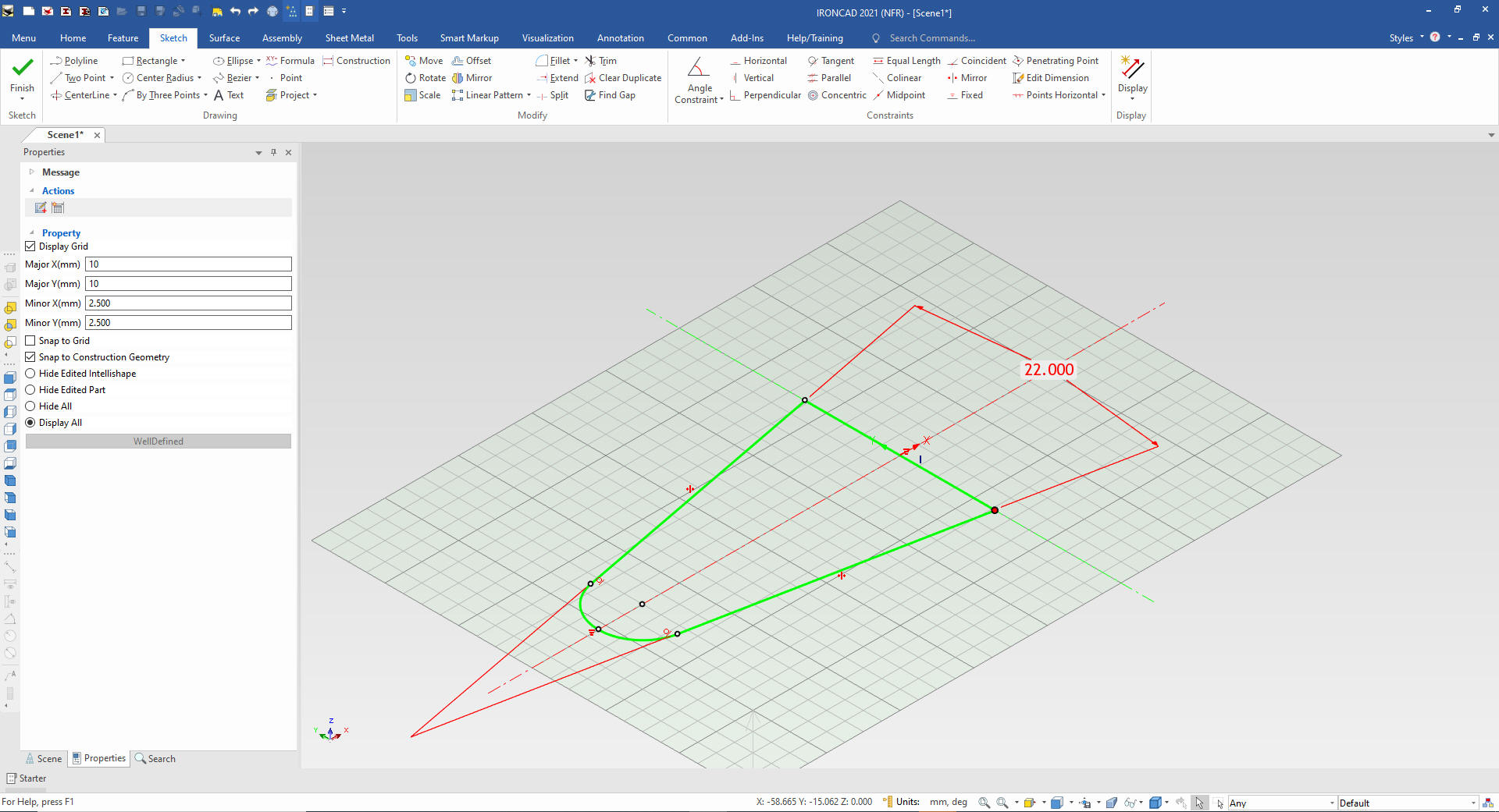
We create the sketch with the
constraints and the parameter operator. We don't need dimensions
since IronCAD can define them at creation, eliminating one step.
This is a
parametric design with constrained entities. I have never done any
constraining or parametrics. My customers have a wide variety of
products that do not make it conducive. I usually use Streamlined
Sketching which I will show later.
Most design does not need
parametric options. Most would not have the foresight of how the
design might change. This is a nice little parametric exercise.
We select
finish and you can see we have our shape.
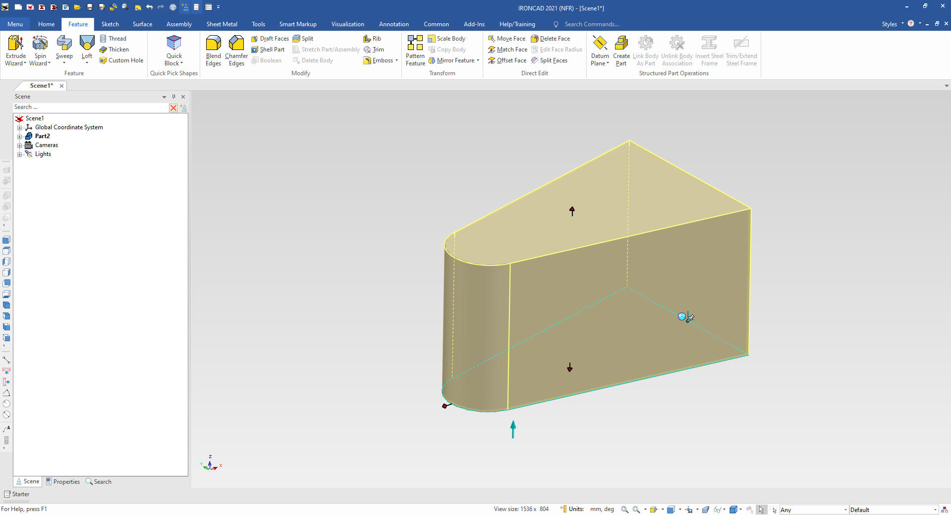
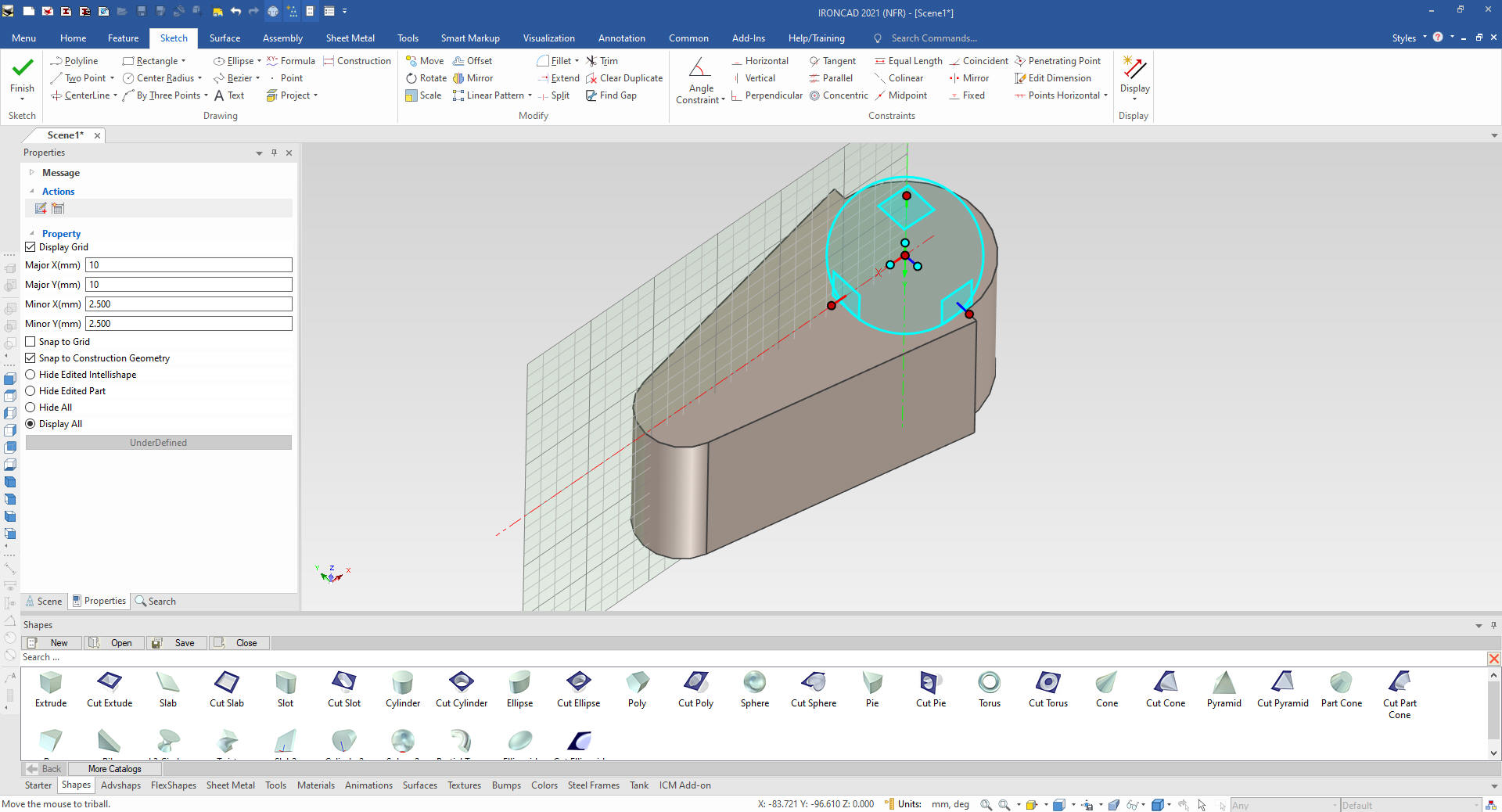
We
will now drag and drop a cylinder on the middle of the right upper
edge and size it by pulling or pushing the appropriate handle to align with the top and bottom. You do
that by holding the shift key down and the entities will light up in
green. You can also just select to point from a right click from a
dialog box!
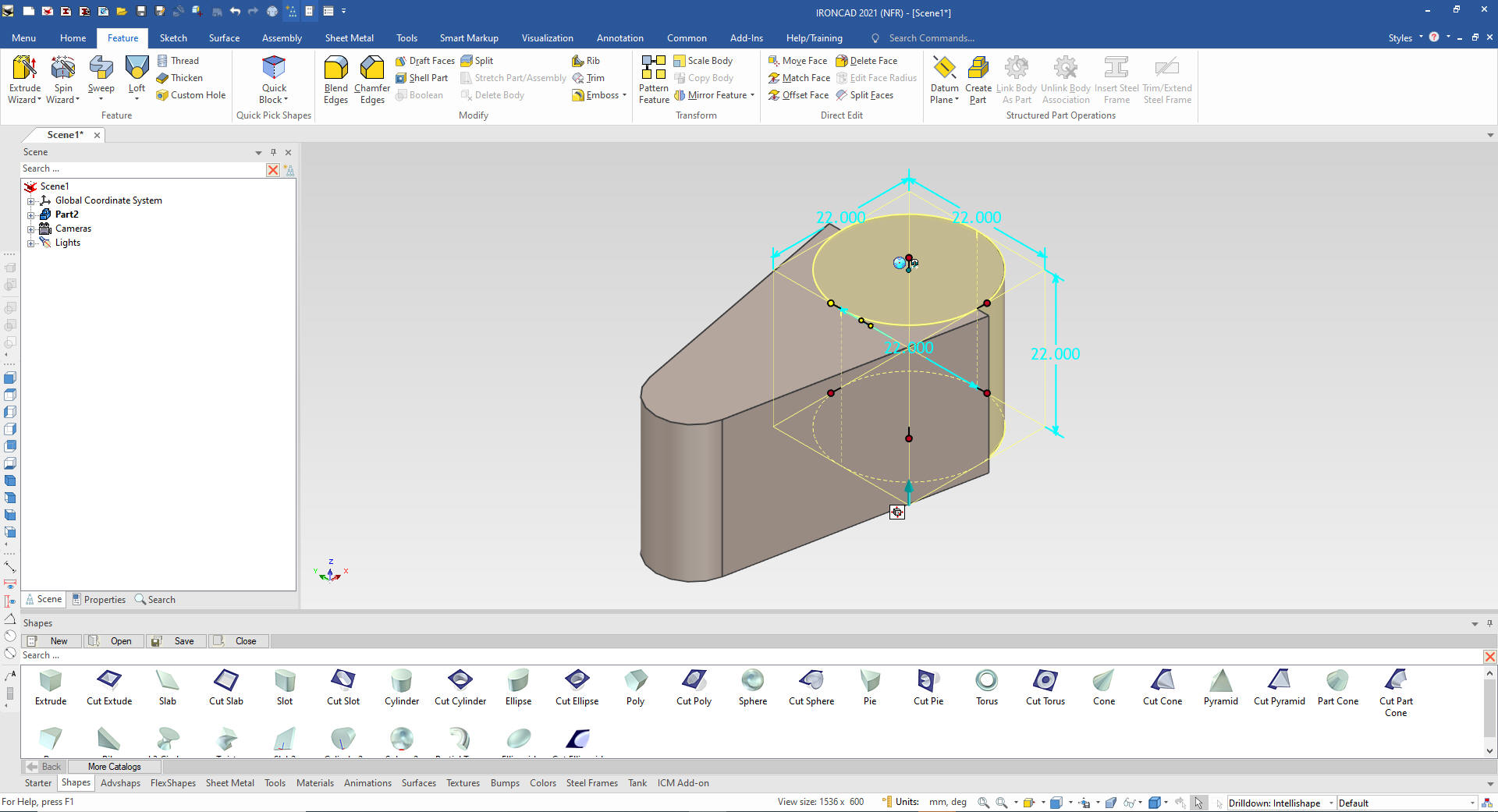
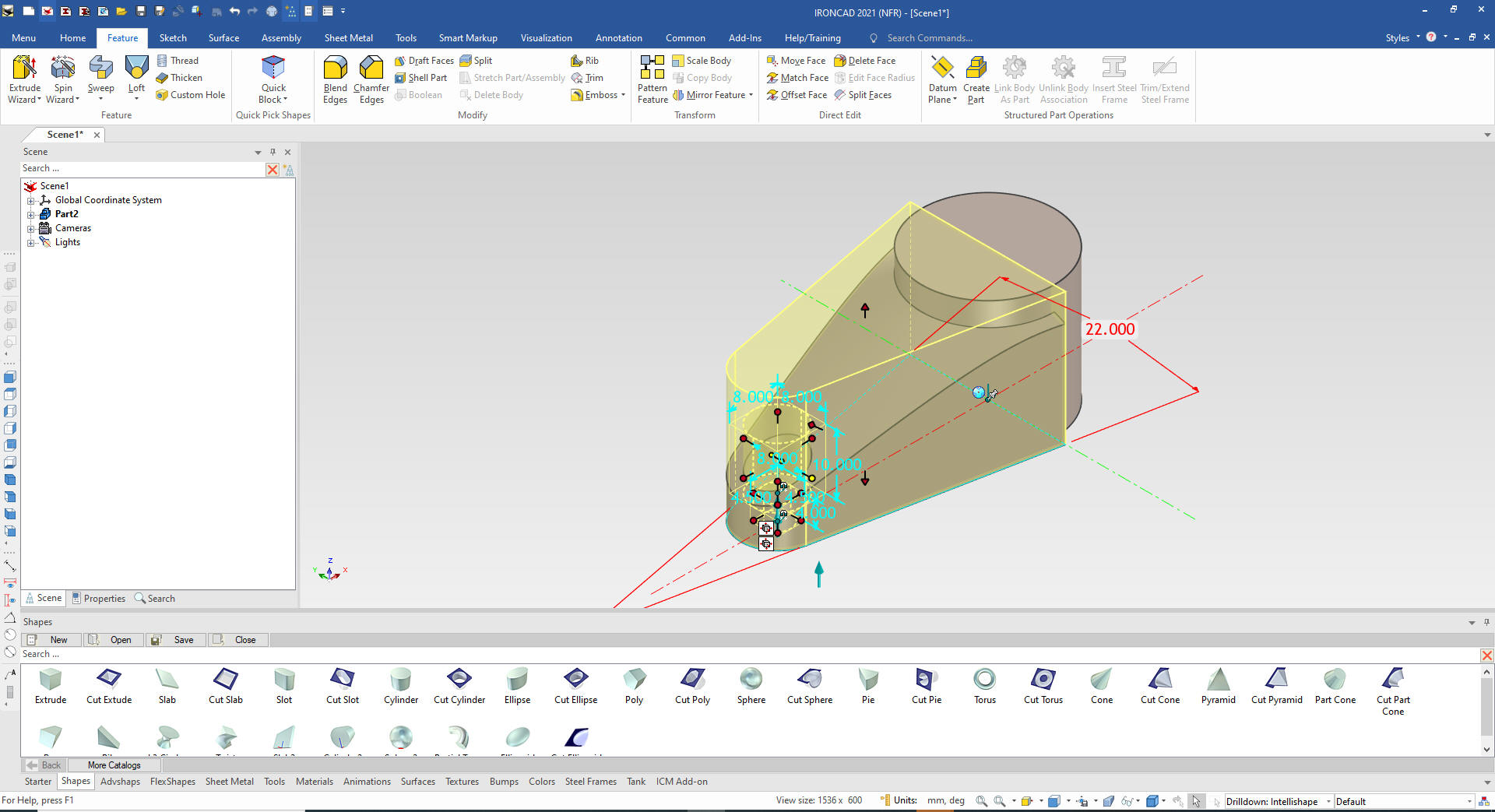
Using the spin wizard set it to
remove material and leave it at 360 degrees we set the sketch at the
center of the cylinder by selecting parallel to face at point and
orient the sketch with the Triball.
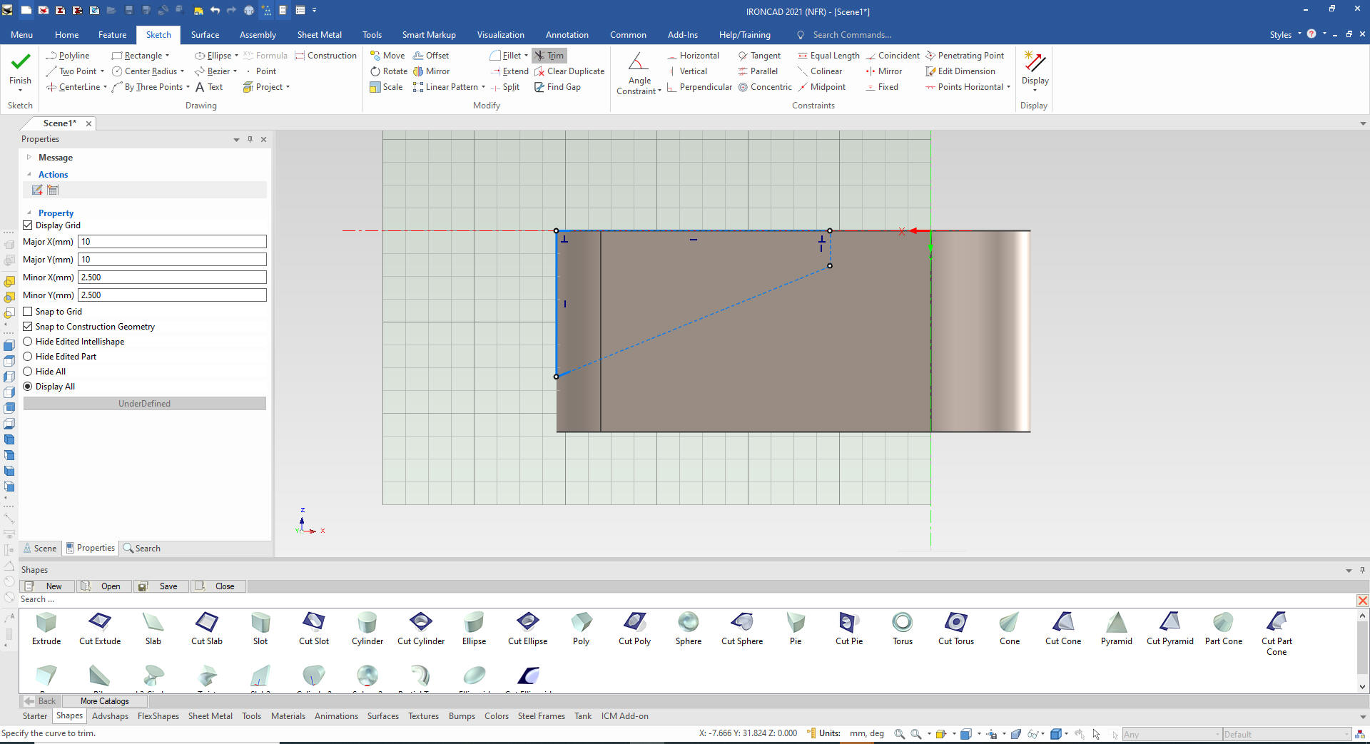
I
create the sketch with streamlined sketching projecting the
pertinent edges.
We select finish and it cuts our
shape.
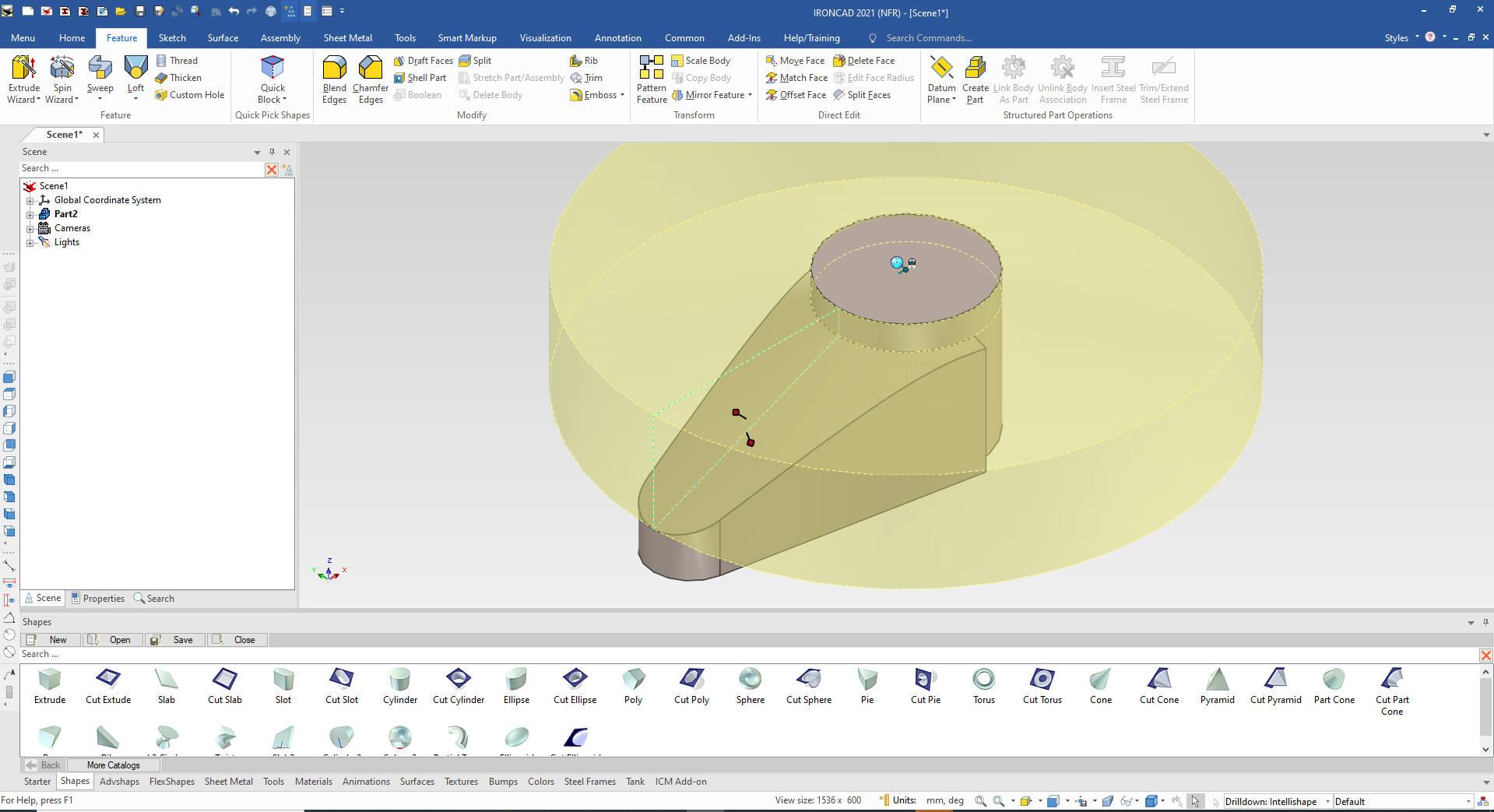
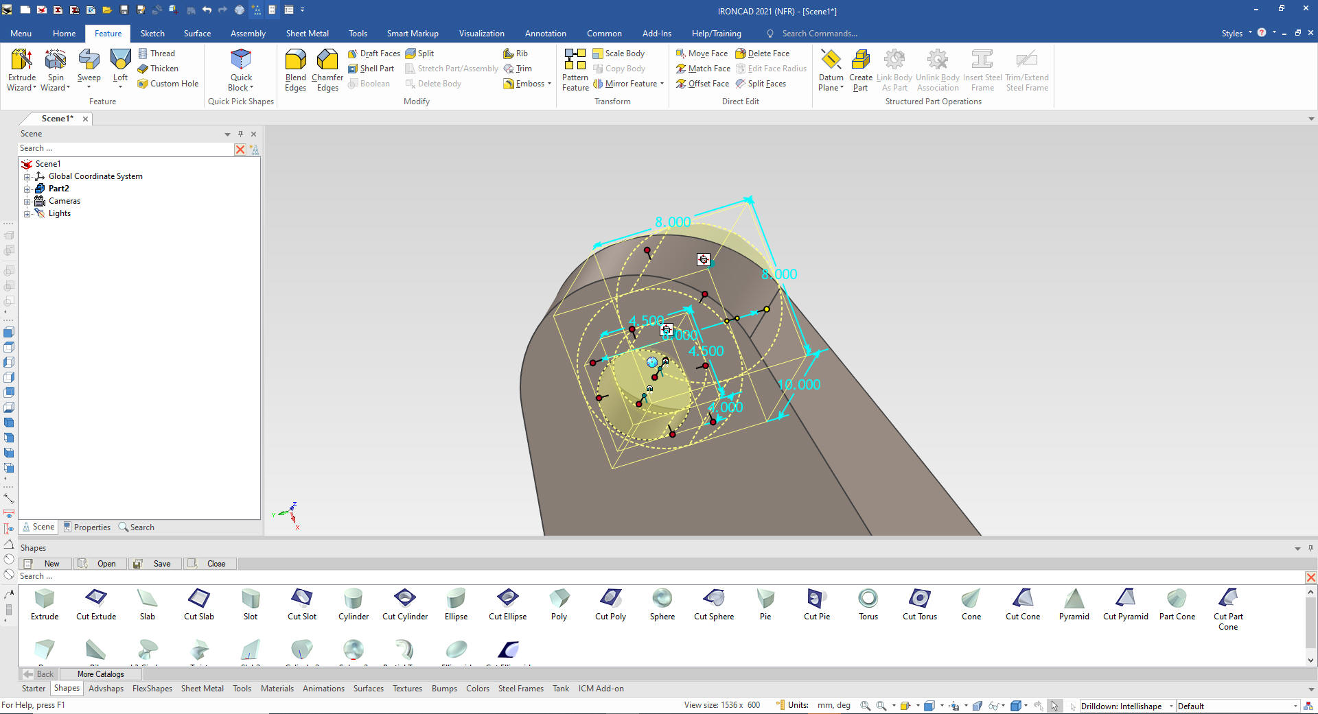
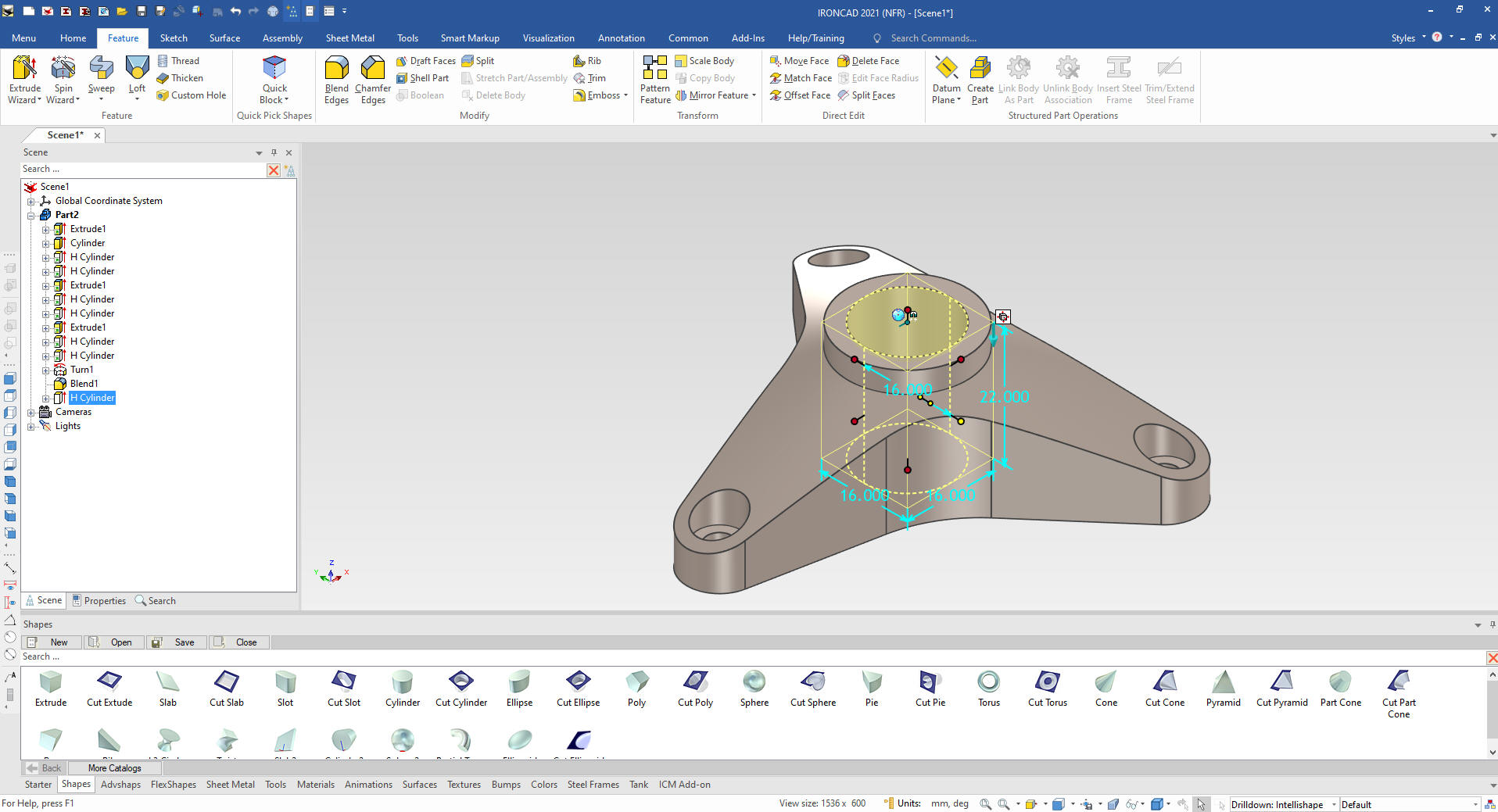
Now we create
the holes by dragging and dropping the first 4mm hole to the center
of the radius and then the larger 8 mm hole at the center of the
first holes face and size it.
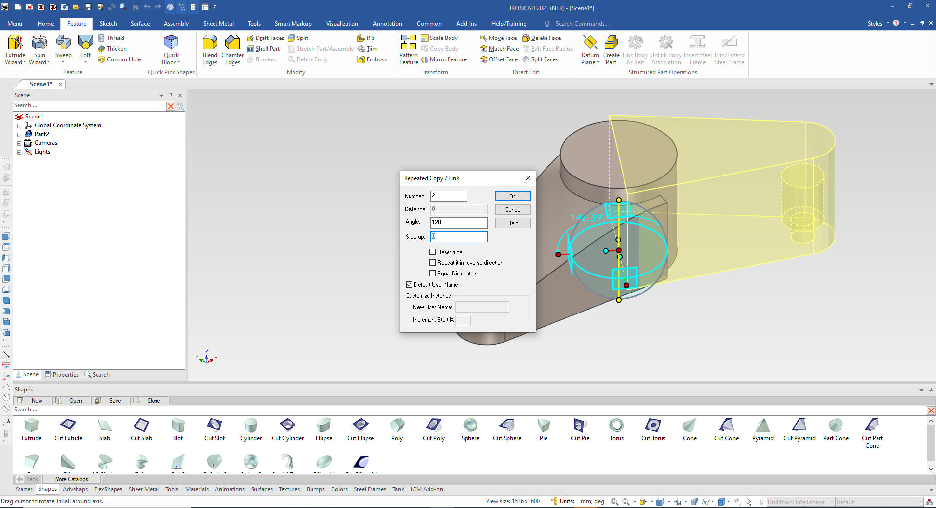
We select the shape and holes to
copy link the other two features. Linking allows when changing
one feature they all change.
With
the Triball we make two linked copies at 120 degrees. We could also
use pattern if the feature amount would change later.
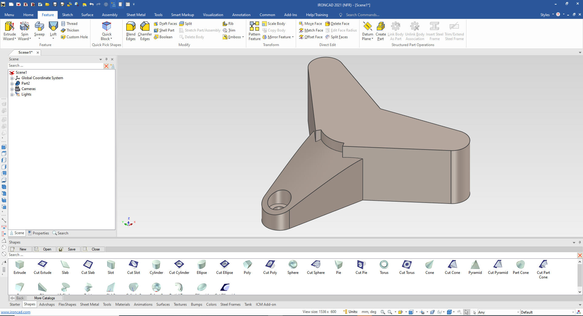
As
you can see the spin cut does not affect the new features.
We go into the
scene browser and move the "Turn 1" to the bottom of the features in
the history.
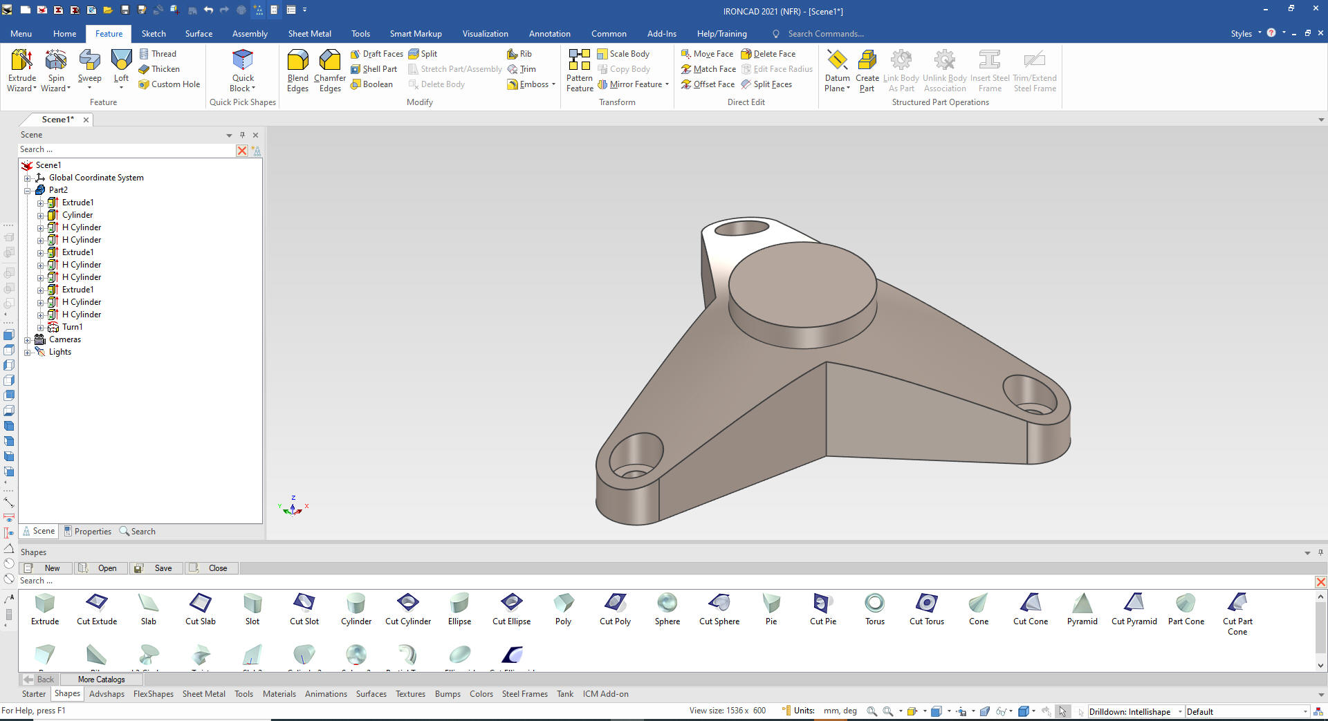
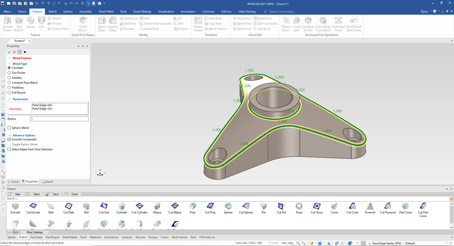
We add the large fillets and drag and
drop a cut cylinder to the center of the existing cylinder and size
it and we are almost done.
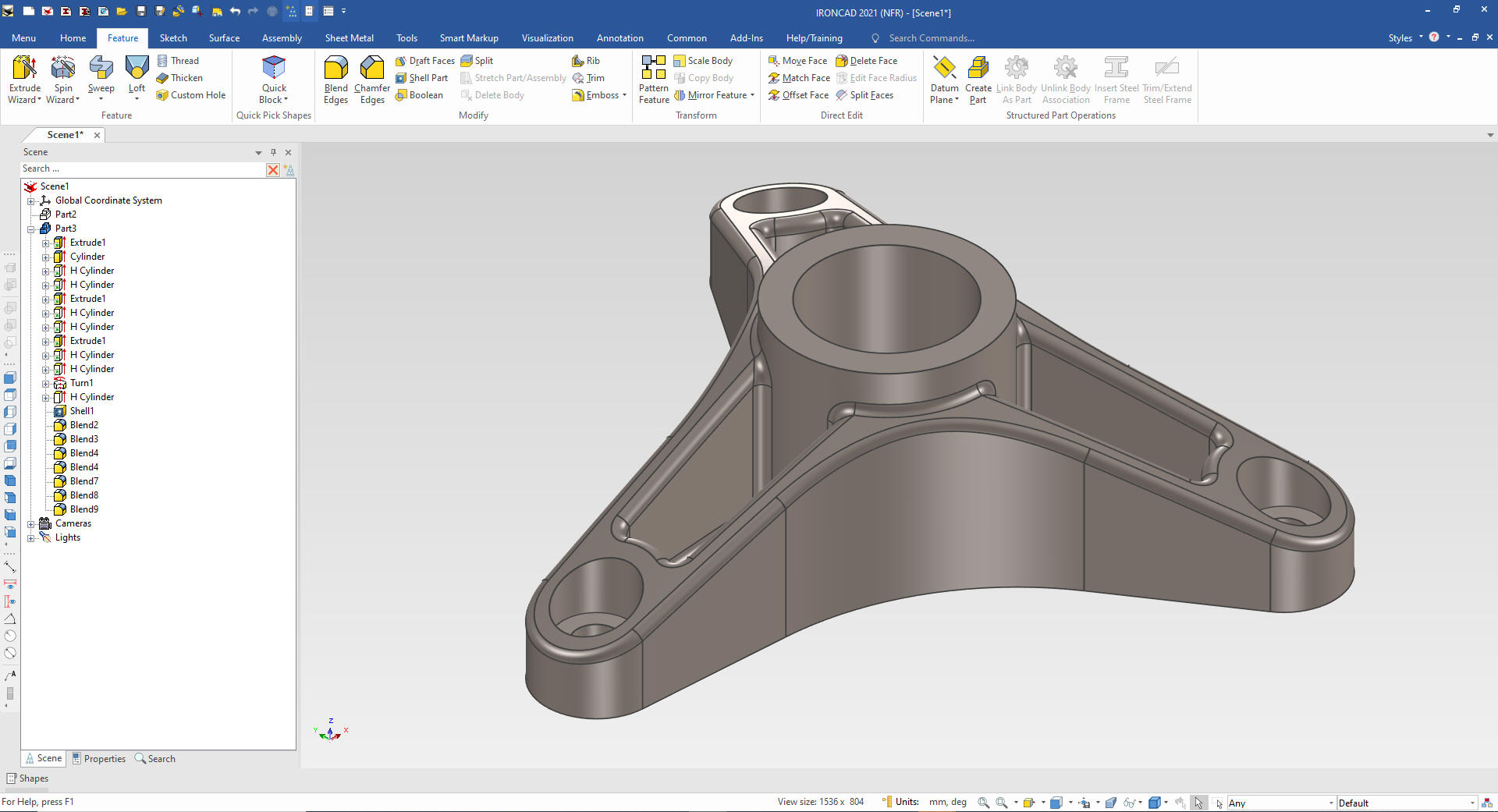
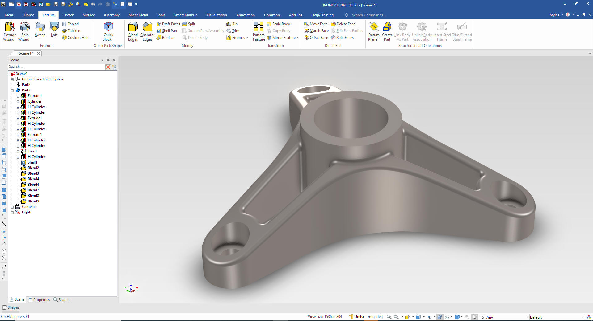
We
add the edge fillets and we are done.
We add a small bit of realistic rendering and we are finished with
the part.
Here
is the AID (Associated Information Document)
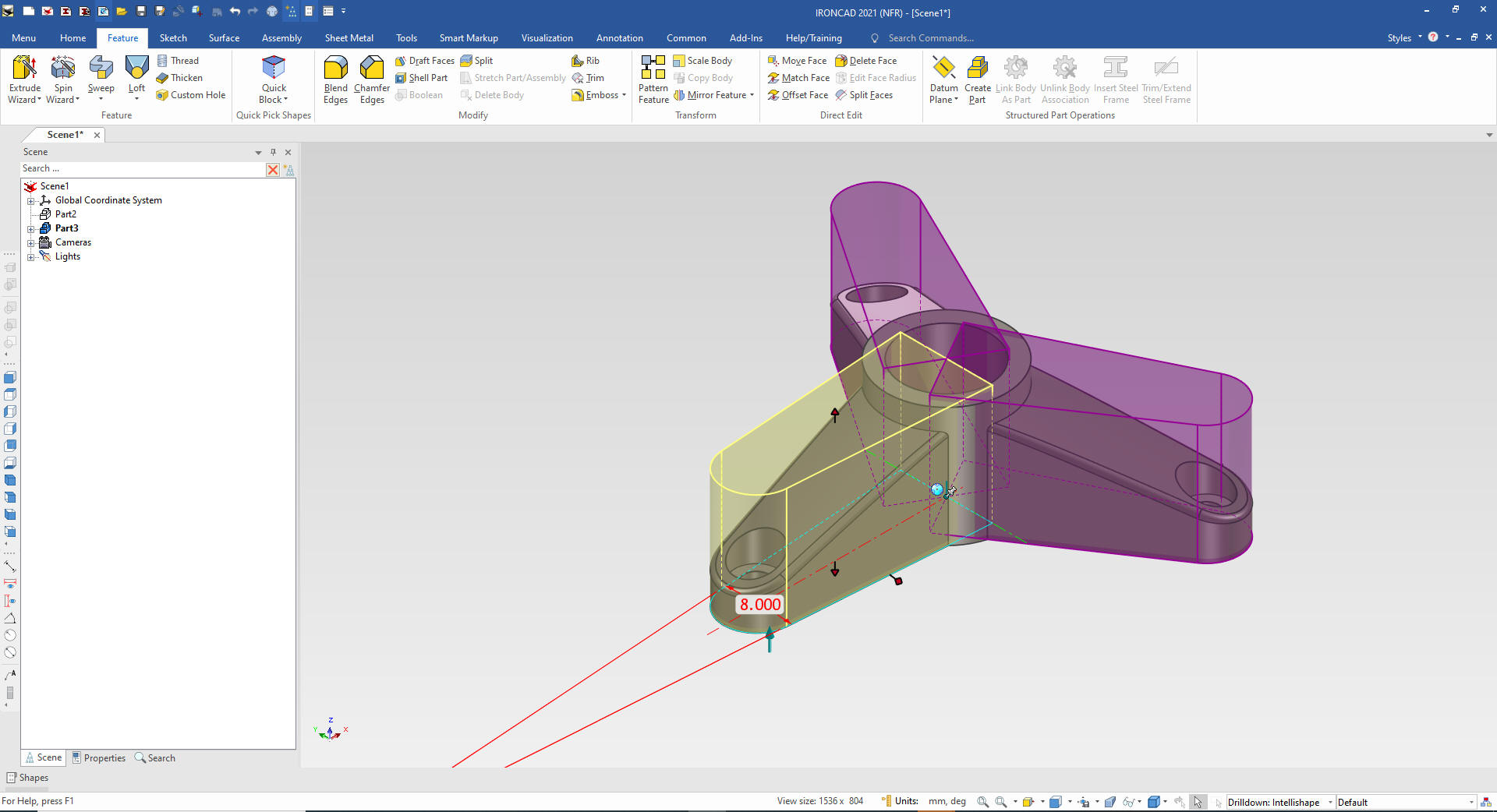
We now
have to make the changes. We will copy the existing model and paste
in the same scene. IronCAD is a single model environment where all
parts can coexist.
You can see in the scene browser there is
now a part 3.
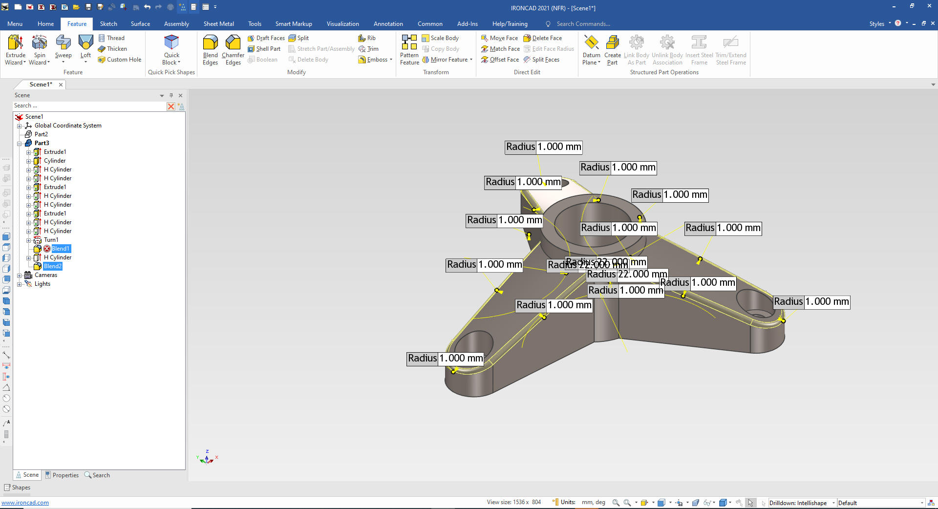
We change the 22 degrees to 8 degrees. You can
see all the shapes change. We will get errors due to the blends not
having the correct edges.
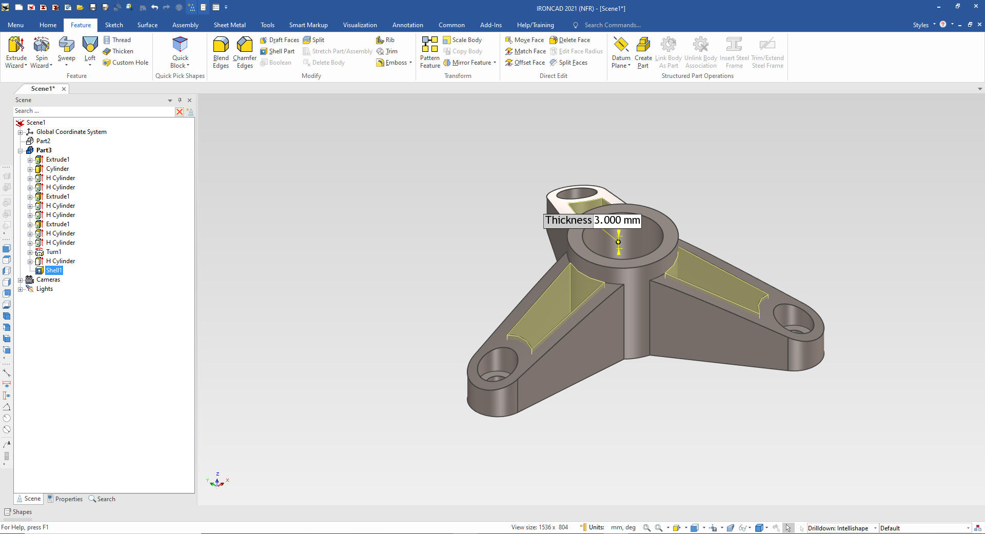
In
the scene browser we delete the corrupt blends and edge blends.
Now
we use the shelling command to create our pockets.
Give me a call if you have any
questions. I can set up a skype or go to meeting to show this part
or answer any of your questions on the operation of IronCAD. It
truly is the very best conceptual 3D CAD system.
If you are interested in adding professional
hybrid modeling capabilities or looking for a new solution to
increase your productivity, take some time to download a fully
functional 30 day evaluation and play with these packages. Feel free
to give me a call if you have any questions or would like an on-line
presentation.