3D Modeling Techniques
ZW3D vs Creo Lesson Six 3D Modeling Cannot Be This Convoluted Streamlined Sketching/Feature Based Modeling
Modeling note:
It is funny,
you may not realize how you model because you have many ingrained
processes from the past. I have been doing Boolean (direct edit)
design since the beginning of solid modeling in CAD. As I have been doing these comparisons I
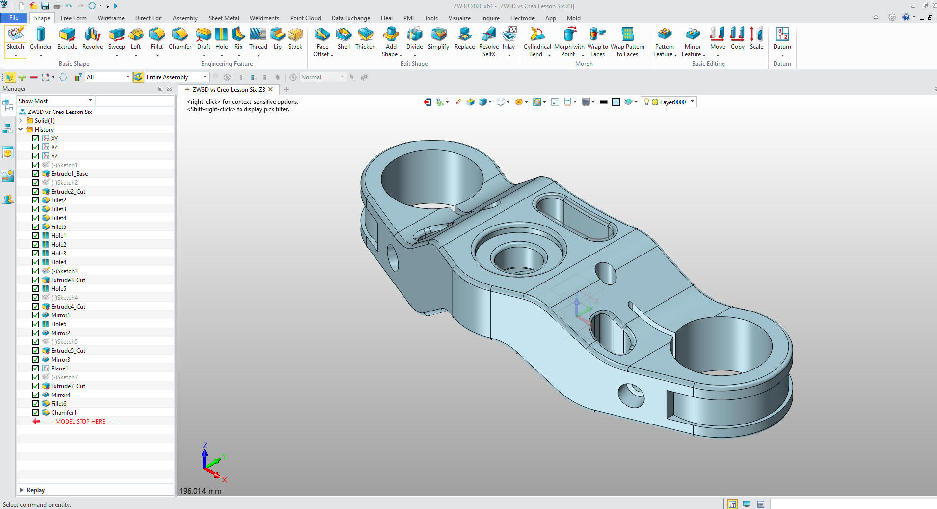
realized that I design in shapes. ZW3D has primitive shapes and
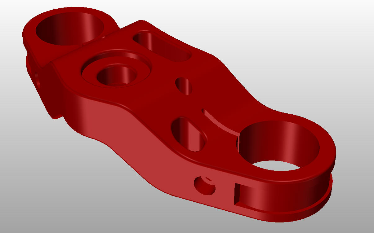
robust direct edit functionality. I look at the drawing and pick out
the basic shapes of the part instead of creating a sketch. You can see that in this part.
Many of these modeling techniques can easily
be implemented even within the most Solidworkish of systems. I call
it Streamlined Sketching and Feature Based Modeling. Please review a
few of the above ZW3D vs these other systems, there are some very stark differences.
Please watch
a Creo user model this part! I really think that Creo cannot be a
complicated as this user makes it. I use two sketches, two
extrusions, one primitive cylinder, 5 holes, 4 fillets! Except with
the primitive shape, which would be a simple extrusion, any system can do
this like I did in ZW3D.
Technique, technique, technique!!
With all the
tedious constrained
sketching for this simple part for the Absolute Beginner, you can imagine a
complex part?
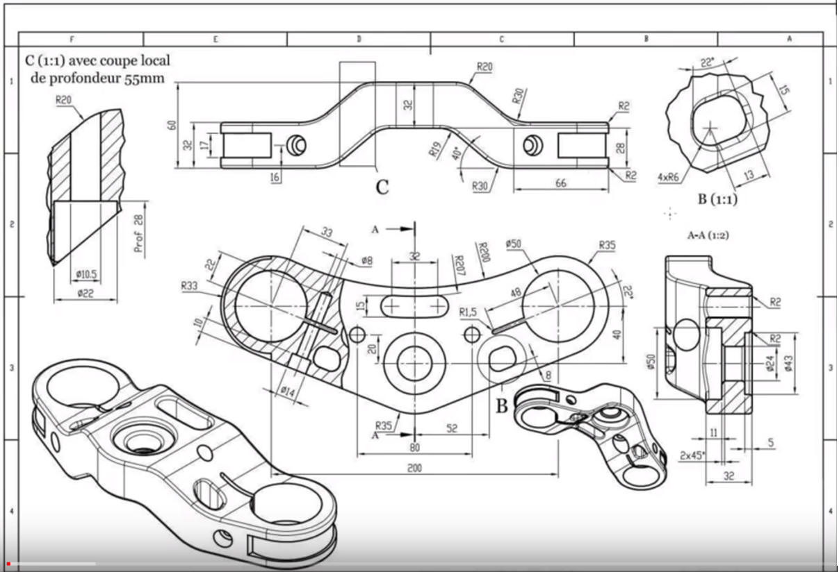
Here is the drawing so you can create this part. You can also
use the video for more detail.
While creating 3D models from drawings is the very best
way to learn 3D CAD and maybe some design techniques it does not
expose the designer to the design flexibility necessary in design. IronCAD is all top down due to the single model environment.
Creating mating parts is a cruise. But modeling is just one aspect of a
well designed productive 3D CAD system.
Creo
is a marginal 3D CAD system based on the dated Pro/e history
based modeling system released in 1988. I sold Pro/e years ago
and found it not productive enough
for our engineering department. We use what we sell. That gives us
the experience to effectively support our user base.
I would do a
video, but I really am not good at it. So I will show you step by
step. I will try and get ZW3D support to create one. They are
very good.
The modeling technique is hugely responsible for
the level of productivity. Those of you that are only trained in the
sketch, sketch, constrain, constrain world are truly limited by not
using the freedom of feature based design, that is available in even
the most Solidworks-ish of CAD systems. If your
designers are designing in these very unproductive and time
consuming processes it might be time to review your standard design
processes. Don't have any do you?
These lessons have actually turned into exercises in
modeling techniques as compared to showing a more productive CAD
systems. Again, I say, there are many different ways to model a part.
I see with my exposure to direct edit modelers like CADKEY, I
rarely sketch like you see the Solidworks fellow doing. I have always
created my basic sketches by mostly creating offsets and extending
and trimming or. It seems to be much easier. I never put in a fillet that
can be created later. What do you think?
Since ZW3D
is a sketch based product with a primitive shape option I will
create the model in both processes. The sketched based model will be
done with StreamLined Sketching to show the incredible simplicity
and productivity over the de facto constrained sketching.
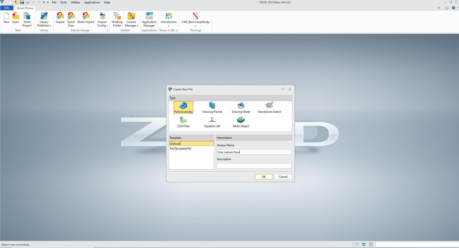
I
create a new Part/Assembly file.
Note: When doing production
design you can use the Multi-Object file to create a part file under
a top file. You then could keep a legacy of modifications or similar
parts in a single file
We are already in
millimeters. So we can start modeling.
I
create the first sketch on the XY plane
For the life of me I
do not know why we start throwing in graphics of the basic shape and
add constrained dimension instead of just defining the features as
we create the sketch.
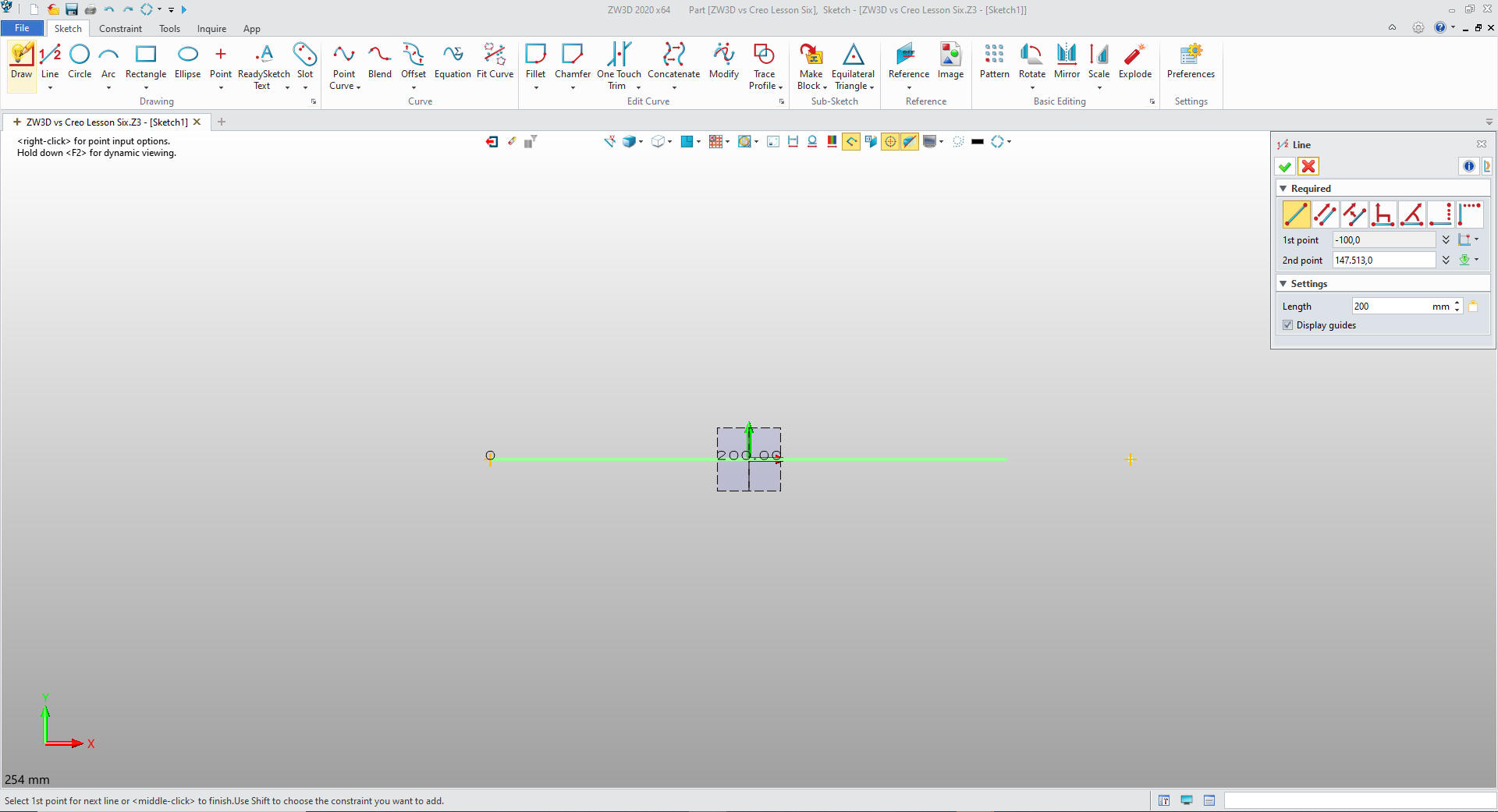
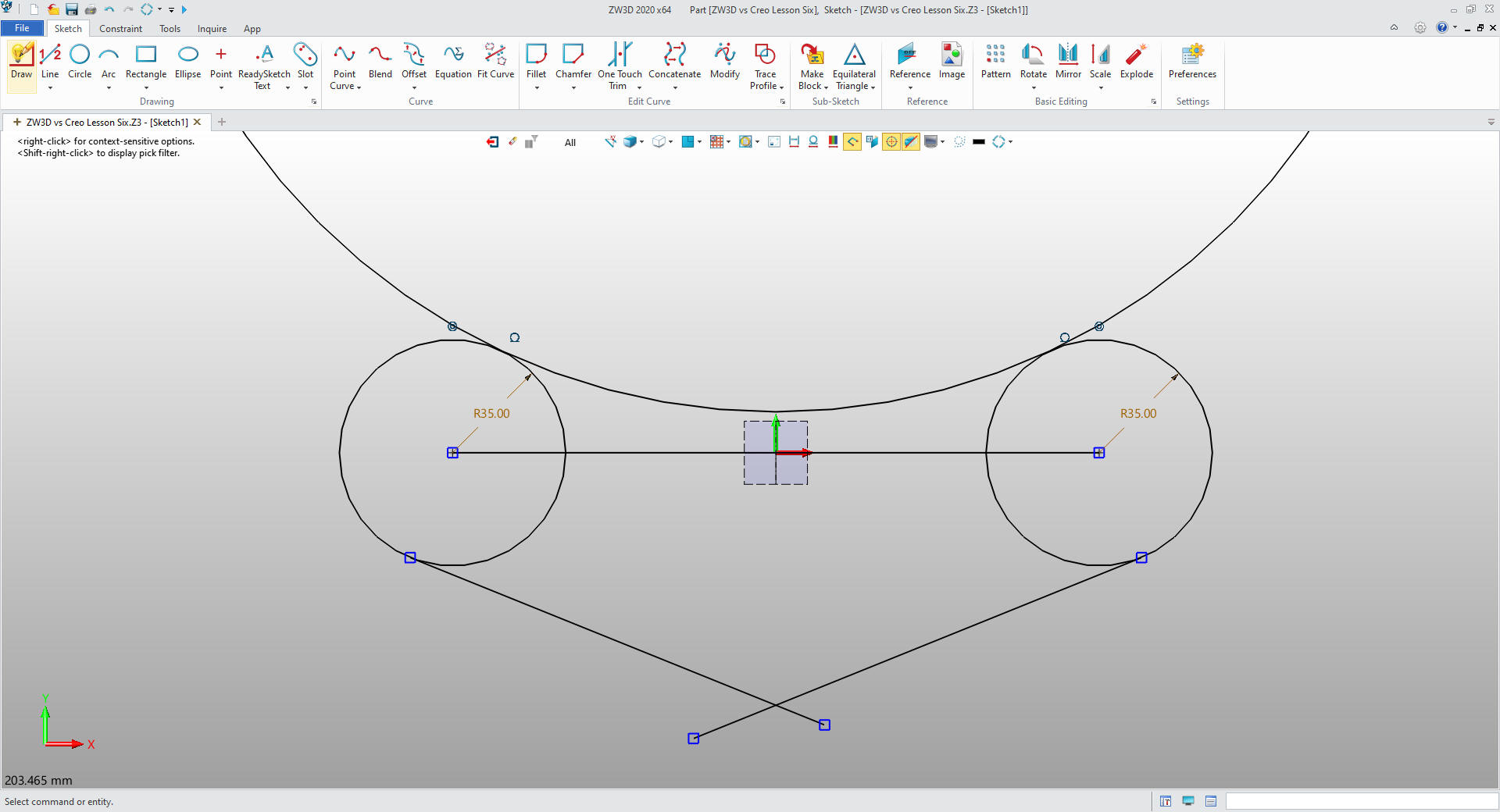
We first create a construction line
centered a X0Y0Z0. I just use graphic entities for construction and
will delete them before I save the sketch
I
create the two 35mm circles with one command on the ends of the
line. I then create the two 22 degree tangent lines also in the same
command. I then create the circle with two tangent points and the
arc. 3 steps!!! Not one constrained dimension.
The Creo presenter takes over 3 minutes to create this sketch, it
starts at 6:22 ends at 9:35. It is only 5 entities plus my
construction line. I do not throw
in some graphics and constrain them I define them as I put them in.
This is what I call StreamLined Sketching and Feature Based
modeling.
From less than a minute to 3 minutes? I doesn't
sound like much savings but think of a complex part. It can turns
into hours of savings!
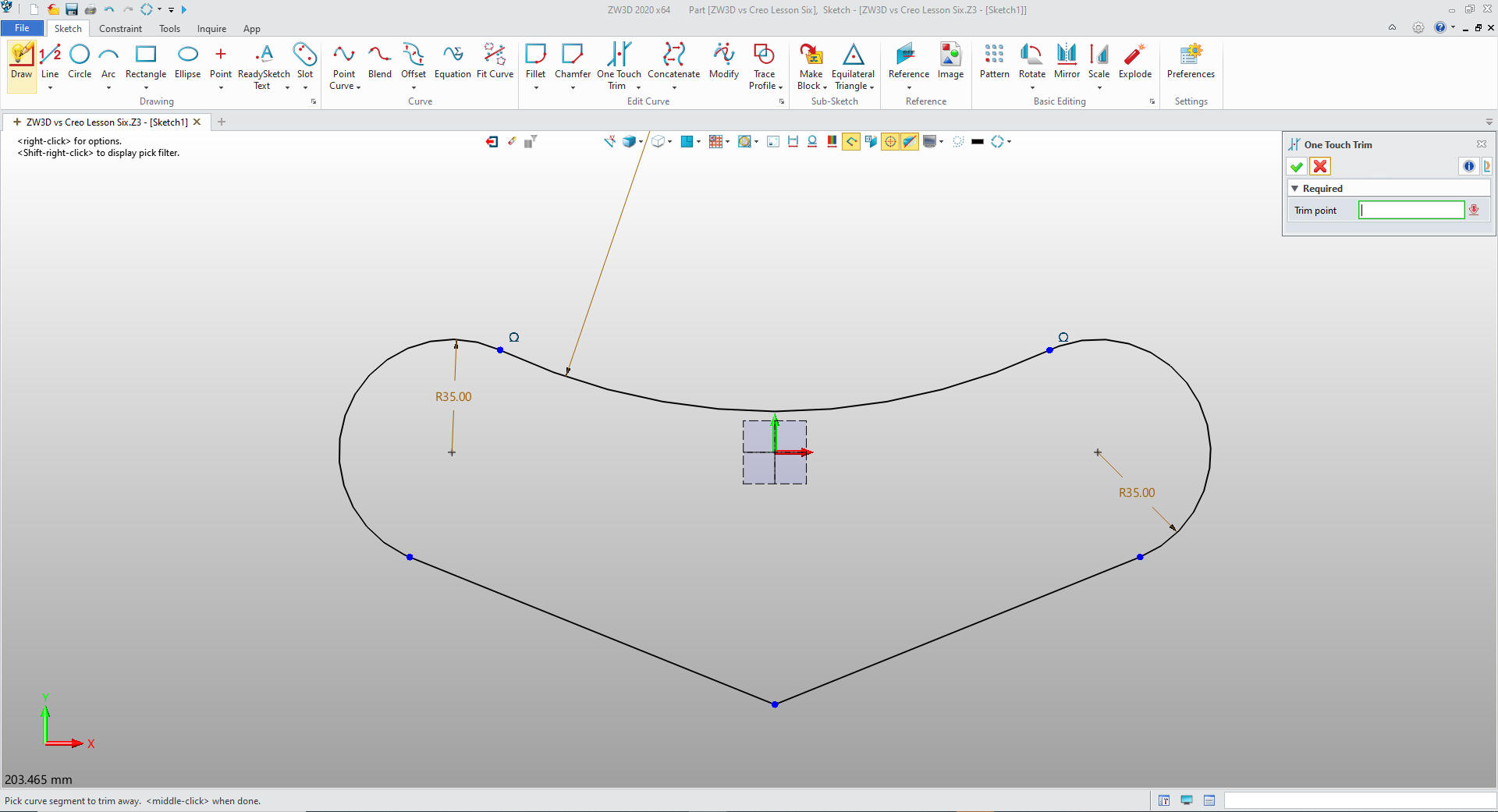
We just delete
the one entity used for construction and trim/extend the necessary features
and were are done with our sketch. I do not put in the blend on the
bottom I will put it in later.
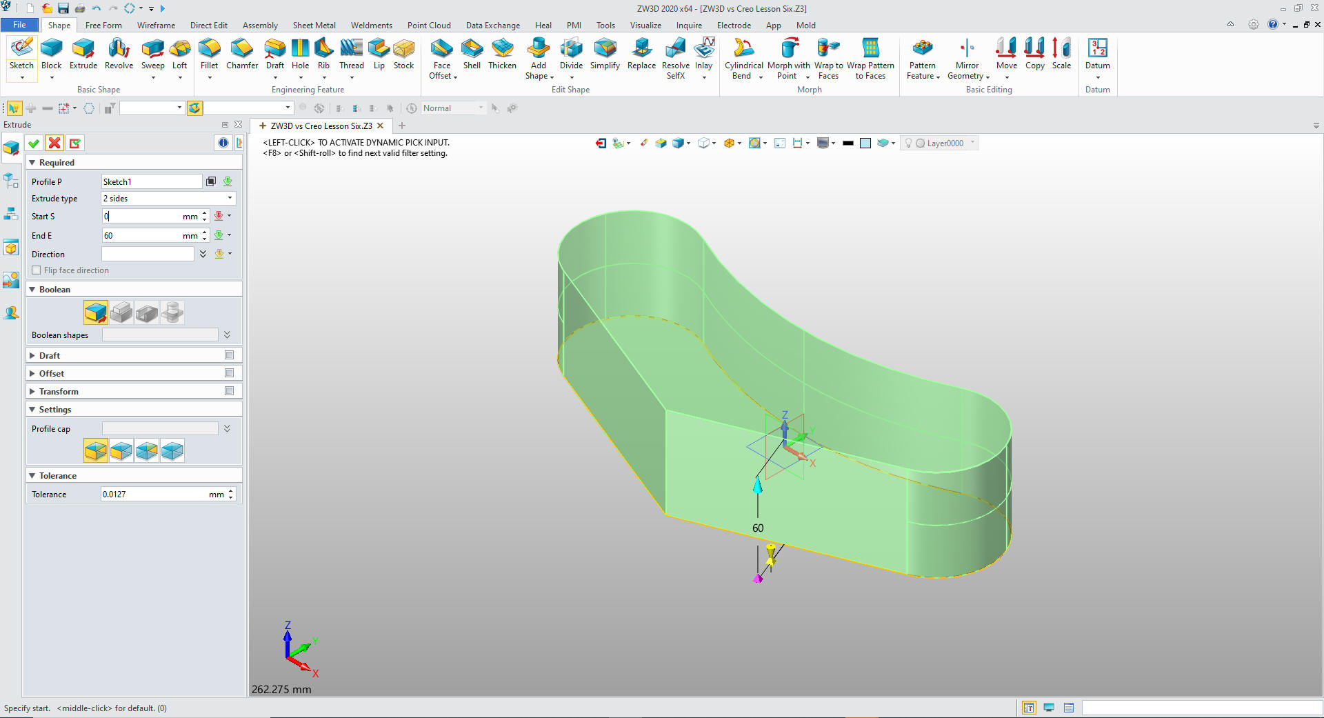
We
exit the sketch and extrude the profile!
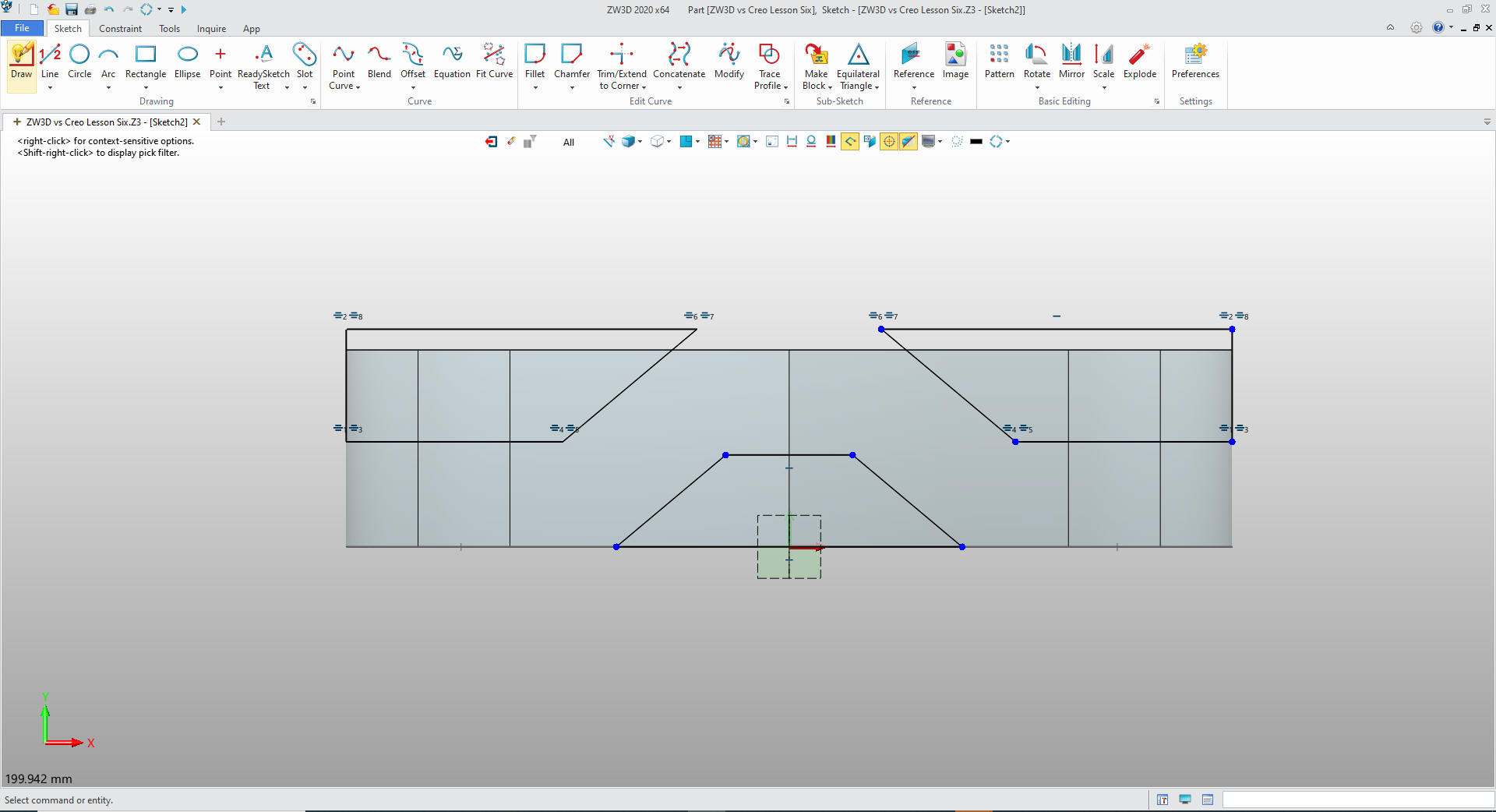
We create a sketch on the XZ plane and
create our sketch to make the cut.
I sketch the profile by
creating lines and offsets directly. I trim or extend the lines.
Again no constrained dimensions.
We exist the sketch, extrude the profile set to remove.
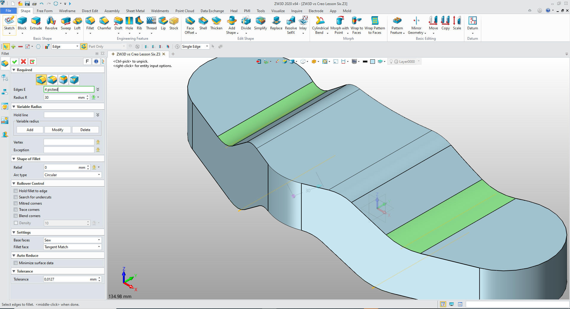
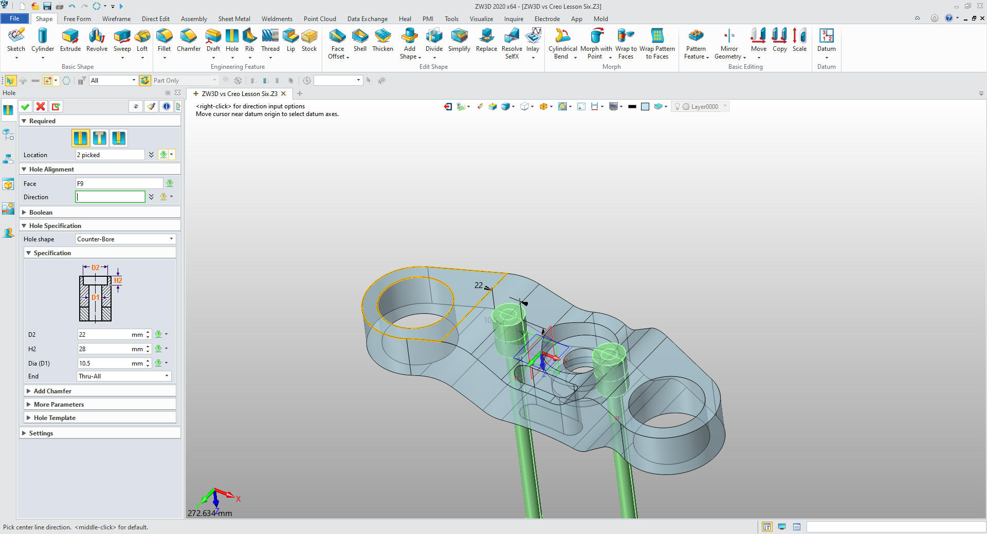
We
create the major fillets
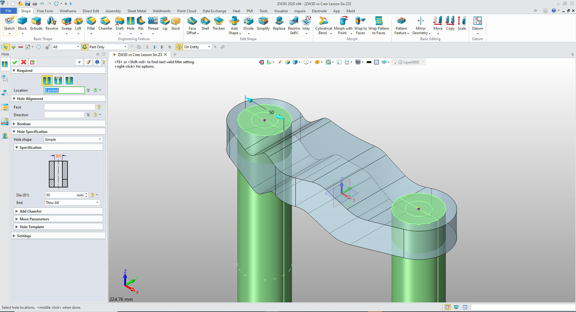
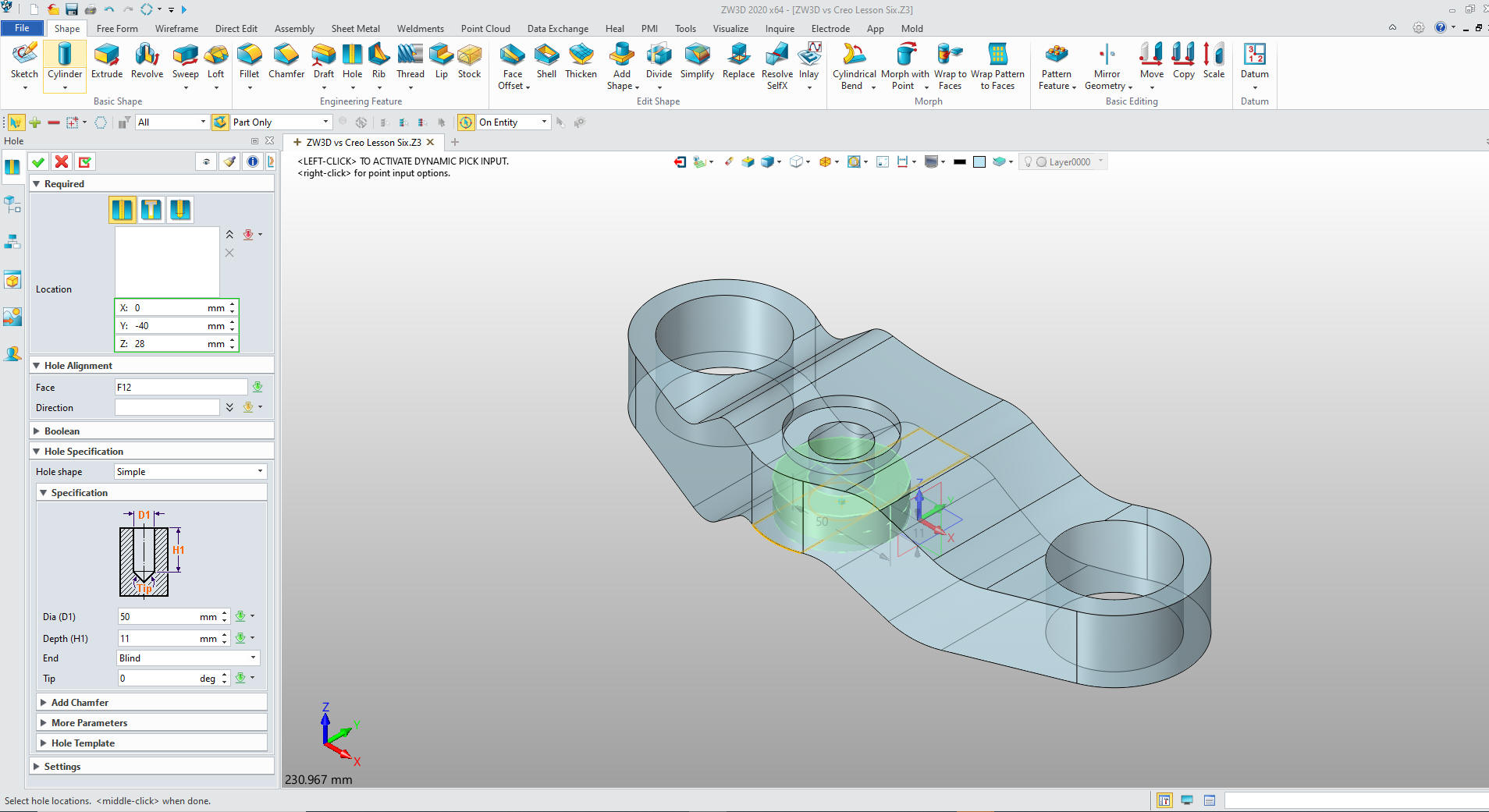
Using
the Create Hole Feature we locate the two 50mm holes.
Watch
the Creo presenter select the face create a sketch create a circle
constrain the circle around 14:30 into the presentation. I know Creo
has hole creation features, why doesn't he use them. He thinks of
constrained sketching first!
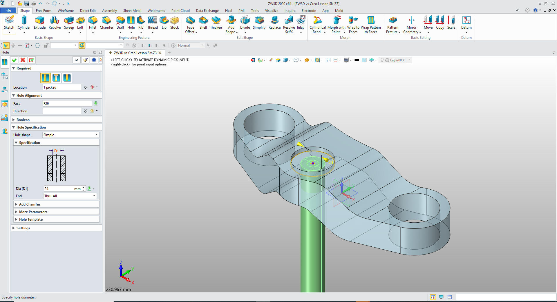
We
create a YZ plane at the center of the cylinder.
We
create the second hole at the center of the existing hole set the
diameter and select through.
We create the hole size and located it explicitly! No thinking
at all.
Watch the Creo presenter go through and incredible
convoluted process of creating a custom hole and locating it. Then
some sort of process to make sure it extends through the fillets. I
don't know if he even cleans them up later you see them when he adds
a fillet.
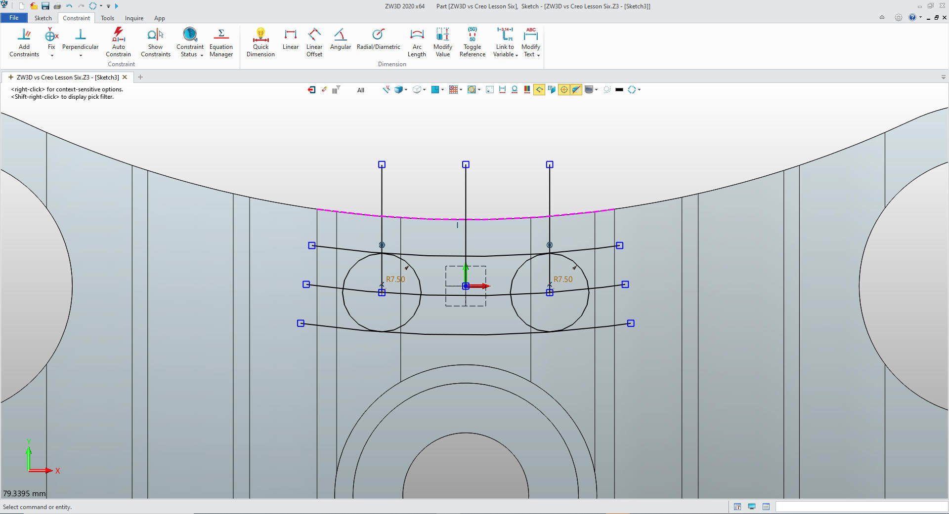
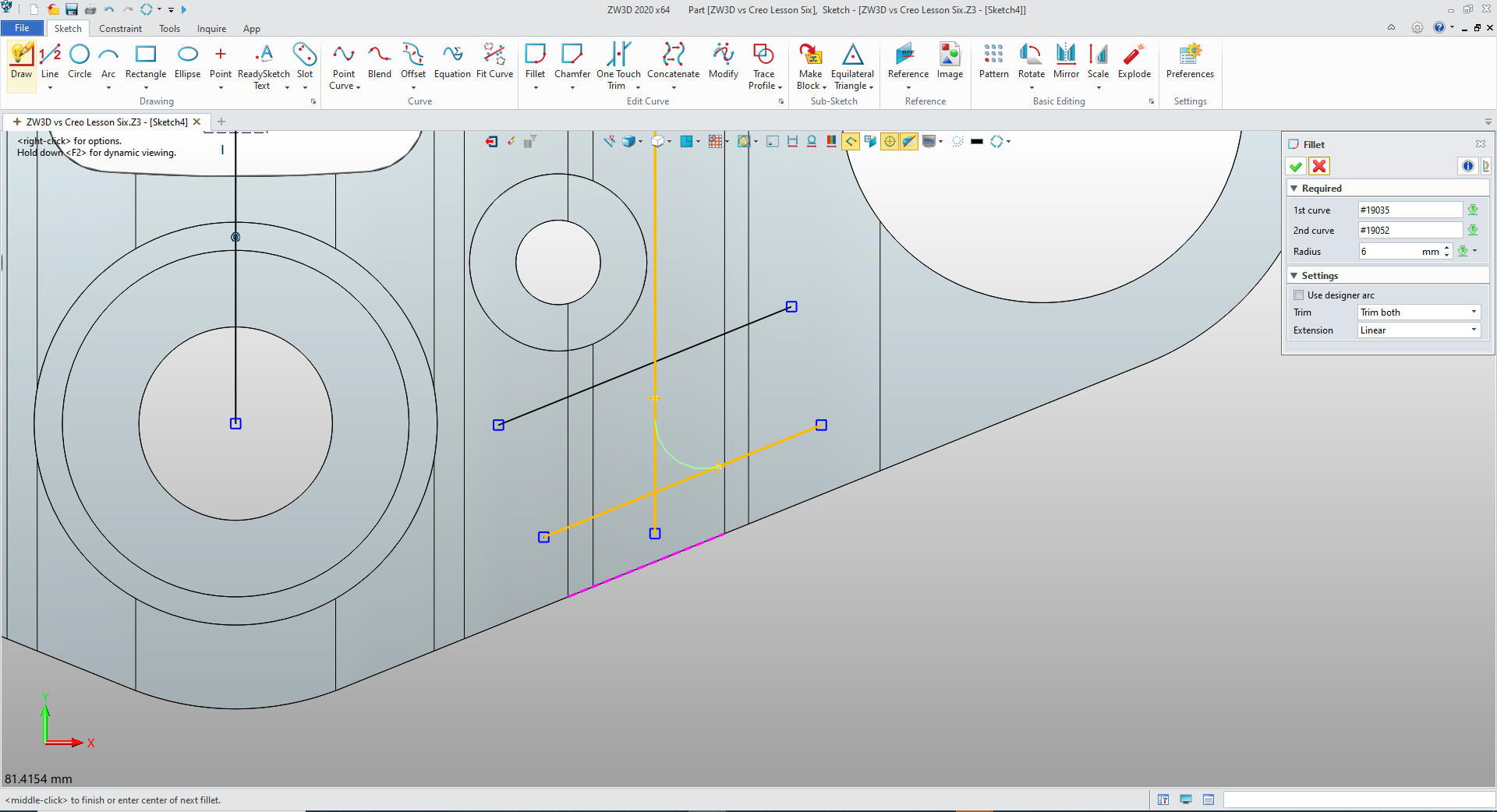
We project the top edge and create 3
more offsets of the arc. We create a centerline and do an offset on
both sides. We they put in our circles at the pertinent
intersections. Again no constraints. This is StreamLined Sketching.
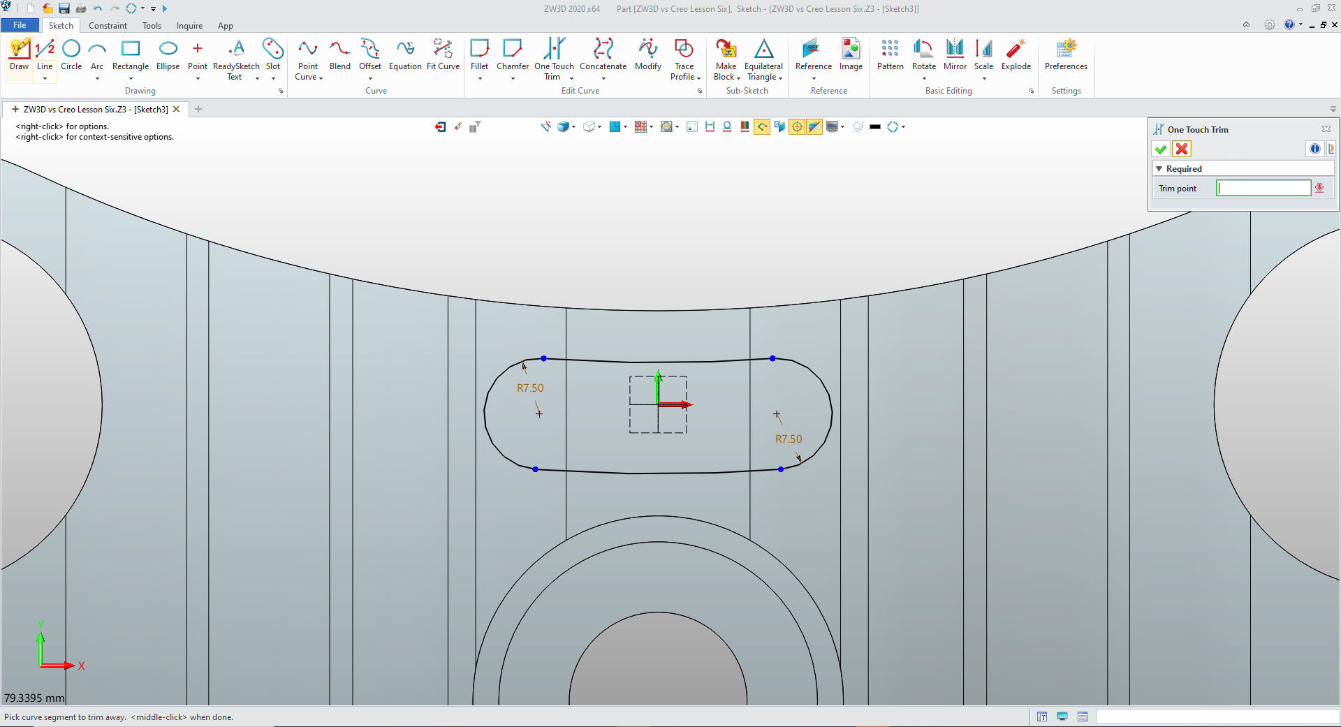
We
delete the construction entities and trim the others.
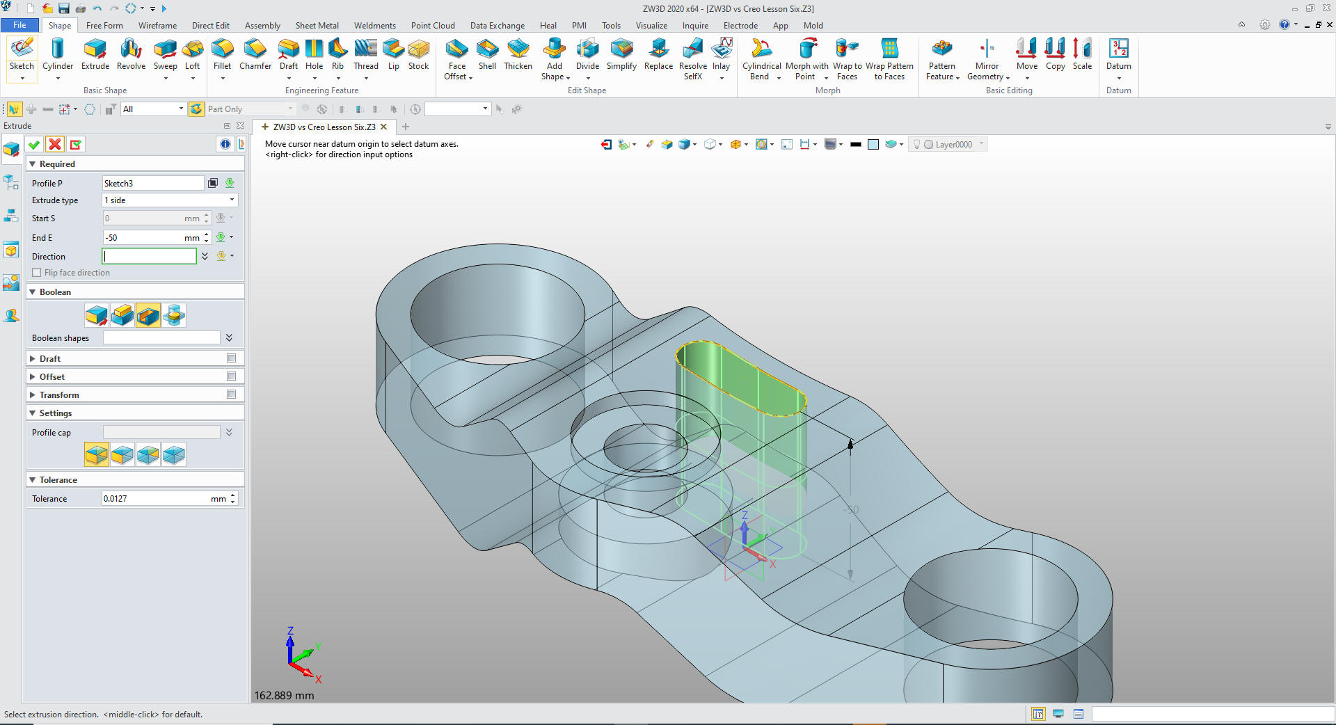
The
Creo race track feature is very clever. Who da thunk it?
We exit the sketch and extrude the profile.
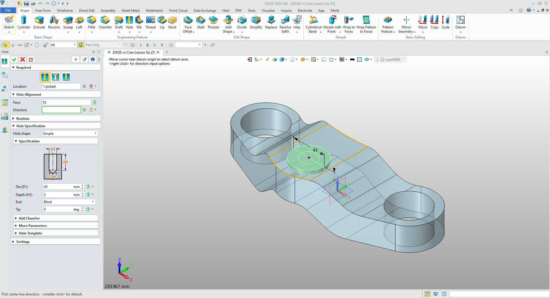
Again
we use the Create Hole Feature for the two counterbored holes. They
are from the bottom face of the large hoes. We use the center hole
for the location. We put both holes in with one command.
Now for the life of me I do not know what the Creo presenter is
doing to create these holes it is around 26 minutes.
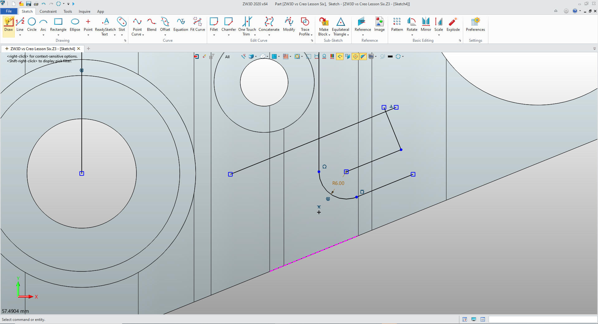
We create a sketch on the top face create a vertical and edge
reference lines and create our offsets, add the radius for our
reference location. and
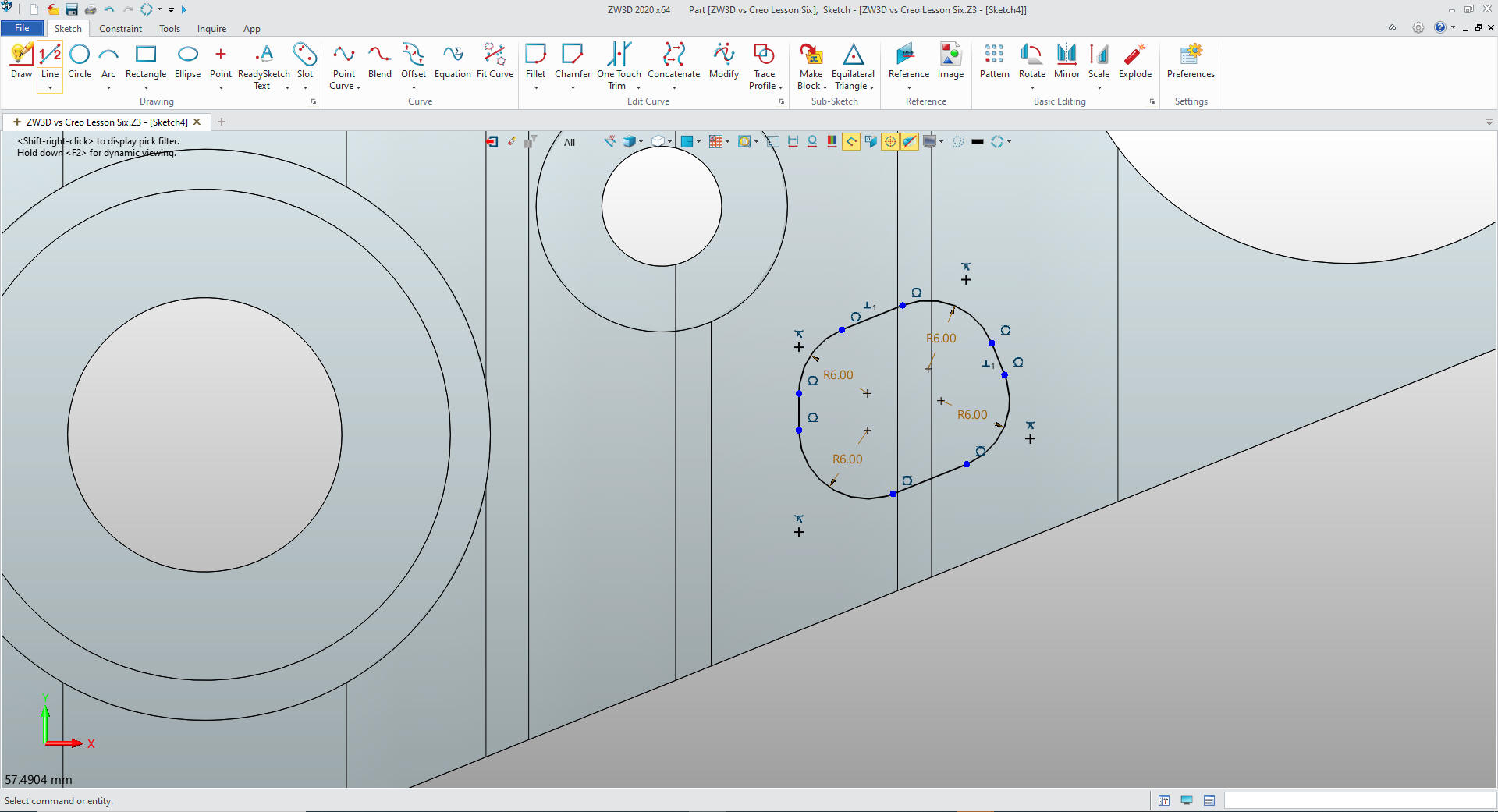
We
can now complete the sketch.
I
will add fillets here, usually I put all fillets in separately, but
we have an existing fillet so it makes a bit of sense. I well delete
the construction entities.
We
exit the sketch and extrude the profile. Since you now understand
how an extrusion is done, I will also mirror the feature by on the
YZ plane.
I know the Creo presenter mirrors all of the
features later. I like to keep my steps in order. I just guess it is
just the way I think. I always know Mr. Murphy is watching over me.
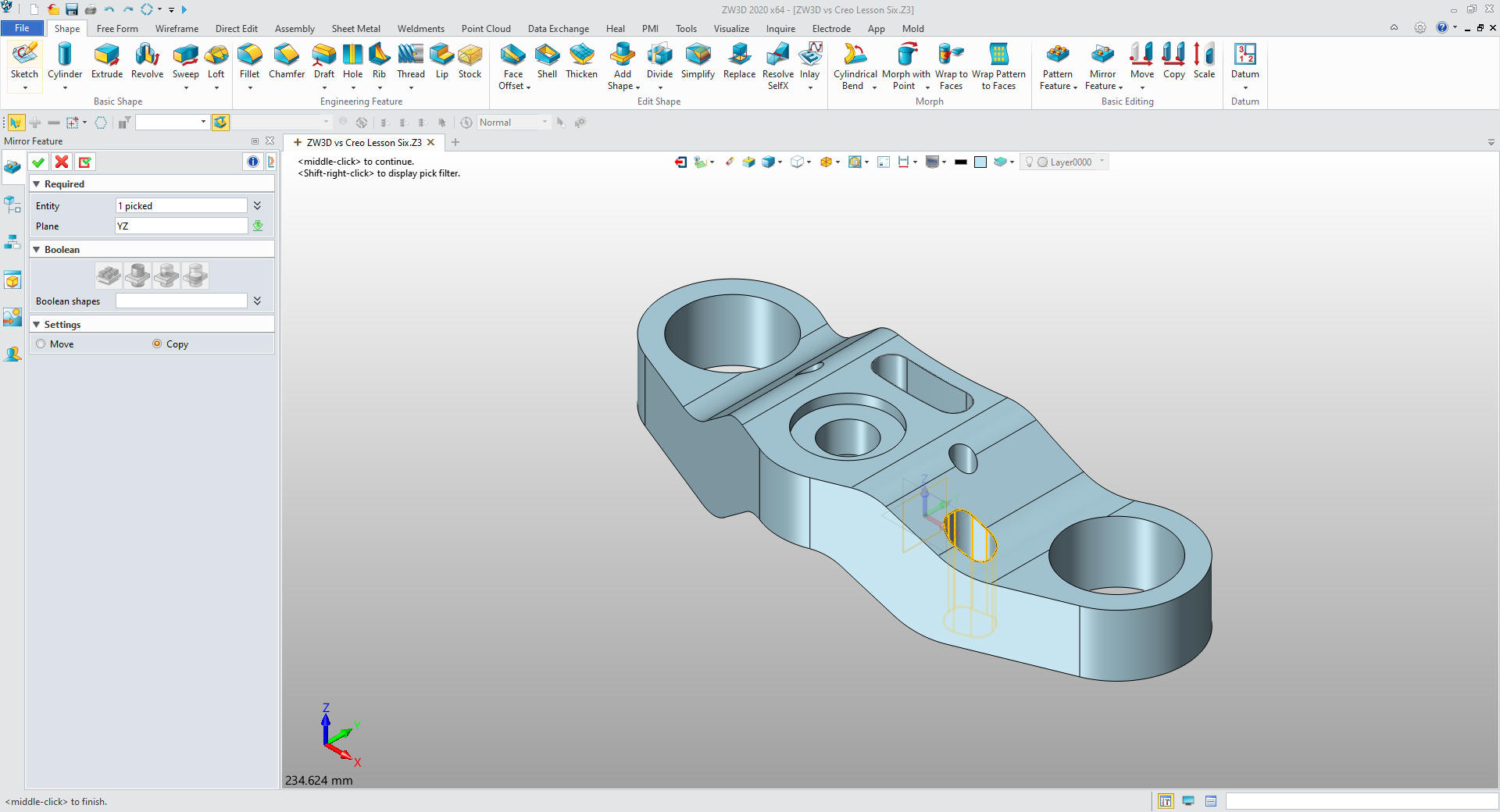
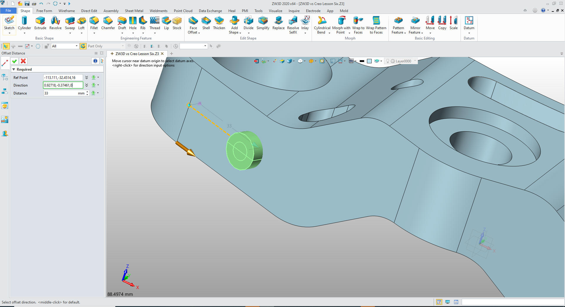
Now for the counterbored hole on the front face. We define the hole
and offset it from the mid-point of the tangent line.
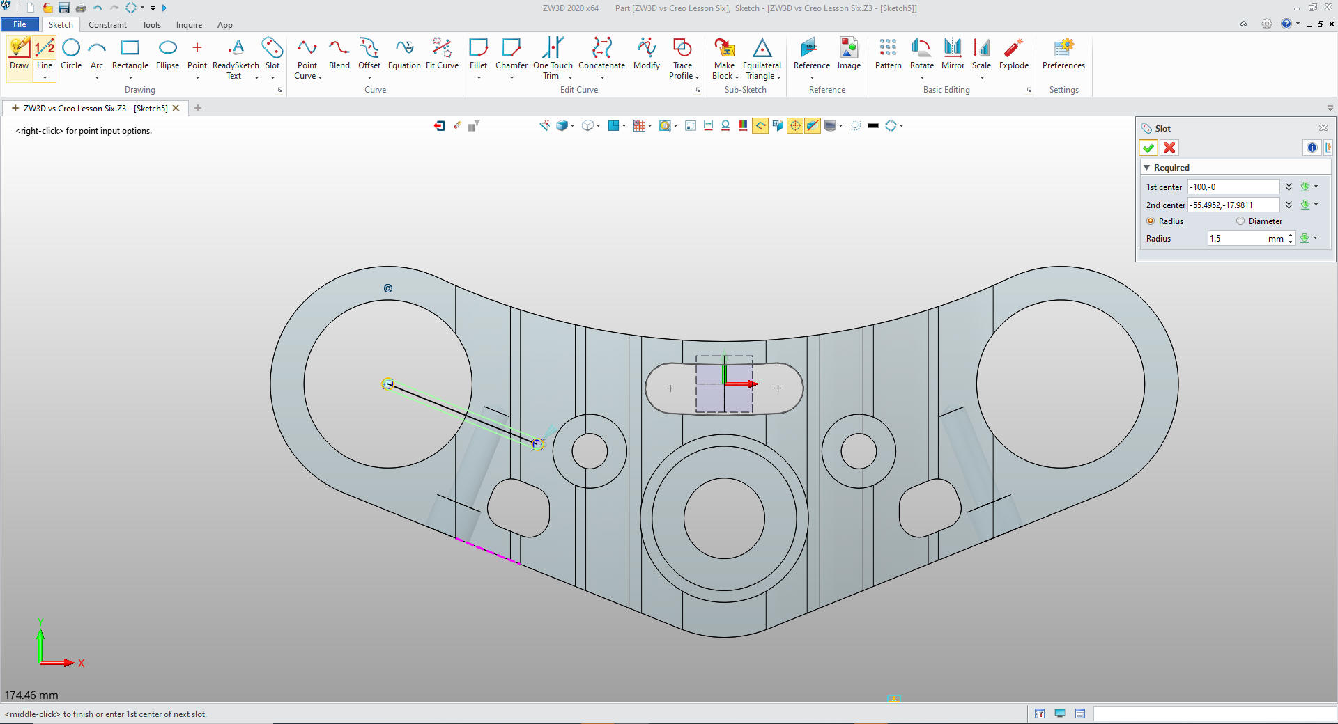
We
mirror the feature and we create a sketch for the slot. We create a
couple of reference lines then use the slot function.
We
extrude the feature and mirror it.
We now create an XY plane
at the mid-point of the tangent on the right left front face and
create a sketch.
We
exit the sketch and extrude the profile and mirror it.
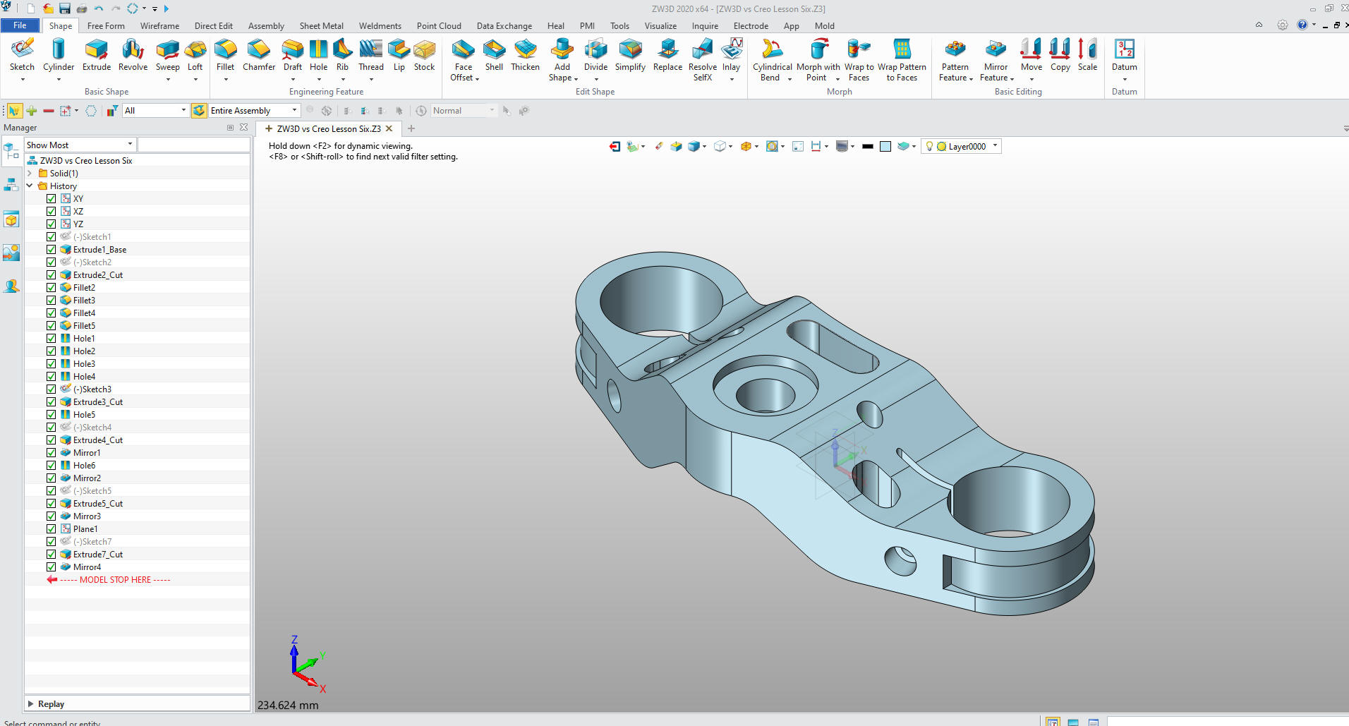
Now
for the fillets and two chamfers and we are done. Just so much
easier, simpler, faster and more pleasant than the poor Creo
presenter.
Give me a call if you have any
questions. I can set up a skype or go to meeting to show this part
or answer any of your questions on the operation of ZW3D. It
truly is the Ultimate CAD/CAM System.
If you are interested in adding professional
hybrid modeling capabilities or looking for a new solution to
increase your productivity, take some time to download a fully
functional 30 day evaluation and play with these packages. Feel free
to give me a call if you have any questions or would like an on-line
presentation.