ZW3D vs NX Lesson One Assembly 3D Modeling Techniques Defined
True Top Down Assembly/In Context Design In a Multi-Object Design Environment With Streamlined Sketching/Feature Based Modeling
The modeling technique is
hugely responsible for the level of productivity. Those of you that
are only trained in the constrained sketching world of the major CAD
systems
are truly limited by not using the freedom of Streamlined Sketching
and Feature Based Design,
that is available in even the most Pro/e-ish of CAD systems. If you
or your
designers are designing in these very unproductive and time
consuming processes it might be time to review your standard design
processes. Don't have any do you?
These
lessons started out as
product comparisons, but quickly turned into a study in 3D modeling
techniques.
I am not sure if it is due to these
exercises but I have replaced a few Creo, Solidworks and Fusion 360 with ZW3D. Listen to
what these two fellows said.
Brian
"We spoke a year and a
half or so ago about ZW3D. I took the Autodesk Fusion
360 but am becoming increasingly unhappy with it… It’s not very
productive for me, just too slow and cumbersome to get things done
quickly. On on the strength of your recommendations I am ready to
give ZW3D Standard a shot, probably as a rental for the first year.
Bottom line is,
Fusion 360 is “free” but not really free… I am finding that the
slow, clumsy pace of design with it is counterproductive… time is
money."
Thanks much,
Brian
Peter
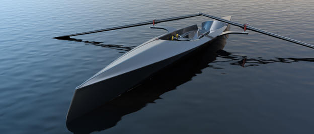
The initial hull design was done in Rhino, which for some reason
is a standard in the boat industry.
The surface already had
a few problems!
It was imported into Fusion 360 and I did
some of the early concept design work, but when it came to surfacing
I hit road blocks every way I tried it.
At this time Phil
was not part of the project, but I suggested to my client that we
needed Phil's help. Phil also hit road blocks in Fusion 360 even
using some of his unique re-topologizing workflows and T-Splines.
The rest is history, as they say.
Thanks to ZW3D
paired with Phil’s surfacing skills we now have tooling for the hull
created.
You should see the images.
Perfectly smooth
reflections!
Peter I saw the
following NX YouTube tutorial and thought I would give it a
try on ZW3D. I have to tell you it is almost tortuous to watch
the NX presenter. I
have tried to do top down design in Solidworks and failed. Inventor
is a bit better but all of these programs including NX create
external parts. You will see a huge difference in ZW3D's
multi-object design environment.
NX is a constrained sketched based
system as are Fusion 360, Solidworks and Creo. In the following
lessons you can see that this modeling paradigm is use throughout
the industry causing millions of wasted hours.
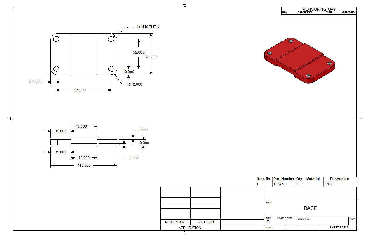
The reference drawings are at the end of the lesson.
While creating 3D models from a drawing is the very best way to
learn 3D CAD and maybe some design techniques is does not expose the
designer to the design flexibility necessary in product design. ZW3D is all top down due to the
multi-object design environment.
Creating mating parts is a cruise. But modeling is just one aspect of a
well designed productive 3D CAD system.
ZW3D vs NX
ZW3D is very similar to
NX and the Pro/e
clones with differences that make it much more streamlined. It is very easy for those users
to get up and running with ZW3D. The unique benefits over the other systems
is the multi-object environment with the integrated drawing. You can
do complete projects (parts, assemblies and drawings) in one file.
I would do a
video, but I really am not good at it. So I will show you step by
step. I will try and get ZW3D support to create one. They are
very good.
The modeling technique is
hugely responsible for the level of productivity. Those of you that
are only trained in the constrained sketching world
are truly limited by not using the freedom of feature based design,
that is available in even the most Pro/e-ish of CAD systems. If your
designers are designing in these very unproductive and time
consuming processes it might be time to review your standard design
processes. Don't have any do you?
ZW3D is a history based
system with planes, but it also has primitive shapes to increase
your productivity. It seems to me watching this NX
exercises that there is no concern for simplifying the process and
increase design productivity. Most of us do engineering design and
have schedules to meet. Not only do these more productive modeling
techniques and a productive system increase design speed it allows
us to meet our goals much easier. Especially with changes.
I
have to say this is incredibly simple. But the NX presenter has been
indoctrinated into these designs time consuming modeling techniques. The Solidworks clones are costing the industry millions, if not billions,
in lost productivity.
Here is ZW3D. It is set to mm so let's
get started
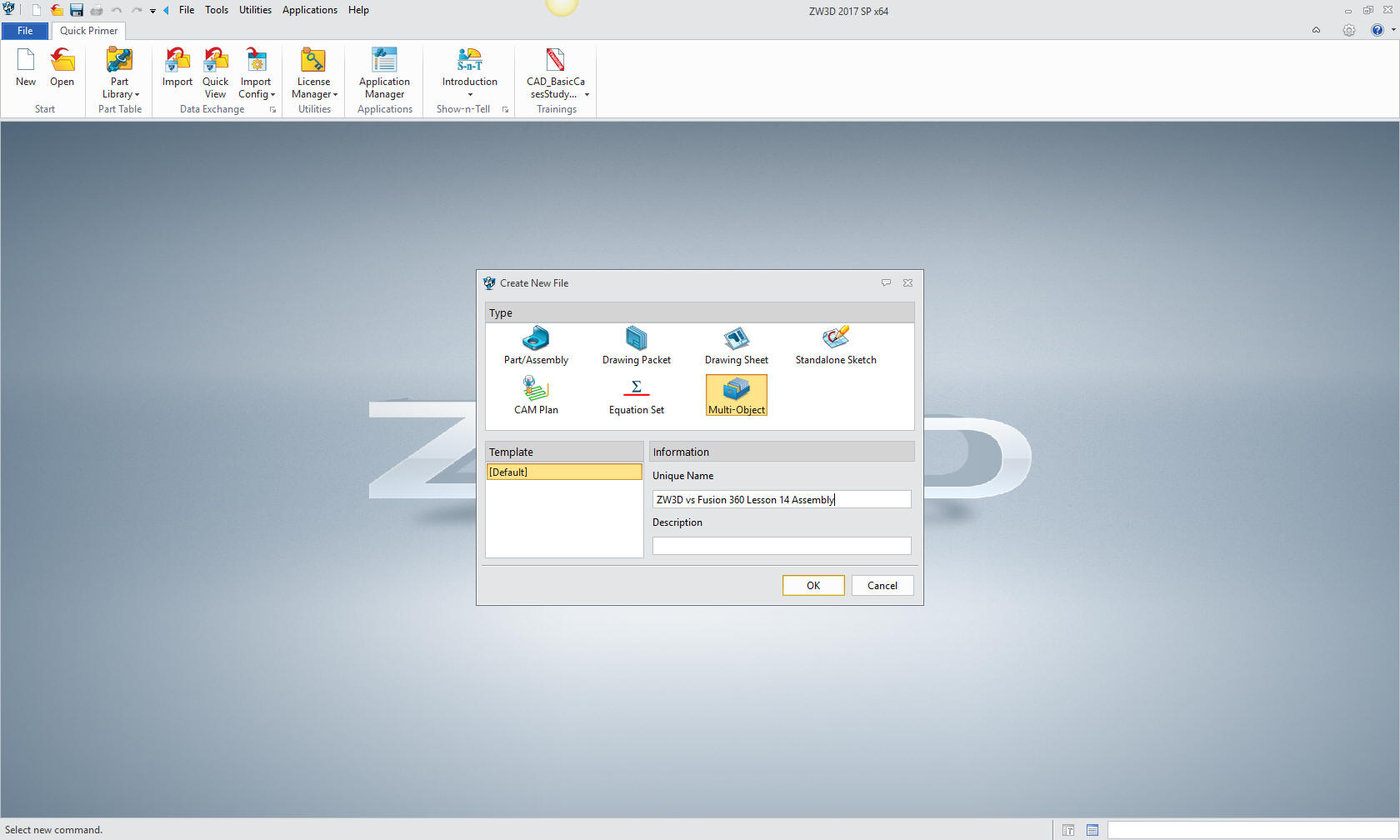
Like NX we have to set ZW3D for an
assembly. We open a multi-object file and call it Belt Roller
Assembly
These have actually turned into exercises in
modeling techniques as compared to showing a more productive CAD
systems. Again, I say there are many different ways to model a part.
I see with my exposure to direct edit modelers like CADKEY, I
rarely sketch like you see the NX fellow doing. I have always
created my basic sketches by mostly creating offsets and trimming or
extending. It seems to be much easier. I never put in a fillet that
can be created later. What do you think?
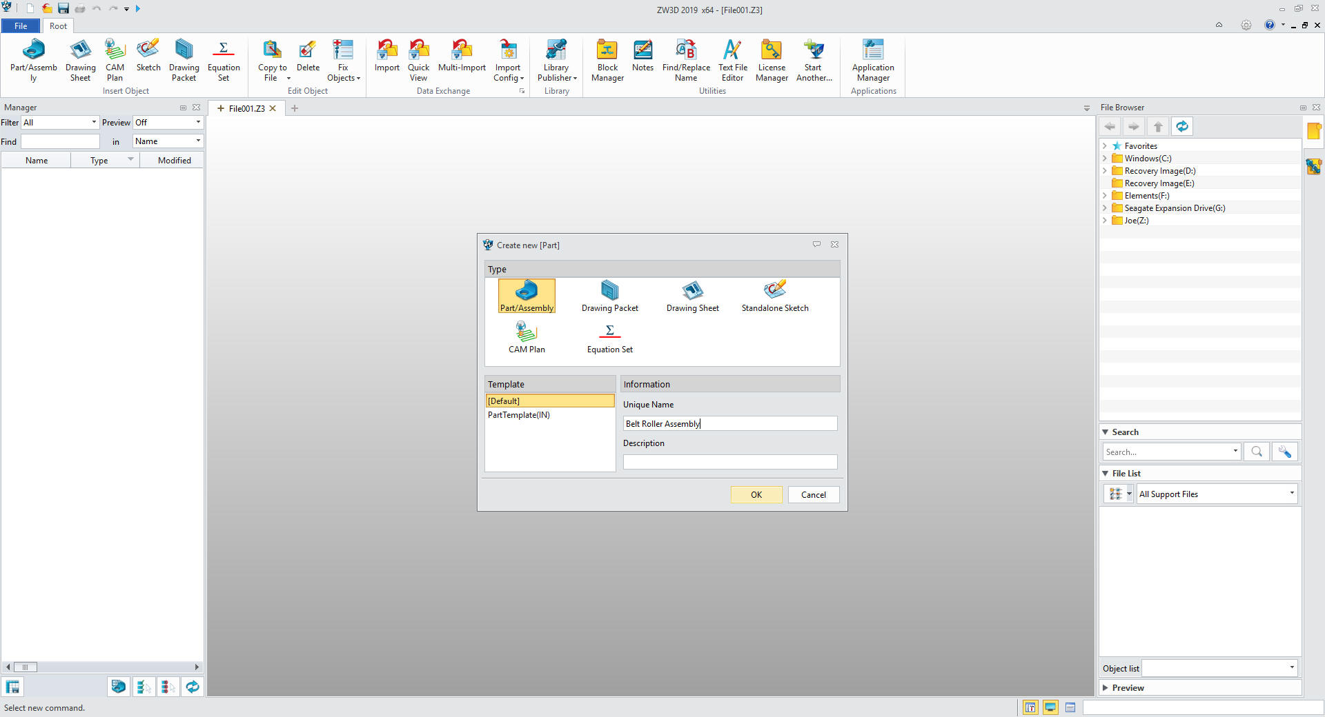
I will first create my part which will
be the top assembly and call it also the Belt Roller Assembly.
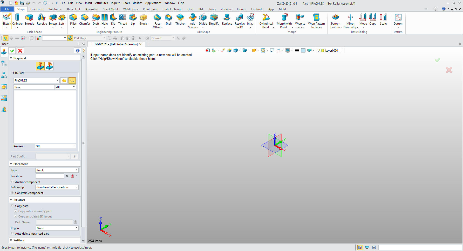
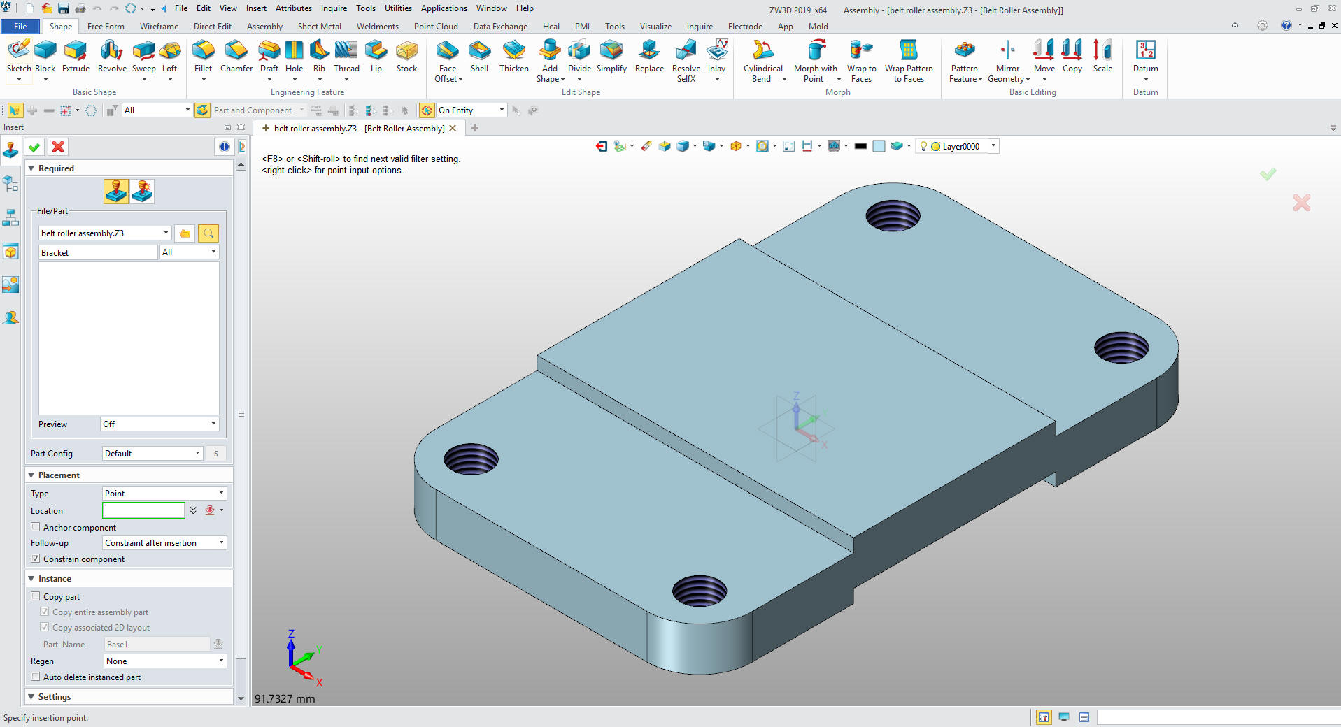
We
will now insert our first component the Base
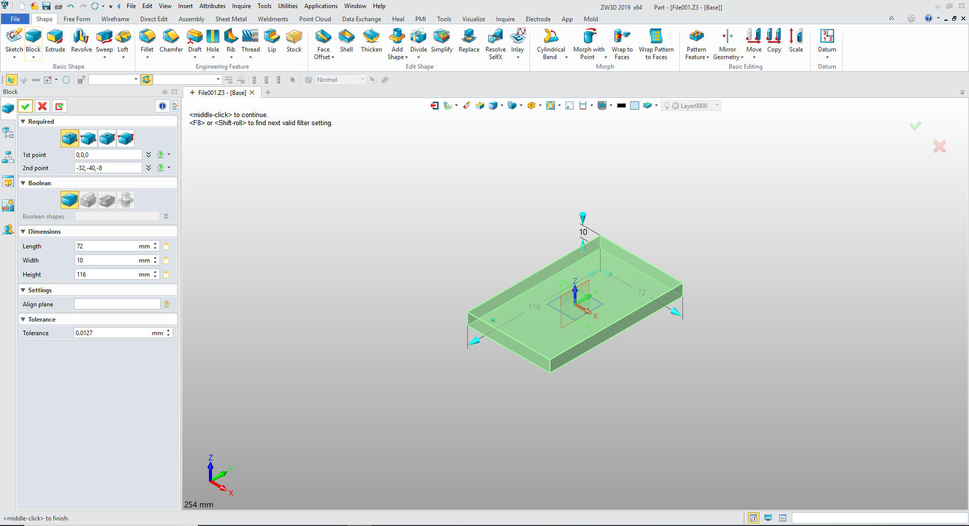
We will now
start our part by inserting a primitive block shape and sizing it.
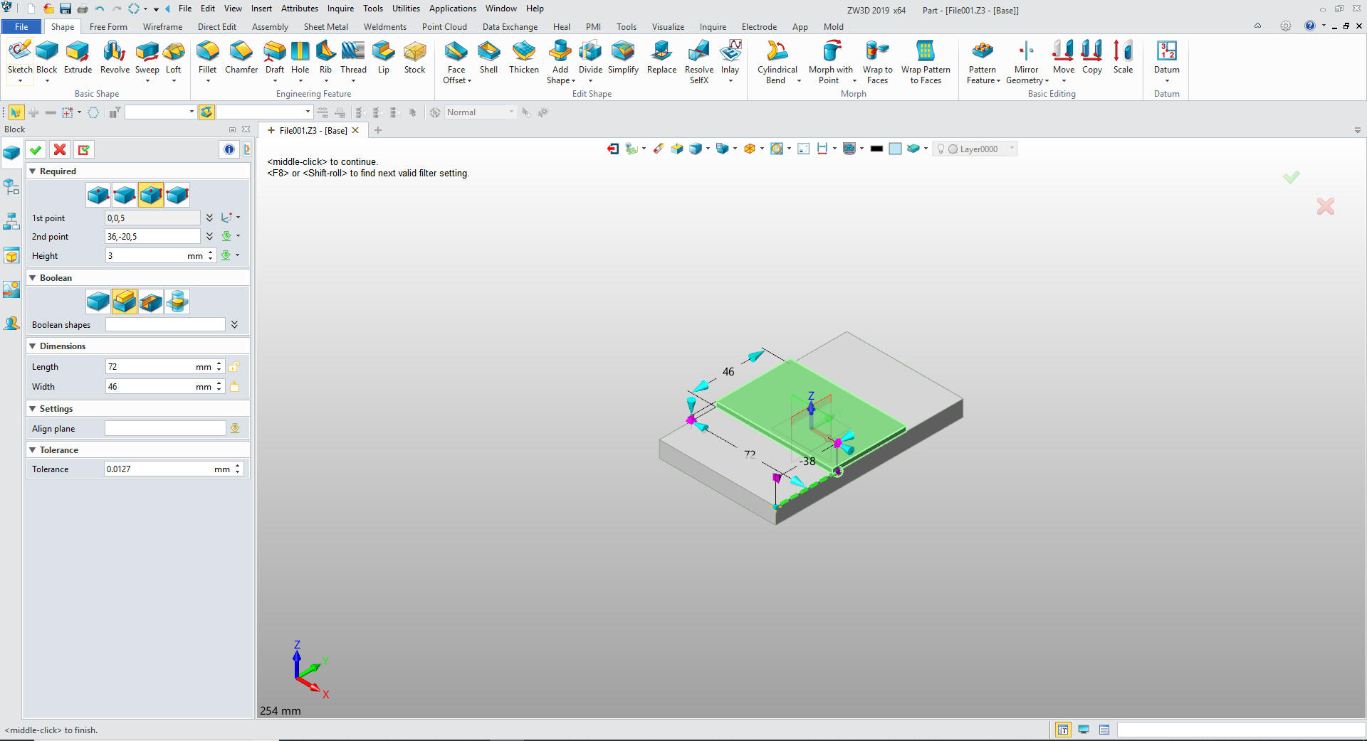
I will insert another primitive block,
size and locate it and set it to add.
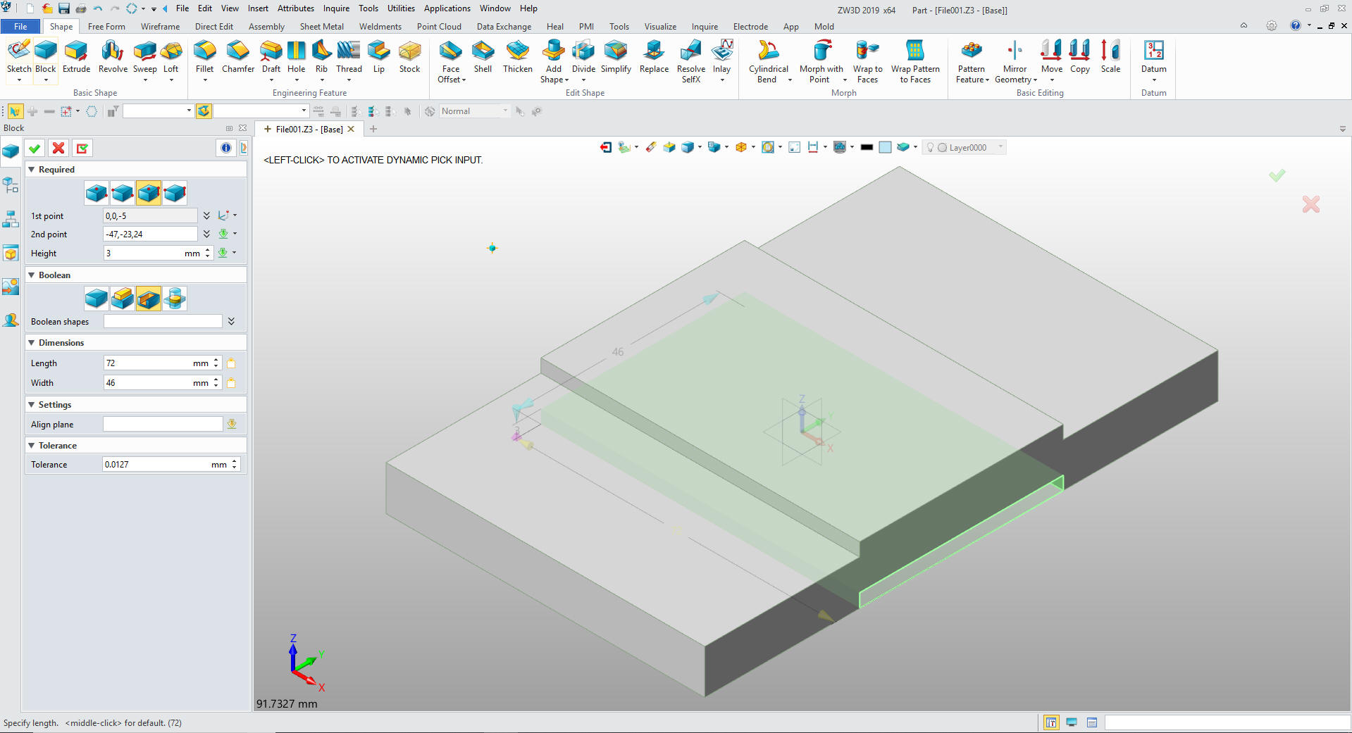
Now insert
another primitive block, size and locate it and set it to remove
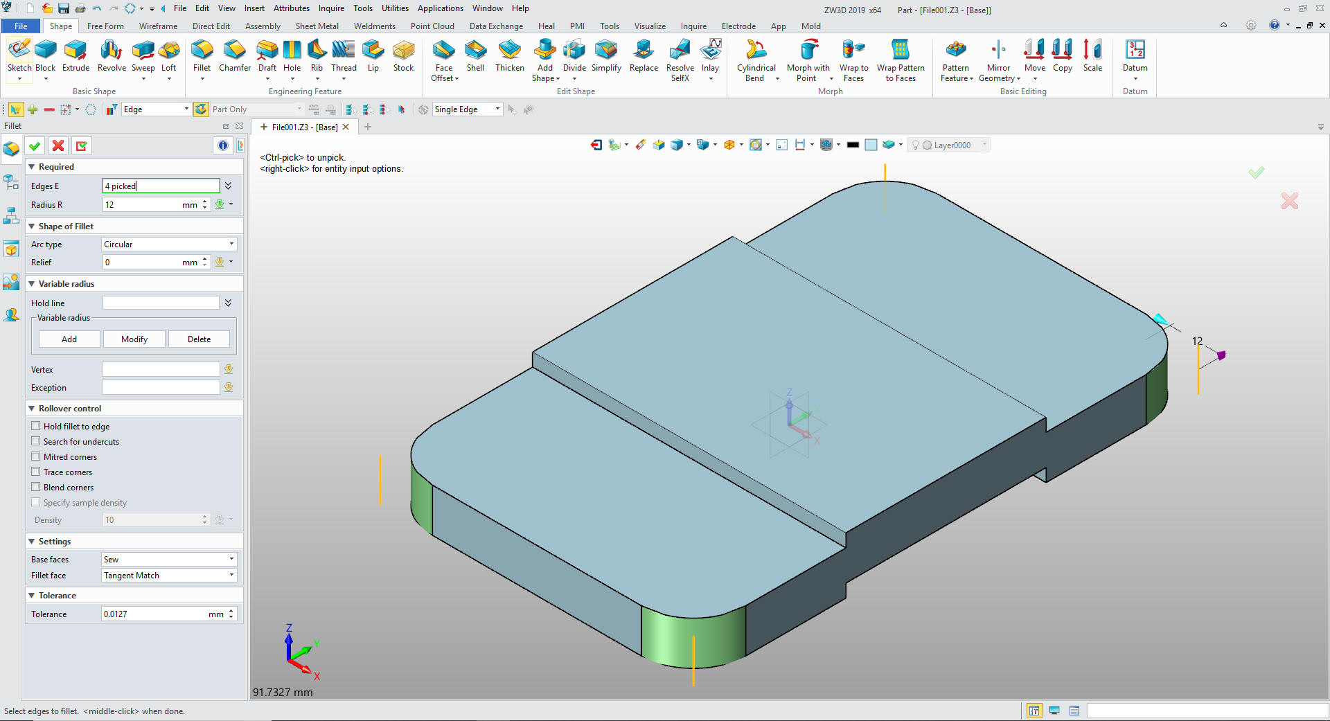
I put in the fillets.
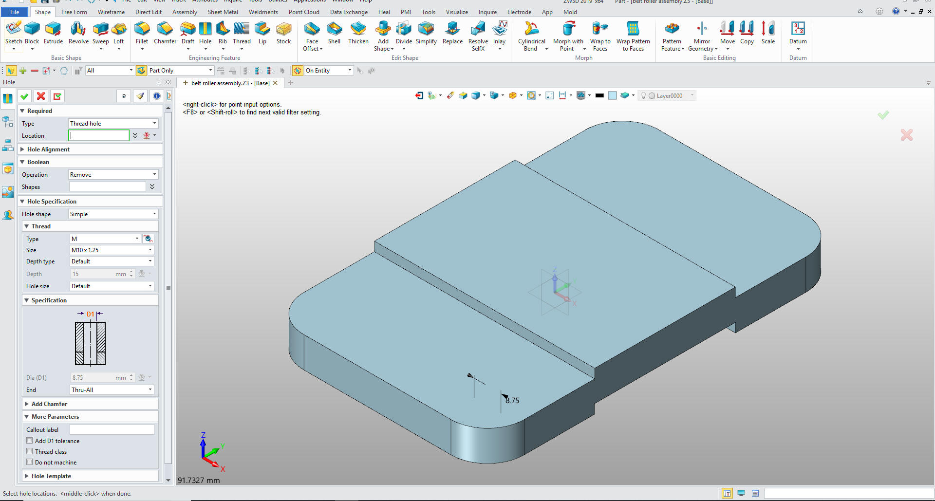
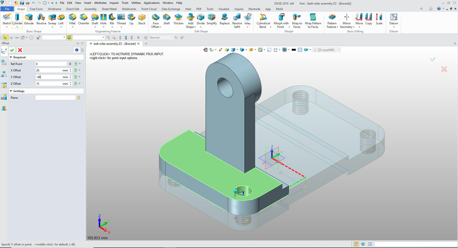
For the threaded hole we bring up the
Create Hole Feature. We set our hole specs.
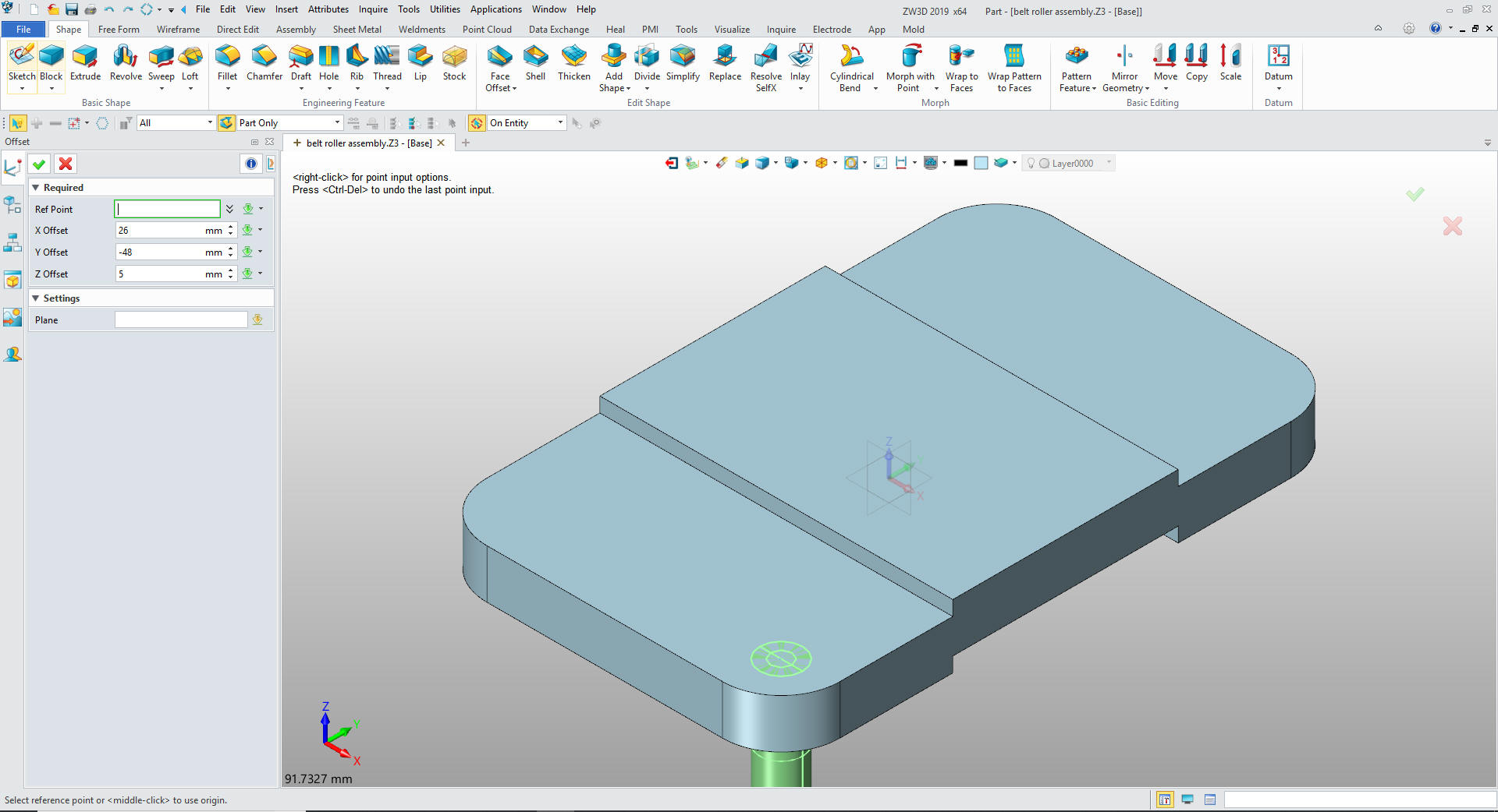
We locate the hole by selecting
offset from the options.
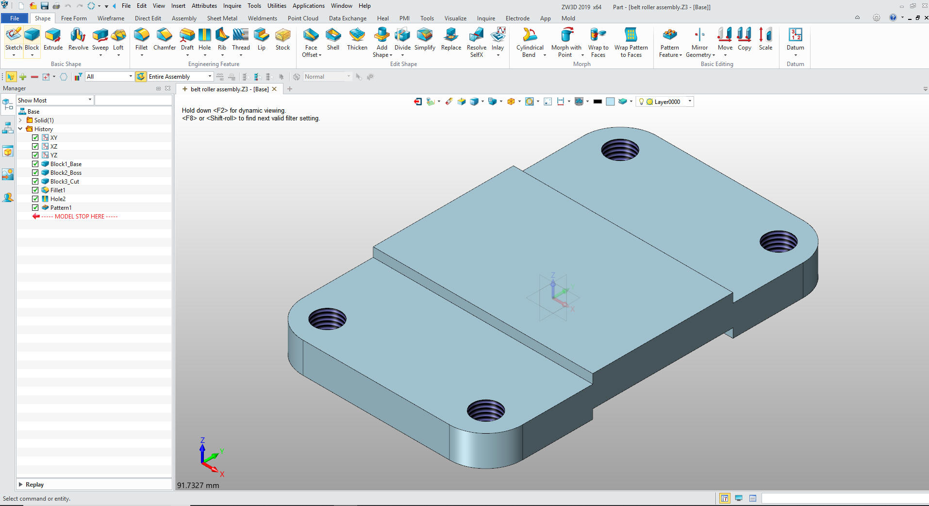
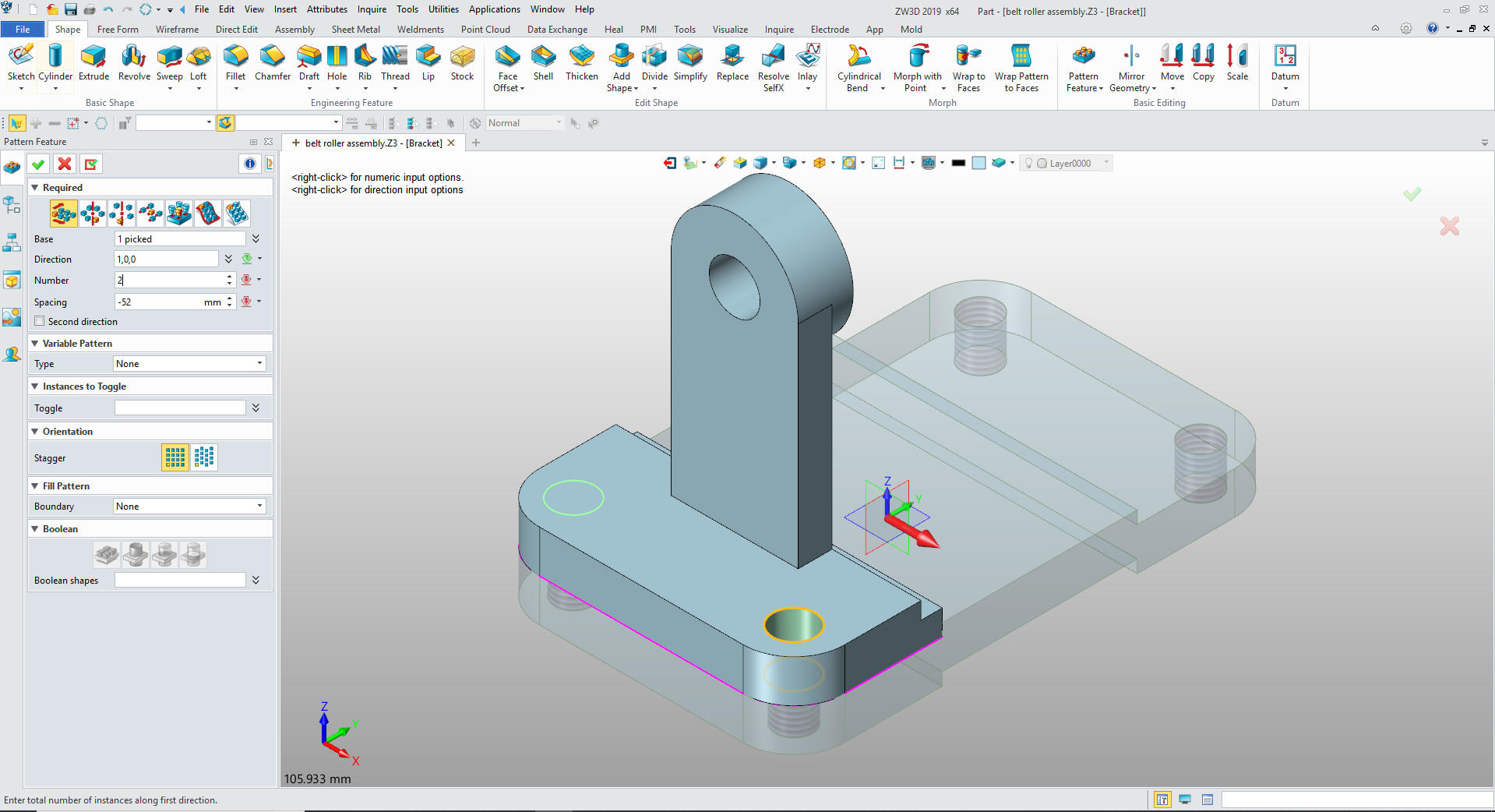
Using
the pattern feature we create the other 3 holes. I can't believe it
is as complicated to locate a hole in NX.
I select okay and we are done with the
Base.
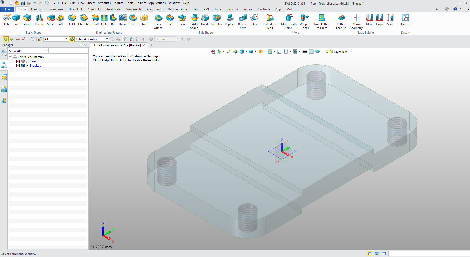
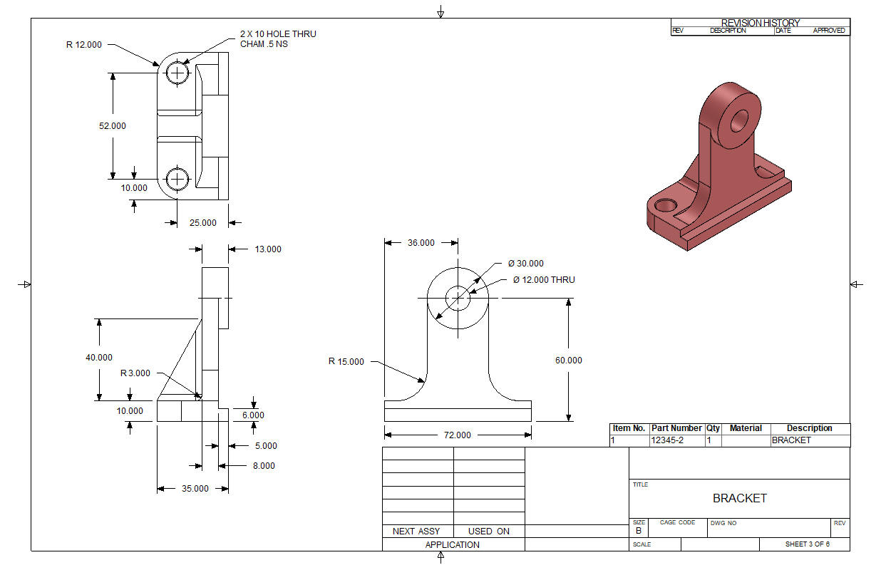
We now insert a new component called Bracket
As you can see the base is now a reference part that can be used for
in context design for the bracket.
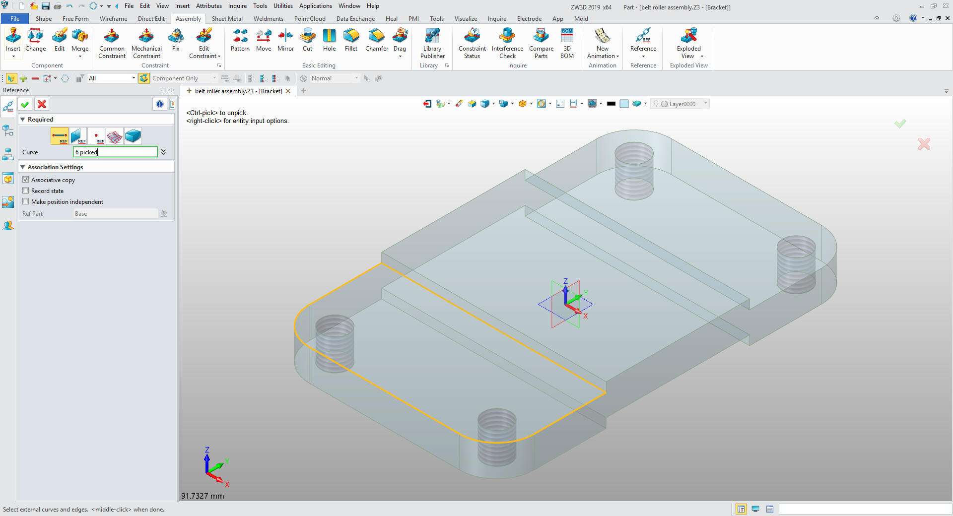
The
bracket based will be created by creating reference graphics in the
assembly tool.
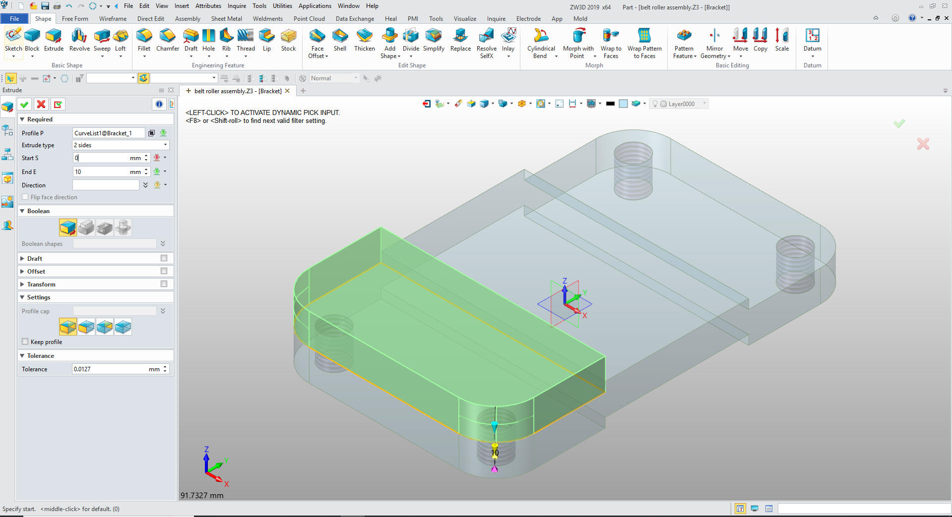
We
now turn these graphics into a curve list and extrude the shape.
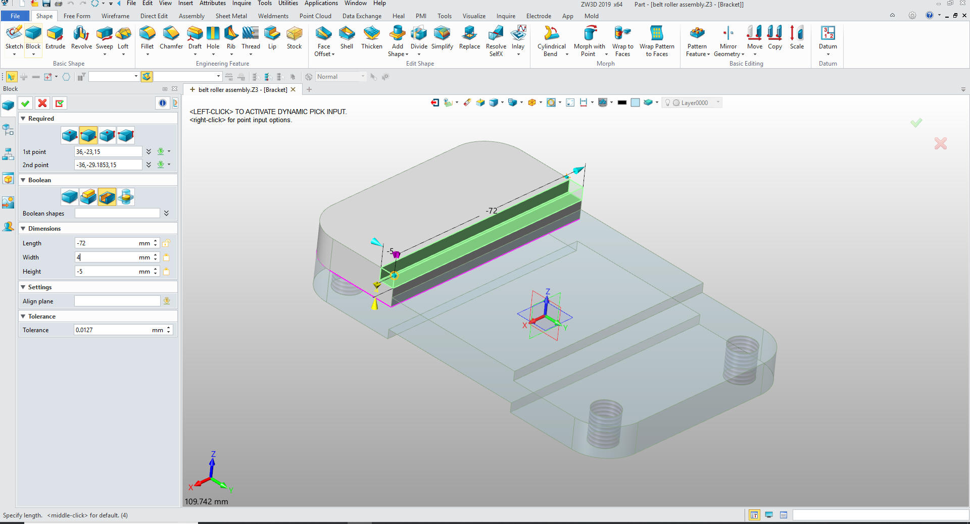
We add our cut by inserting a primitive
block locating and sizing it set it to remove.
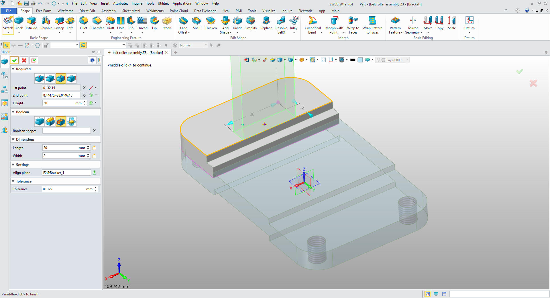
We insert another primitive block locate and size it and set to add.
Working with primitive shapes is fun. It is a short learning
curve but is so productive.
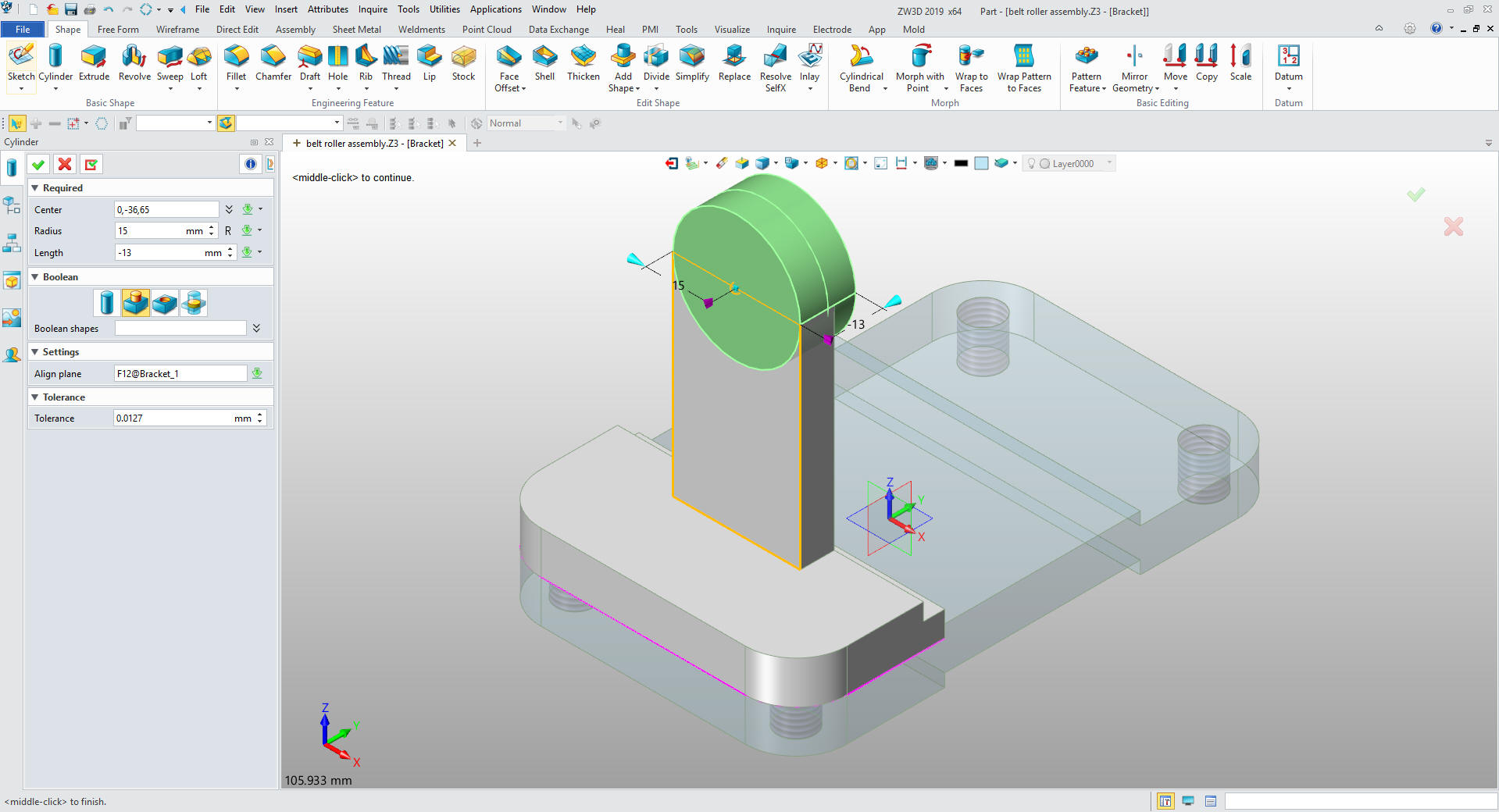
We
just insert a primitive cylinder locate and size it.
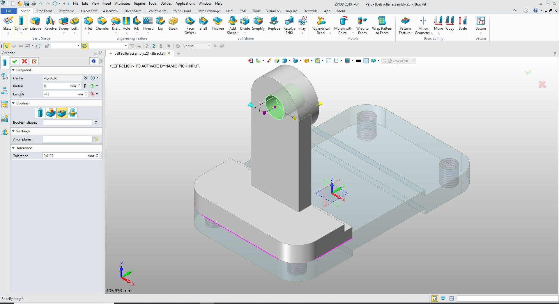
We
insert another primitive cylinder in the center of the boss, size it
and set to remove.
We
will insert a primitive cylinder, locate it and set to remove.
We pattern the hole.
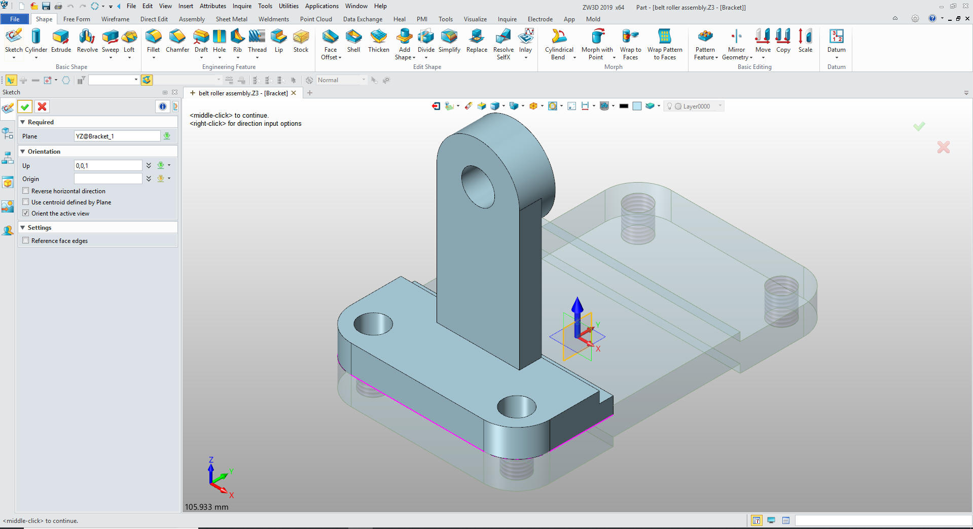
Now
for the rib we create a sketch. Yes, we do have to do some
sketching.
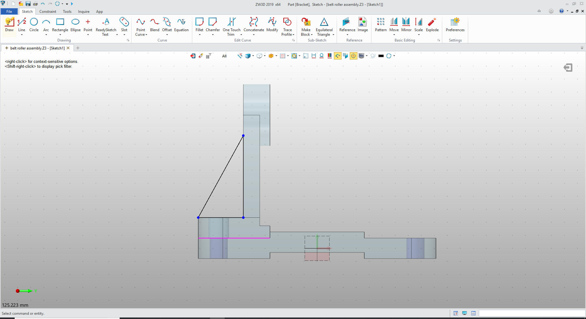
We
just use existing geometry to create the 3 lines. No constraints.
The only line we defined was the vertical that was set to 40 as we
put it in. The horizontal line was point to point.
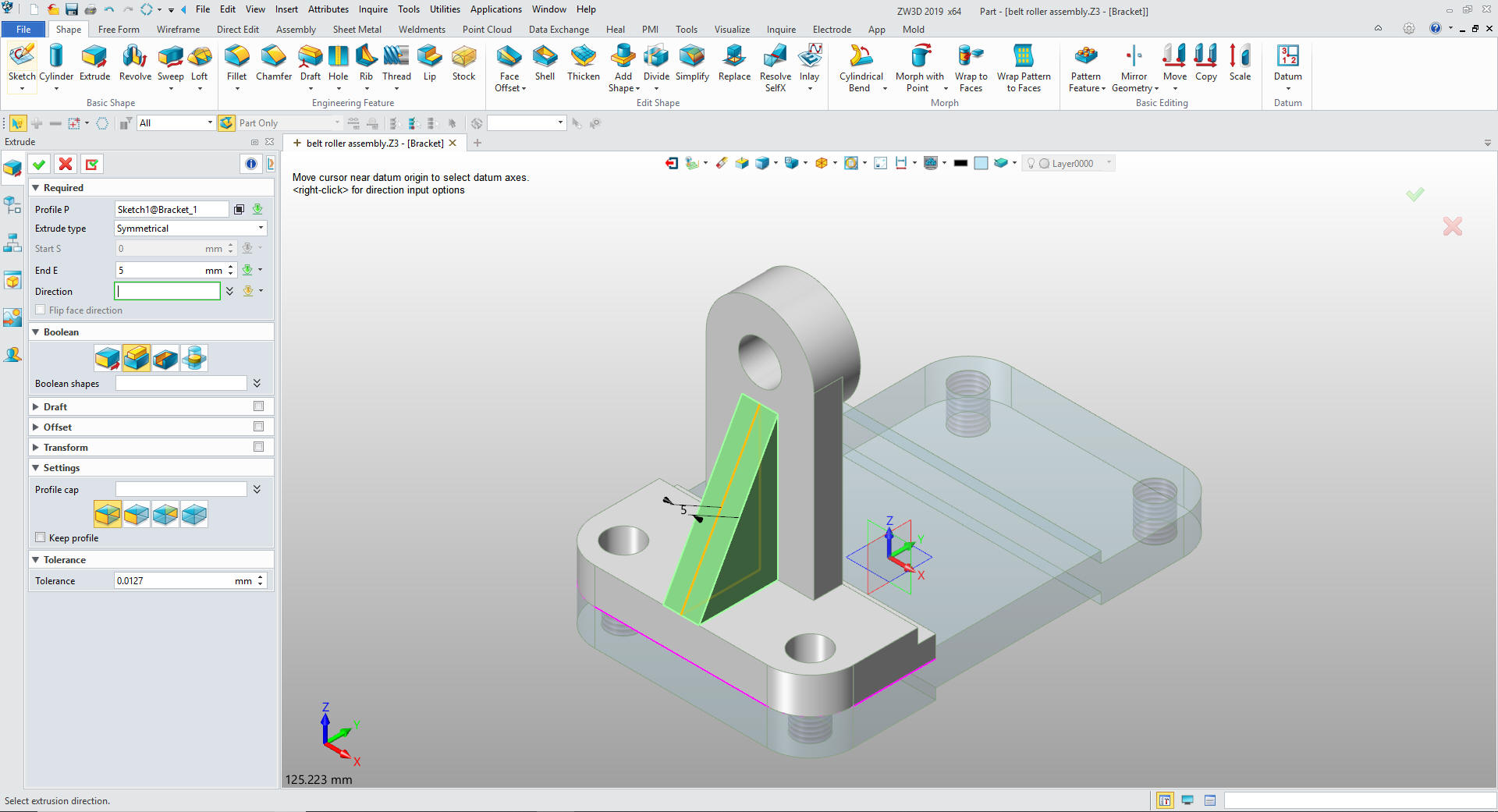
We
exit the sketch and select extrude, select symmetrical and size and
set to add.
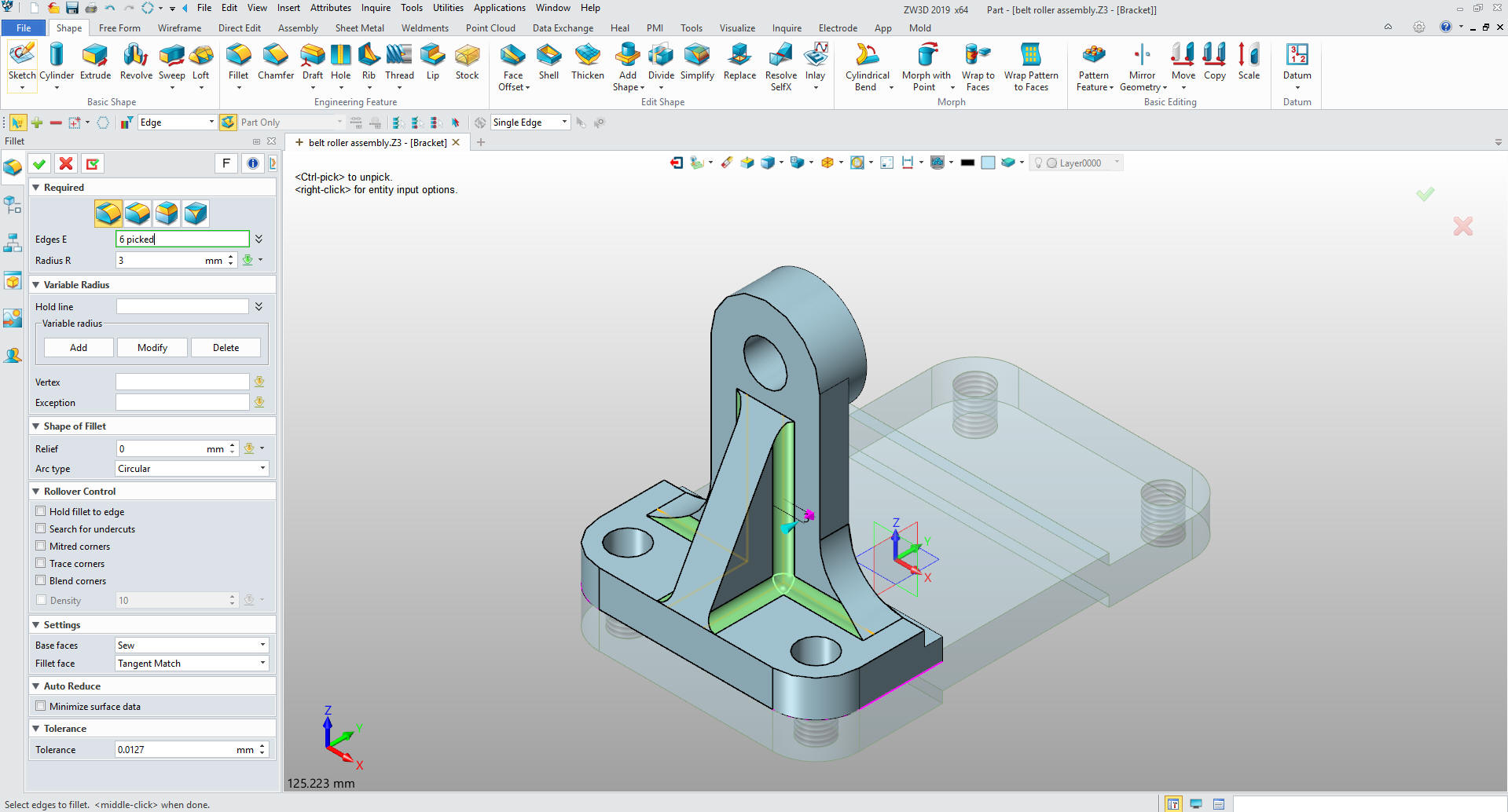
We
put in the blends and we are done.
We
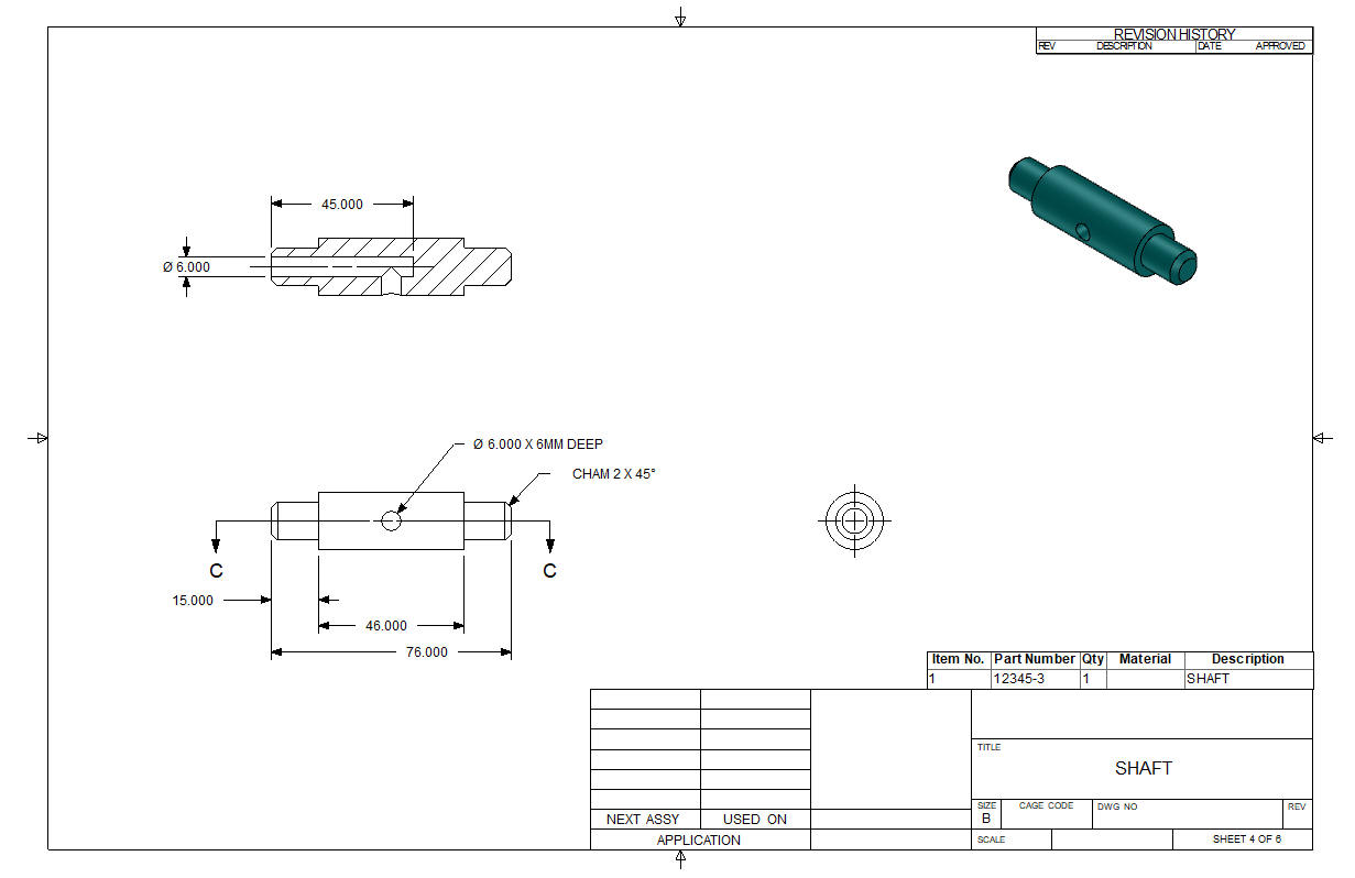
copy another bracket and locate it. We are ready for the shaft.
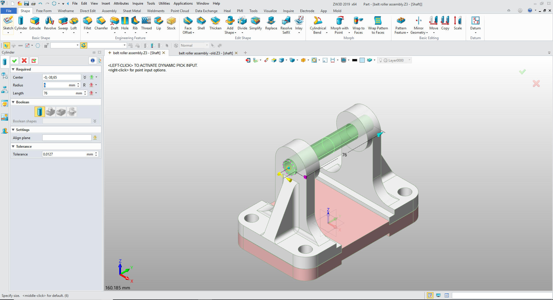
I create a reference circle and move it to the location to start
the part.
We insert a primitive cylinder using the reference
circle and a set the diameter and length.
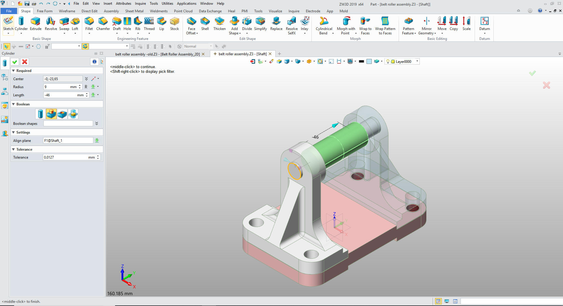
We
insert another primitive cylinder, locate set the diameter and
length.
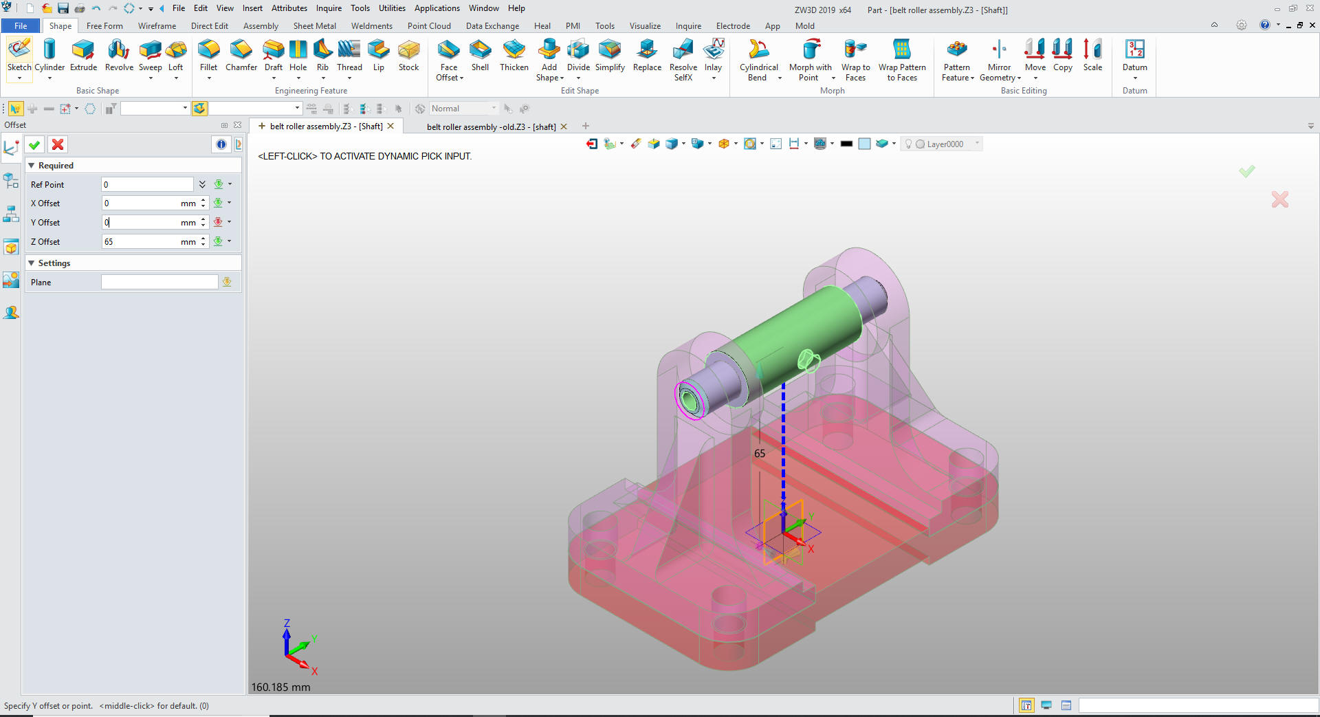
We
add the chamfers and create the hole by inserting a primitive
cylinder and setting the diameter and depth.
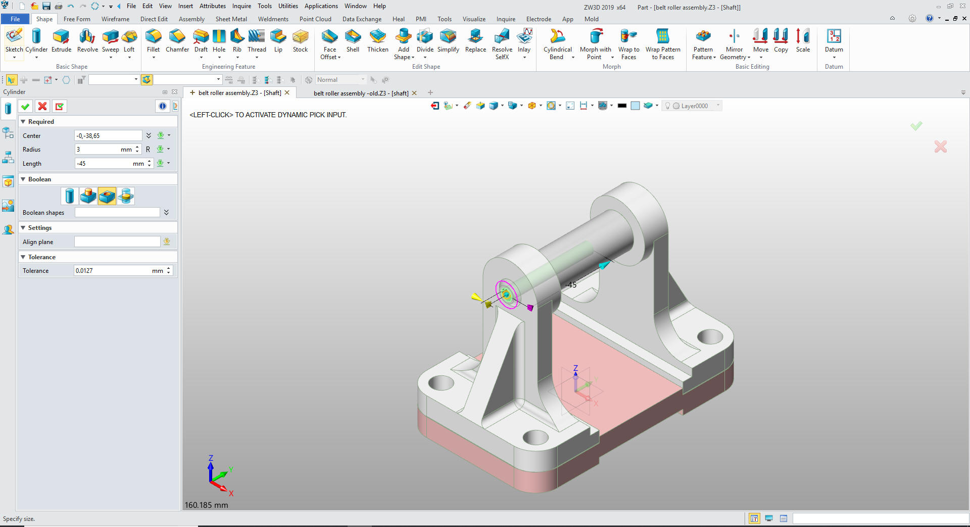
Now
for the side hole by inserting a primitive cylinder at X0Y0Z0 and
sizing and locating it. We are done with the part.
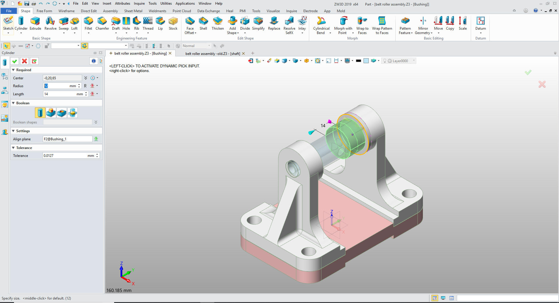
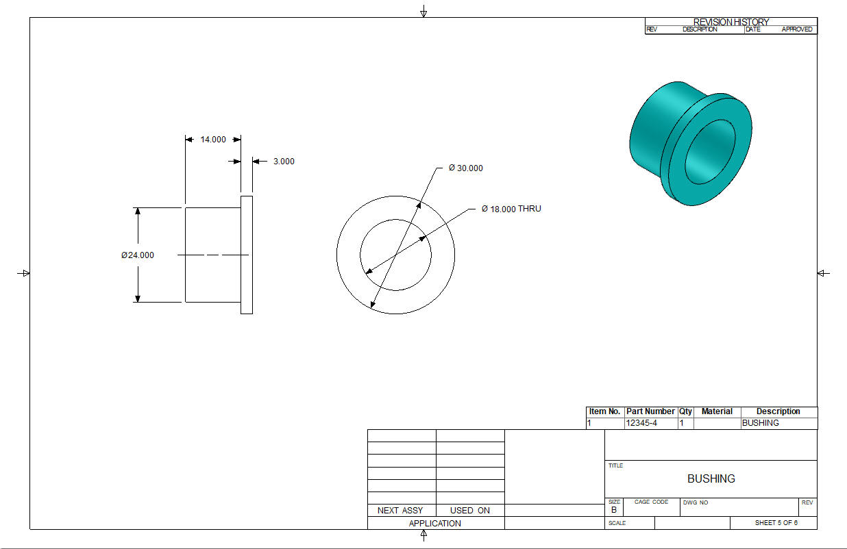
We
insert a new component and call it bushing, we create a reference
curve from the aft bracket boss and use
it for a reference to insert a cylinder, we set the diameter and
thickness,
Add
the shaft but inserting another primitive cylinder, locate and set
the diameter and length.
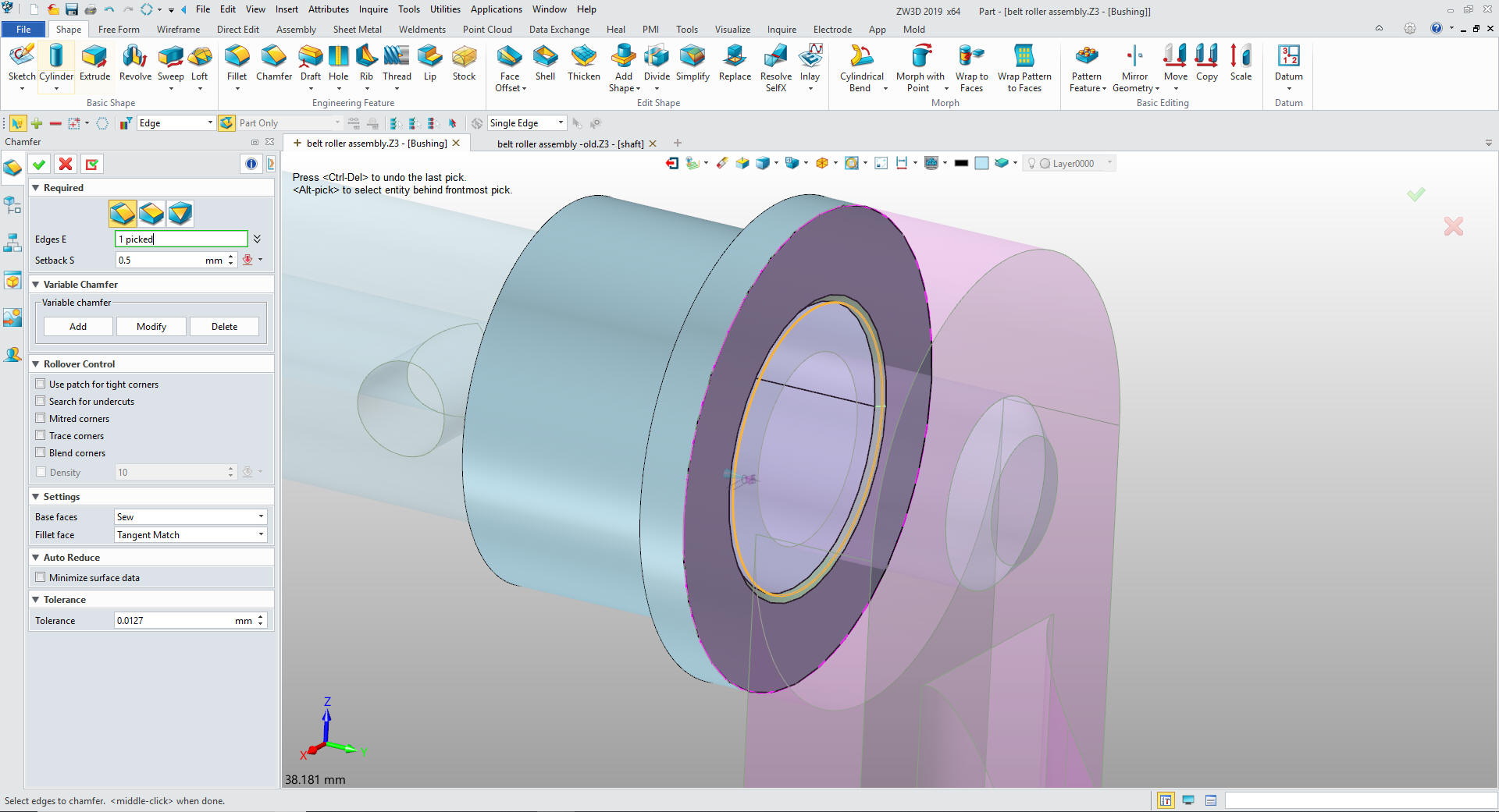
Now
for the chamfer and another primitive cylinder. I am sure all of you
have gotten the idea how this works by now
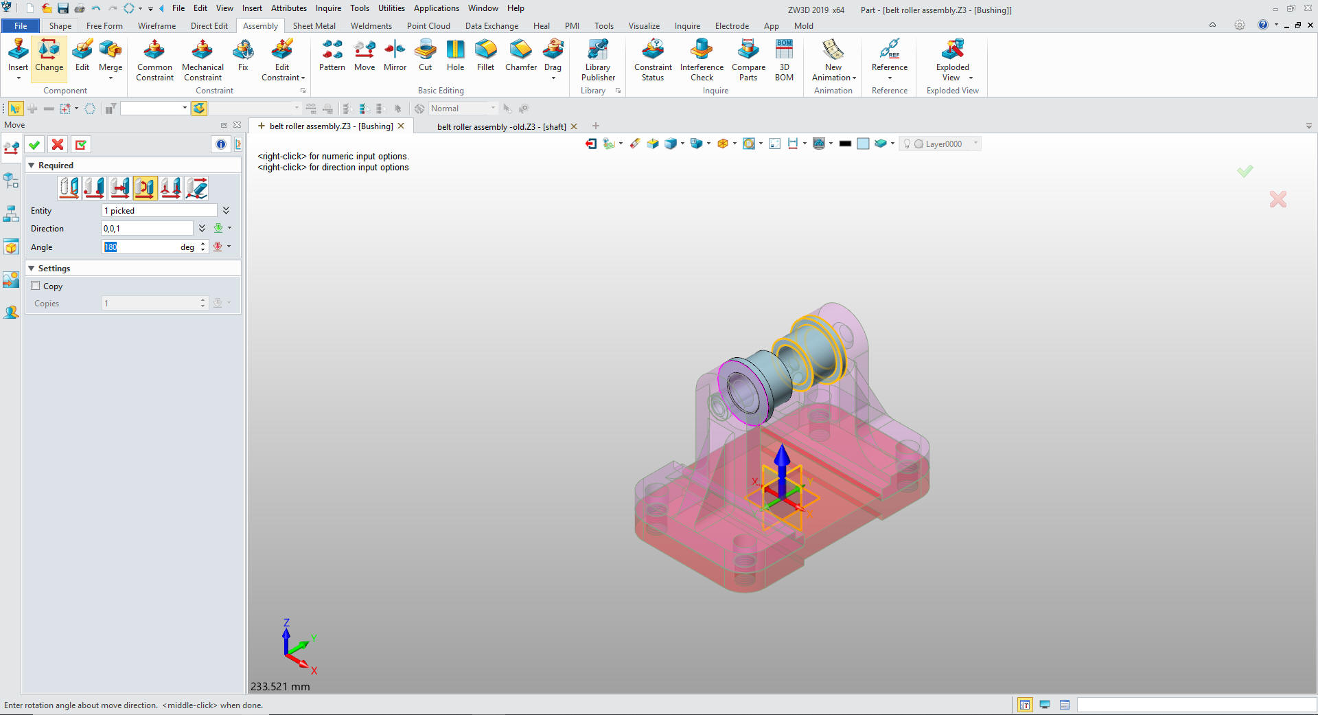
Since
there are two bushings we will copy another one and locate it.
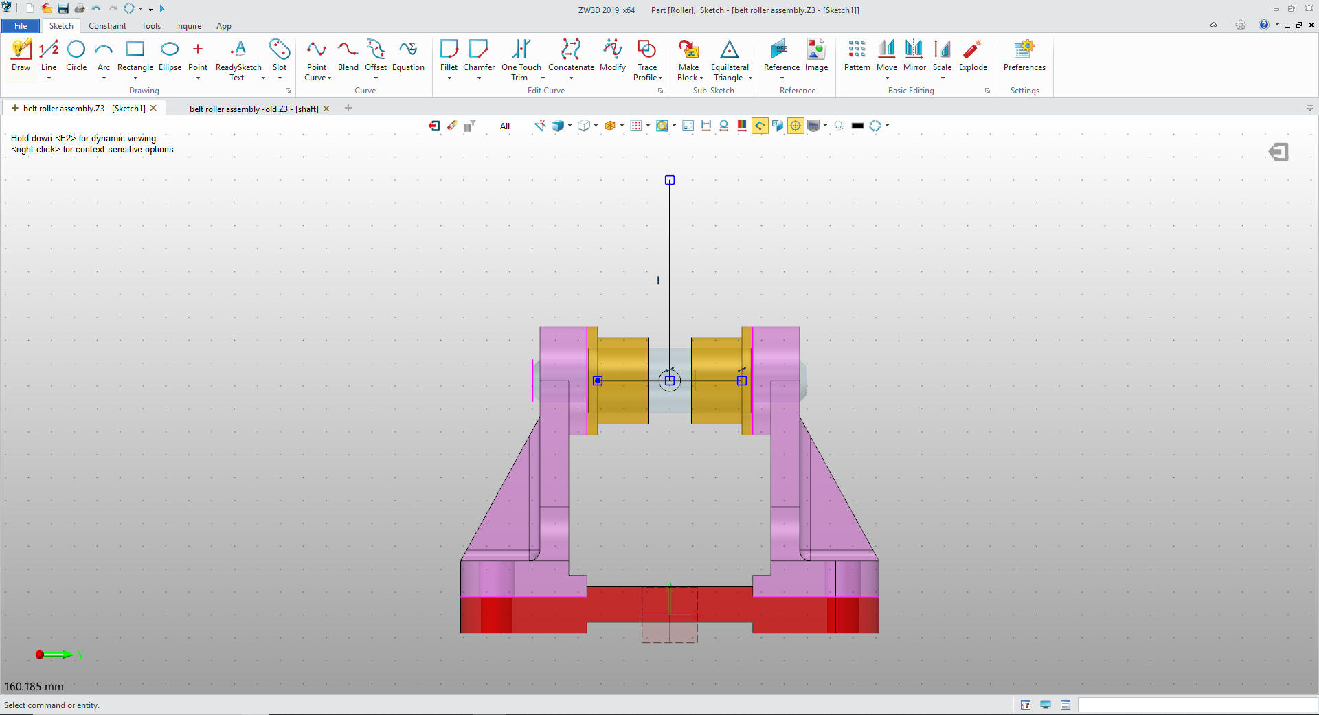
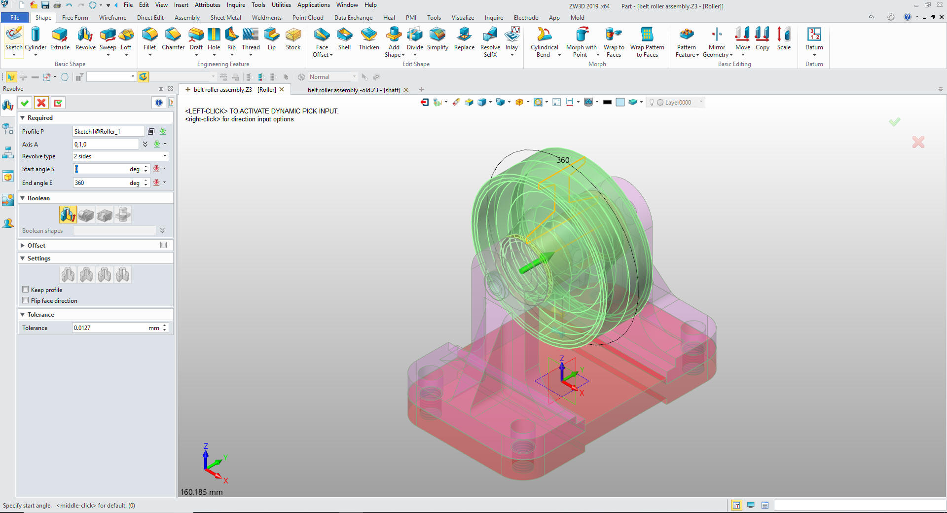
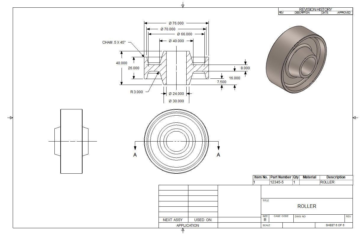
We
will add a component Roller by creating as sketch. Since I will be
using Streamlined Sketching I will create a couple of reference
lines.
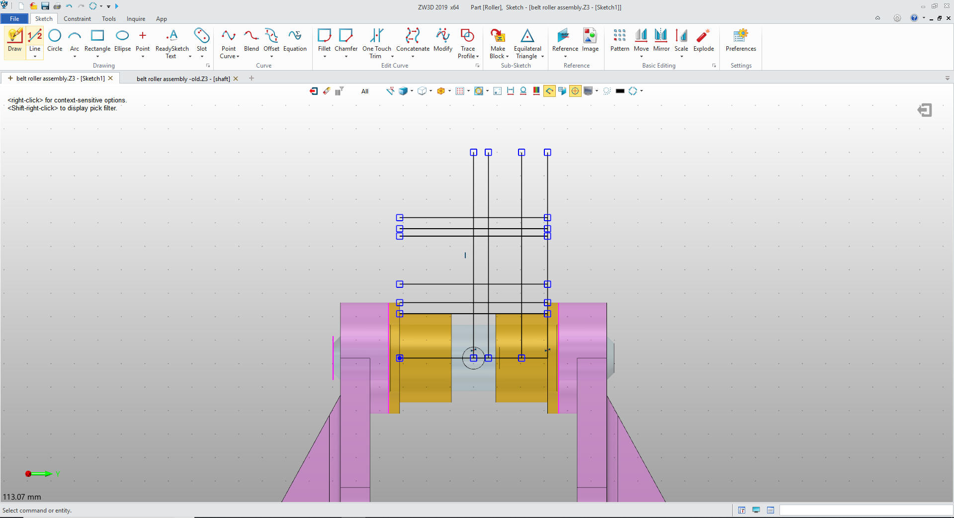
I will create my parallel offsets.
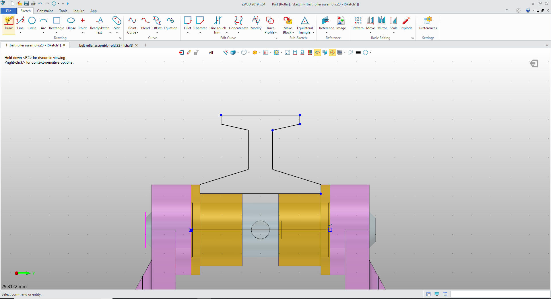
Now
create the edges of the roller by connecting the dots, trimming,
extending deleting and mirroring. Nope, no constraints.
Exit
sketch and select revolve at 360 degrees.
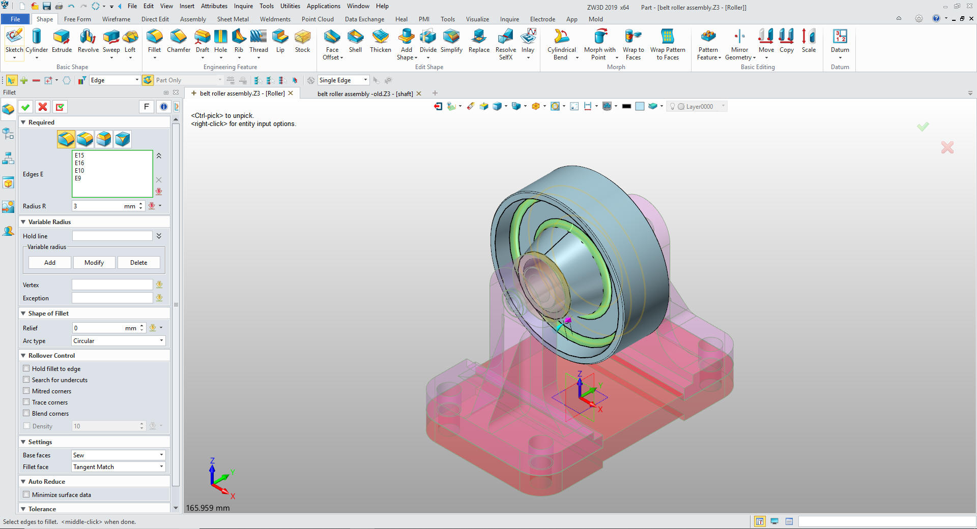
We
add the chamfers and fillets and we are done.
Now
we insert the washers and screws and pattern them and we are done.
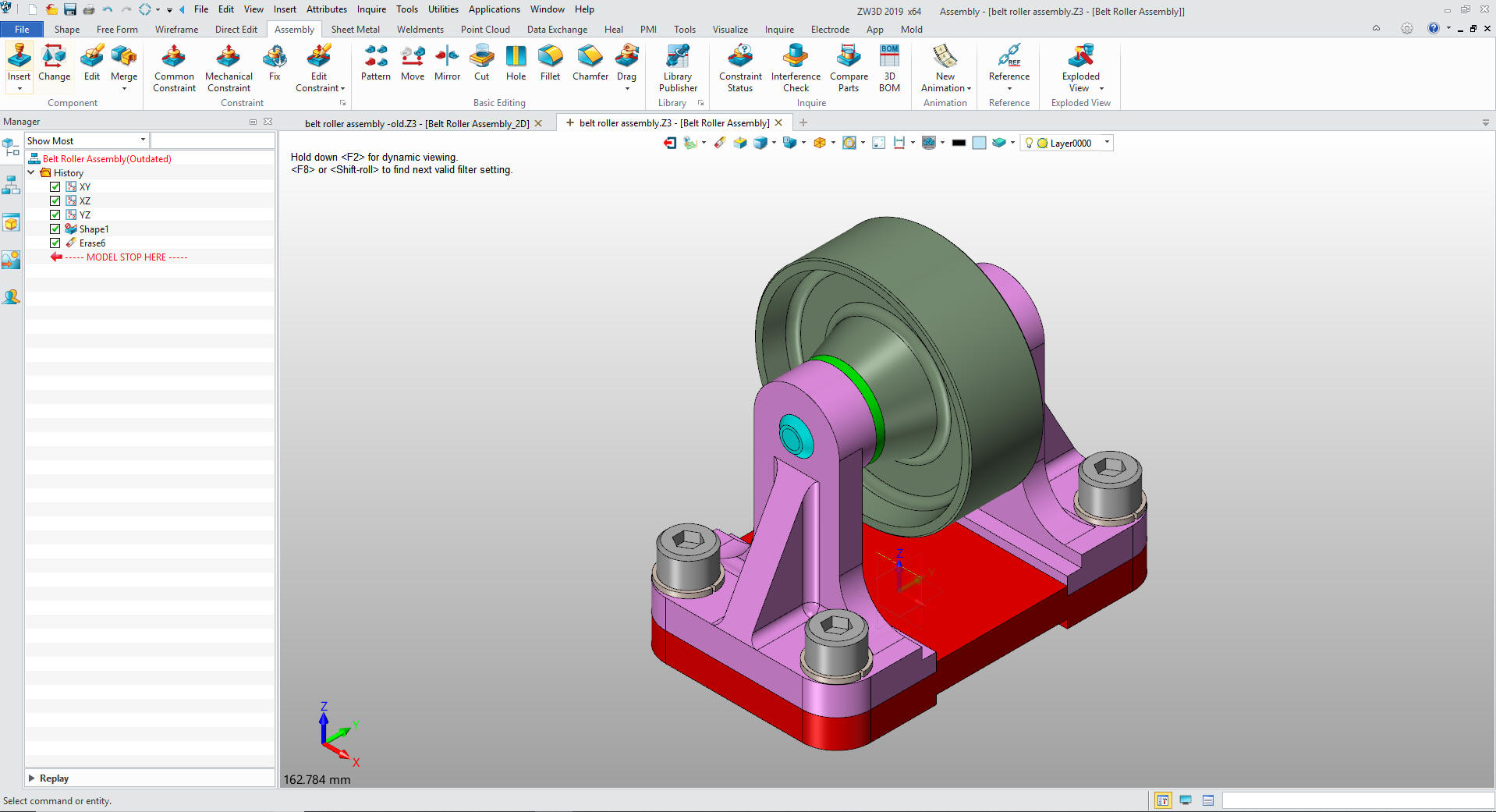
Here is the assembly.
Here are the drawings.
It is very important that you look into
how you or your engineers are creating the parts. Streamline
Sketching and Feature Based Modeling is easy to learn and implement.
It, alone, can increase productivity 10X. Now, ZW3D with its unique
history and robust direct edit functionality can increase your
productivity another 5X or more with changes! Again, time is money
in engineering.
More on Streamline Sketching and Feature Based Modeling.
To experience this increased level of
productivity, please download ZW3D for a 30 day evaluation. Legacy
data is no problem, ZW3D can read the native files of all of the
popular programs including the PMI data of NX, Solidworks, Catia and
Creo. ZW3D is a great replacement for the subscription only Autodesk
and PTC products.
Give me a call if you have any
questions. I can set up a skype or go to meeting to show this part
or answer any of your questions on the operation of ZW3D. It
truly is the Ultimate CAD/CAM System.