ZW3D vs Solidworks vs Creo Lesson One Multi-Object Environment Top Down or In-Context
Modeling
I have created
fourteen"ZW3D vs Fusion 360" lessons to show the difference between
ZW3D
and Fusion 360. It soon turned into a study in modeling techniques.
I found the Fusion 360 presenter was wasting massive amounts of time
with overly complex sketching procedures. I was so unimpressed that
I decided to model an assembly, showing my modeling techniques plus
ZW3D's superb design system.
I was quite pleased to have found these exercises from a
Solidworks dealer and thought I would show the difference in my
modeling technique plus the highly productive modeling method
offered by ZW3D. I again show modeling techniques that can easily
be streamlined even within their existing system. I call it feature
based design. Please review a few of the above ZW3D vs Fusion 360
lessons, there are more very stark differences.
I have found this tutorial Video of CREO using the same demo.
The presenter does not include the small spacer. But like the
Solidworks presenter he makes one part, this needs to be separate
parts. We train for creating functional parts not cartoons. Also the
loft process is a bit more convoluted than the Solidwork
presentation.
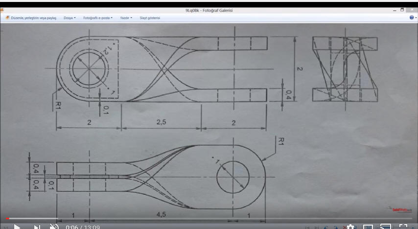
While creating 3D models from drawing is the very best
way to learn 3D CAD and maybe some design techniques it does not
expose the designer to the design flexibility necessary in design.
ZW3D is all top down due to the Multi-Object environment.
Creating mating parts is a cruise. But modeling is just one aspect of a
well designed productive 3D CAD system.
Solidworks and Creo are marginal 3D CAD systems
based on the dated Pro/e history
based modeling system. I have sold both of these products years ago and found
it, like all of the other Solidworks clones, not productive enough
for our engineering department. We use what we sell. That gives us
the experience to effectively support our user base.
I would do a
video, but I really am not good at it. So I will show you step by
step. I will try and get ZW3D support to create one. They are
very good.
The modeling technique is hugely responsible for
the level of productivity. Those of you that are only trained in the
sketch, sketch, constrain, constrain world are truly limited by not
using the freedom of Streamlined Sketching and Feature Based
Modeling that is available in even the most Solidworks-ish of CAD
systems. If your designers are designing in these very unproductive
and time-consuming processes it might be time to review your
standard design procedures. Don't have any do you?
These
lessons have turned into exercises in modeling techniques as
compared to showing a more productive CAD system. Again, I say,
there are many ways to model a part. I see with my exposure to
direct edit modelers like CADKEY, I rarely sketch like you see the
Solidworks fellow doing. I have always created my basic sketches by
mostly creating offsets and extending and trimming. I call this
Streamlined Sketching. It seems to be much easier. I never put in a
fillet that can be created later. What do you think?
Let's get started!
We are already in
Inches. So we can start modeling.
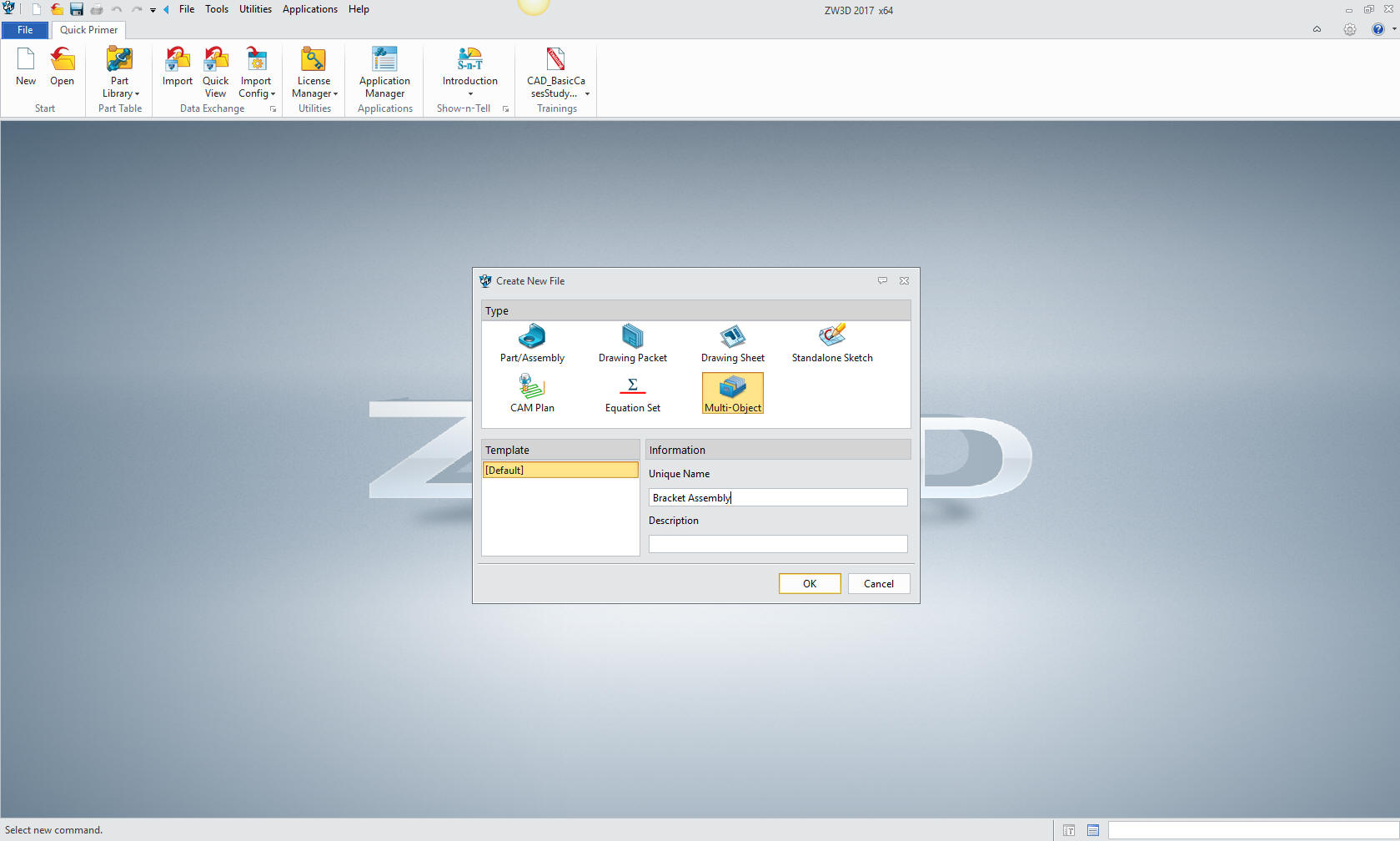
This is an inseparable
assembly not a part. So we will create a new multi-object file. This
is one of the functions that make ZW3D much more productive.
Offering the ability to have your project including all of your
parts and sub-assemblies in one file. PDM would not even be a
problem. Plus the drawing is also integrated.
We will
create the top assembly and name it Bracket Assembly
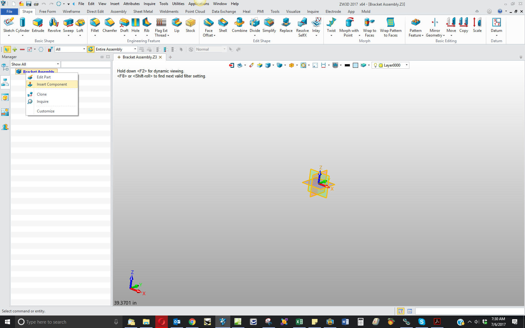
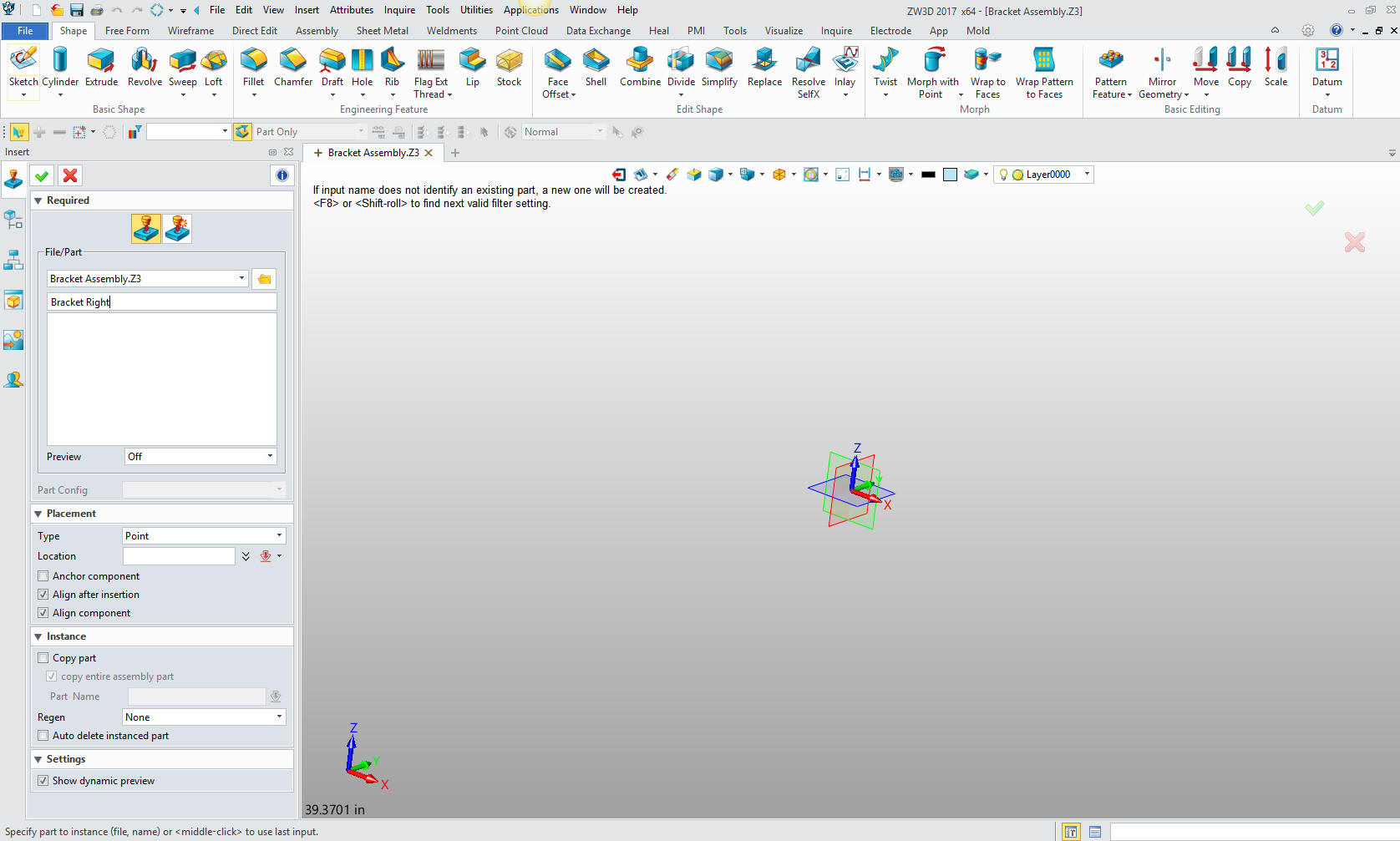
Now we
insert the first component, the Bracket Right. I am showing
you these step to present how we set things up in the multi-object
environment. There are a few Solidworks clones that offer a
environment like this but it is basically an after thought and not
an integrated part of the
basic program.
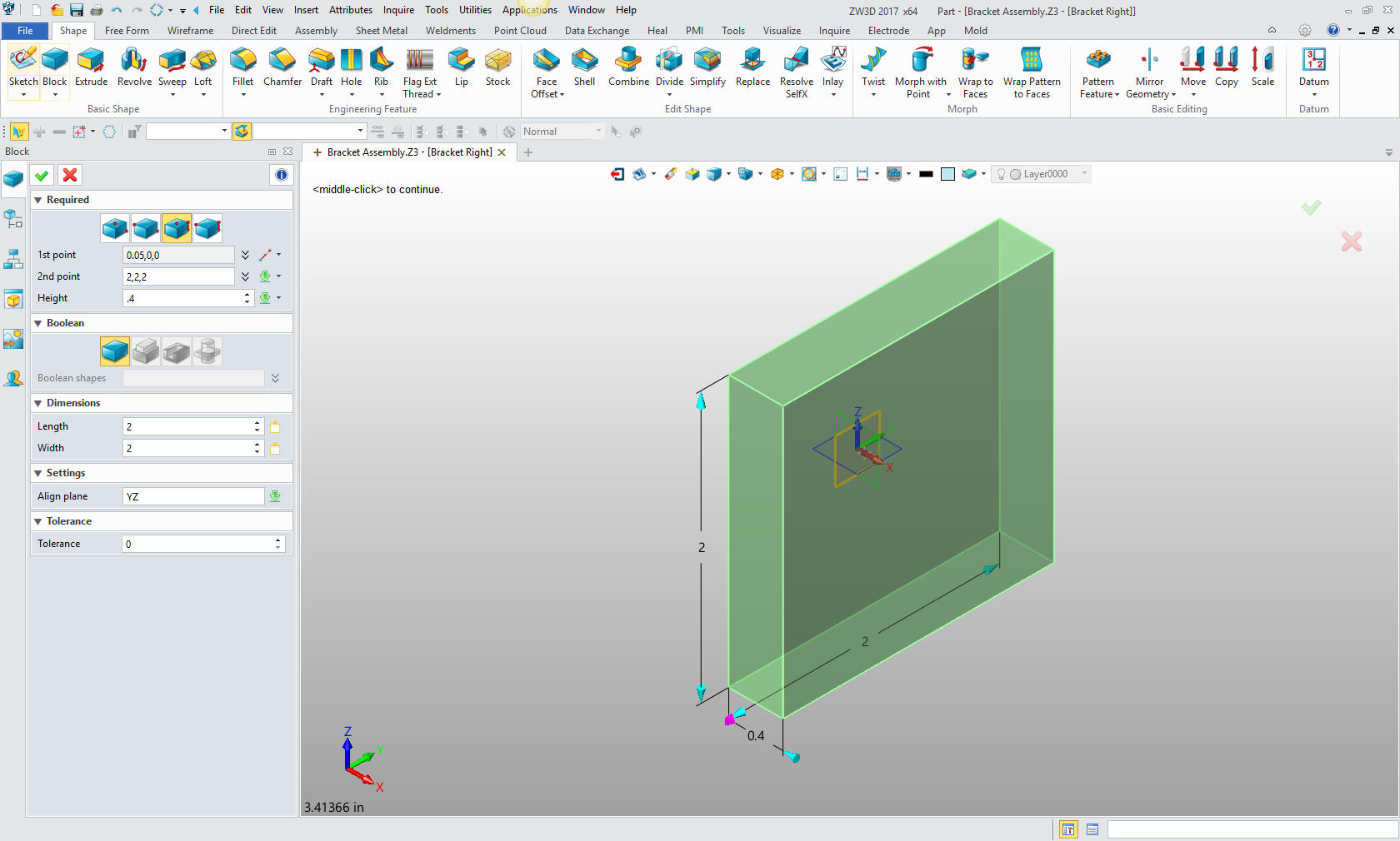
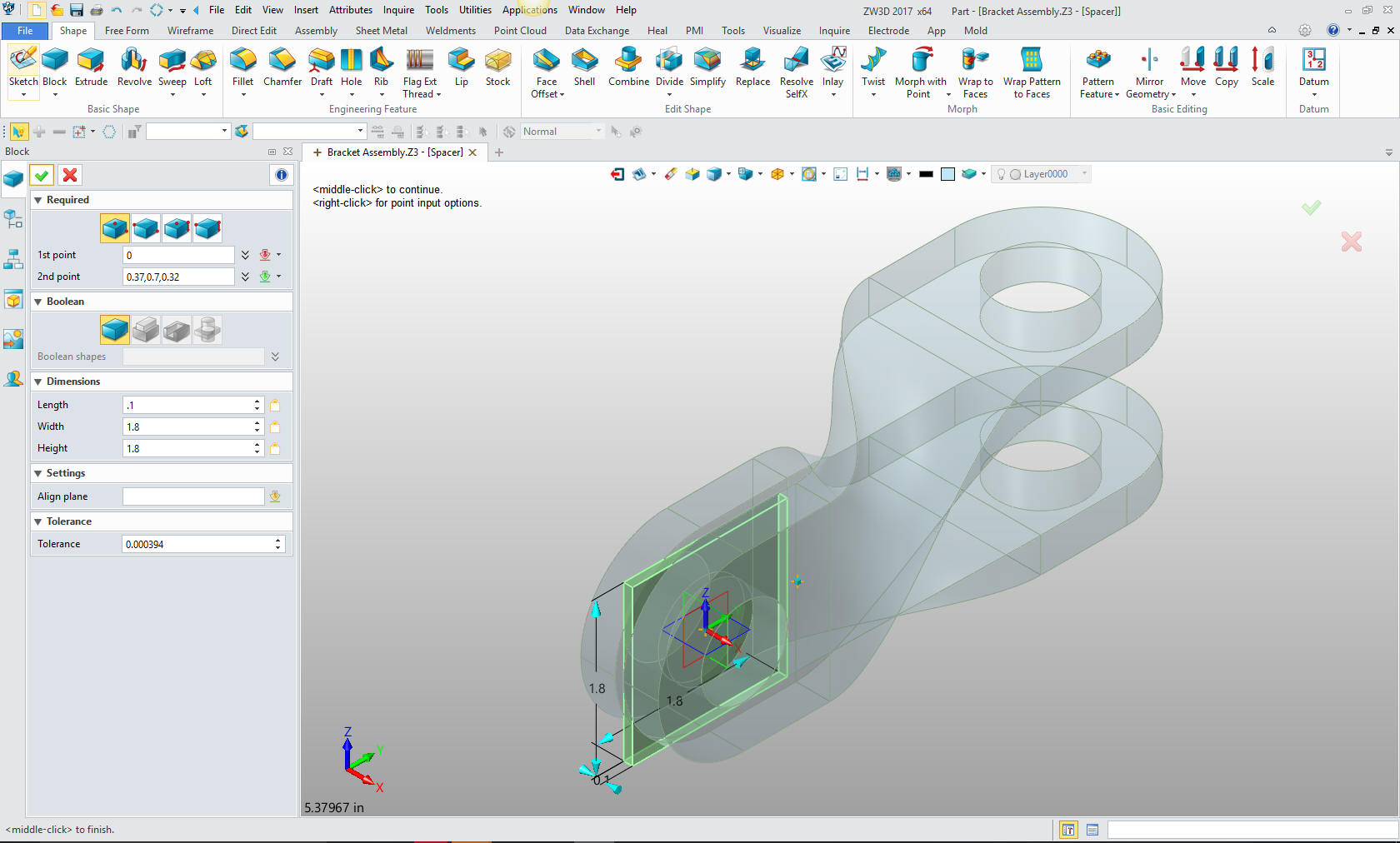
We can now start designing. We insert
a block at X0Y0ZO, offsetting it .05 and size it.
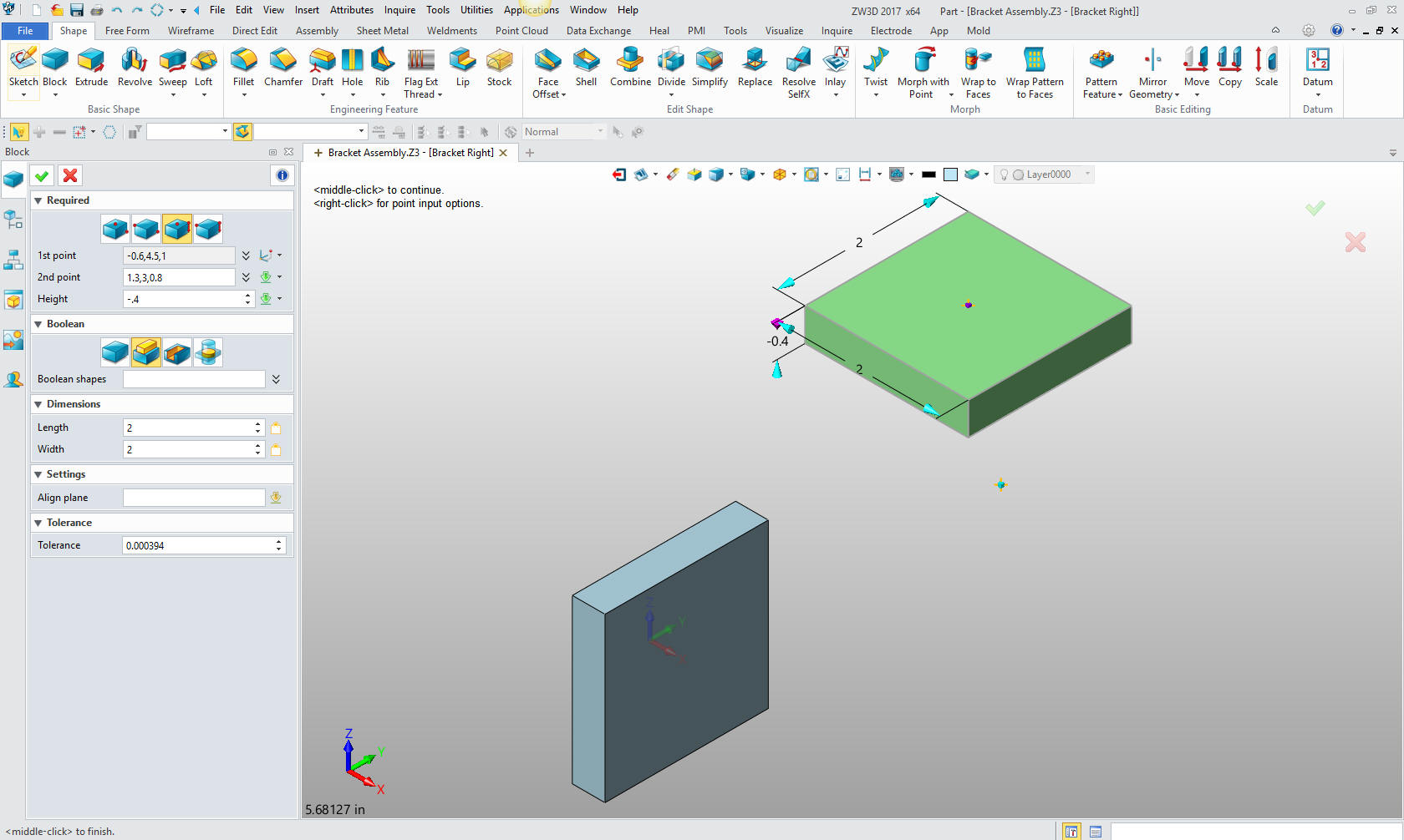
We
insert another block, locate and size it. I used primitive blocks to show
an alternative to sketching. You have the option to use either
function, as you get experienced you can decide which is more
productive. For me "Feature Based Design" is very easy and usually
my first choice.
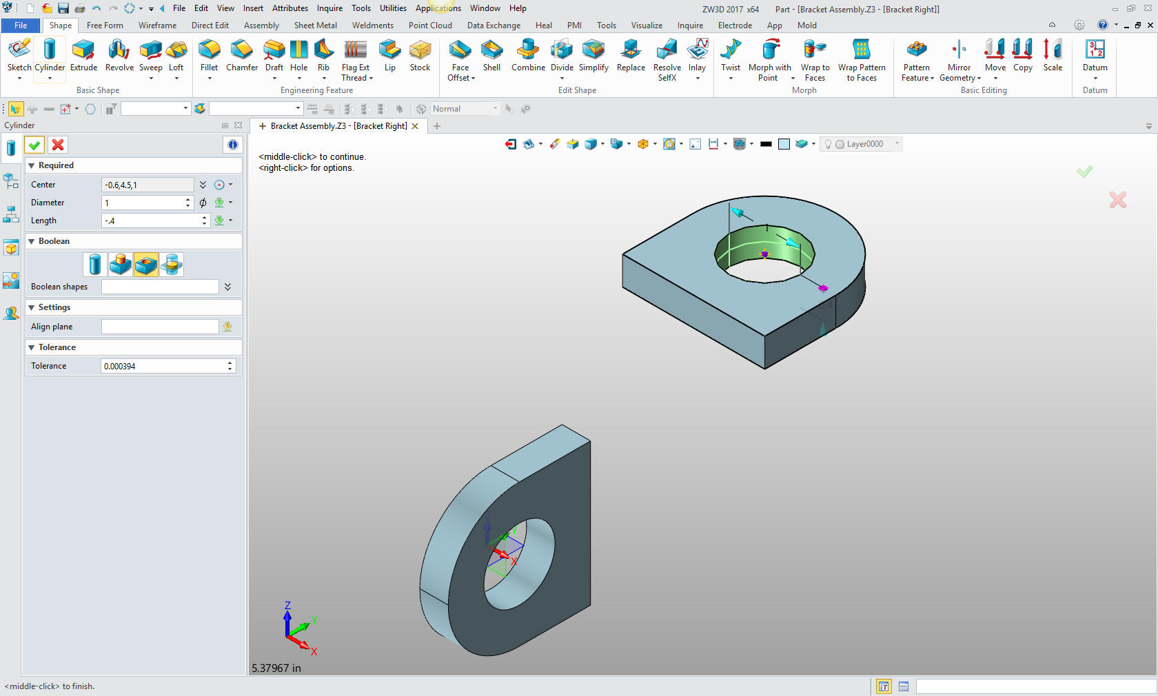
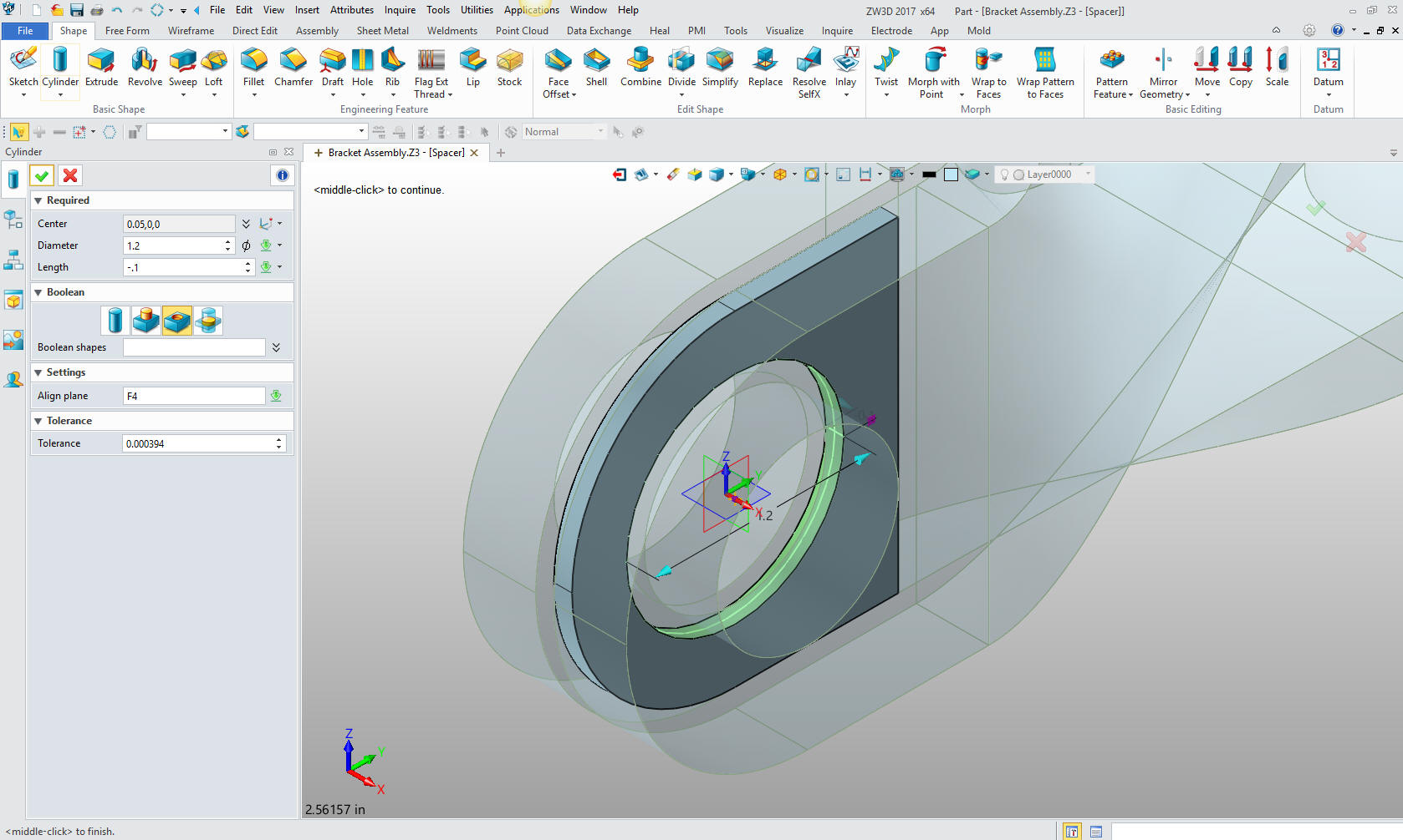
We will add the fillets and hole. I could have just as easily copied
the first block.
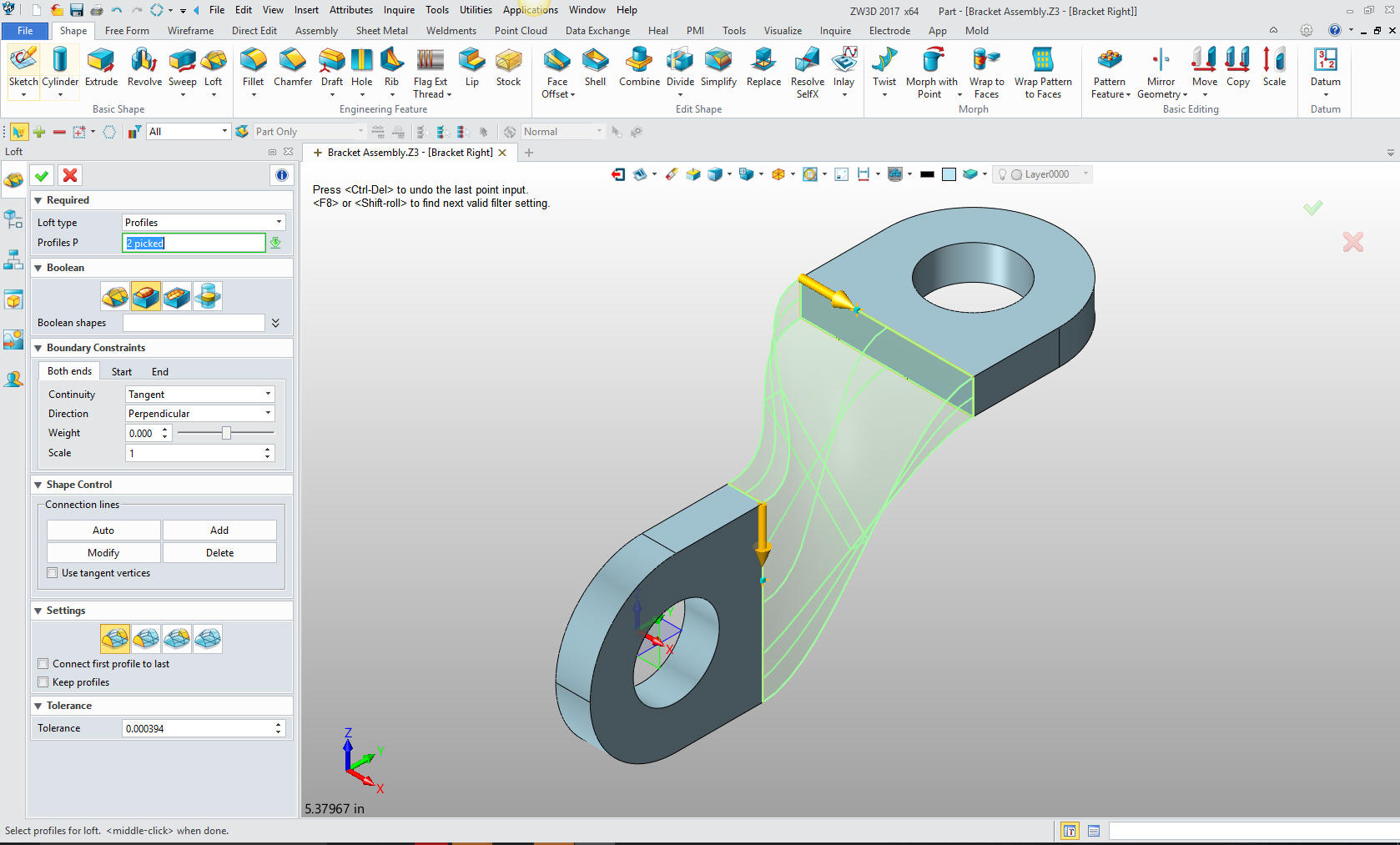
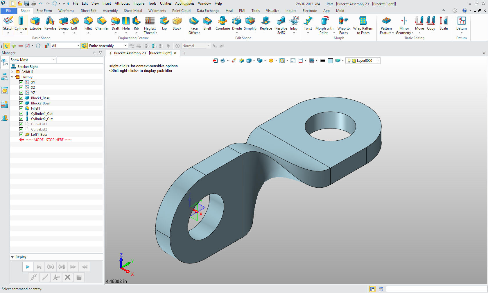
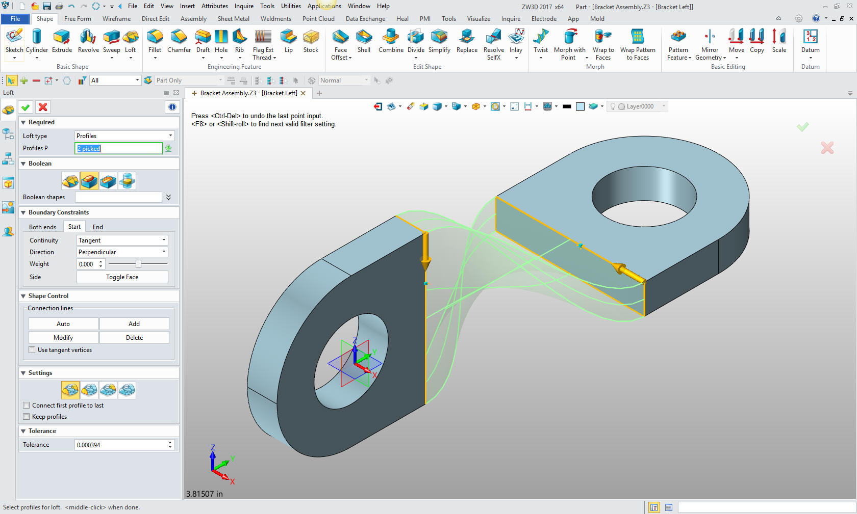
Now for the twist. This is a great
command. We need profile curves to generate the loft and creating a
curve list is an option in the command. So it is quite easy.
We are done with the first bracket
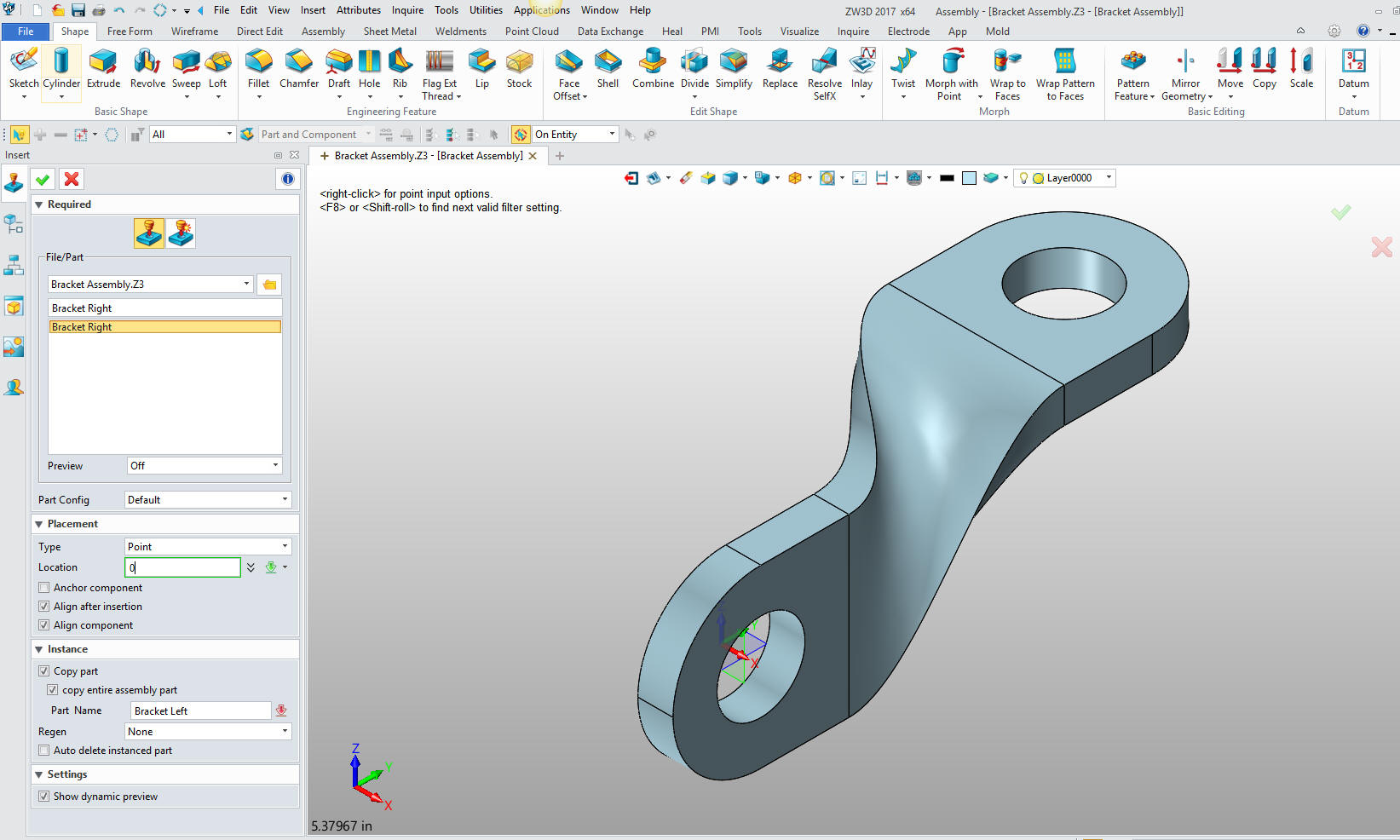
We will now create a new component. We will just copy the first
bracket and name it Bracket Left and locate it at X0Y0Z0.
We open Bracket Left and start to work. We first delete the twist.
There is more to this assembly than meets the eye.
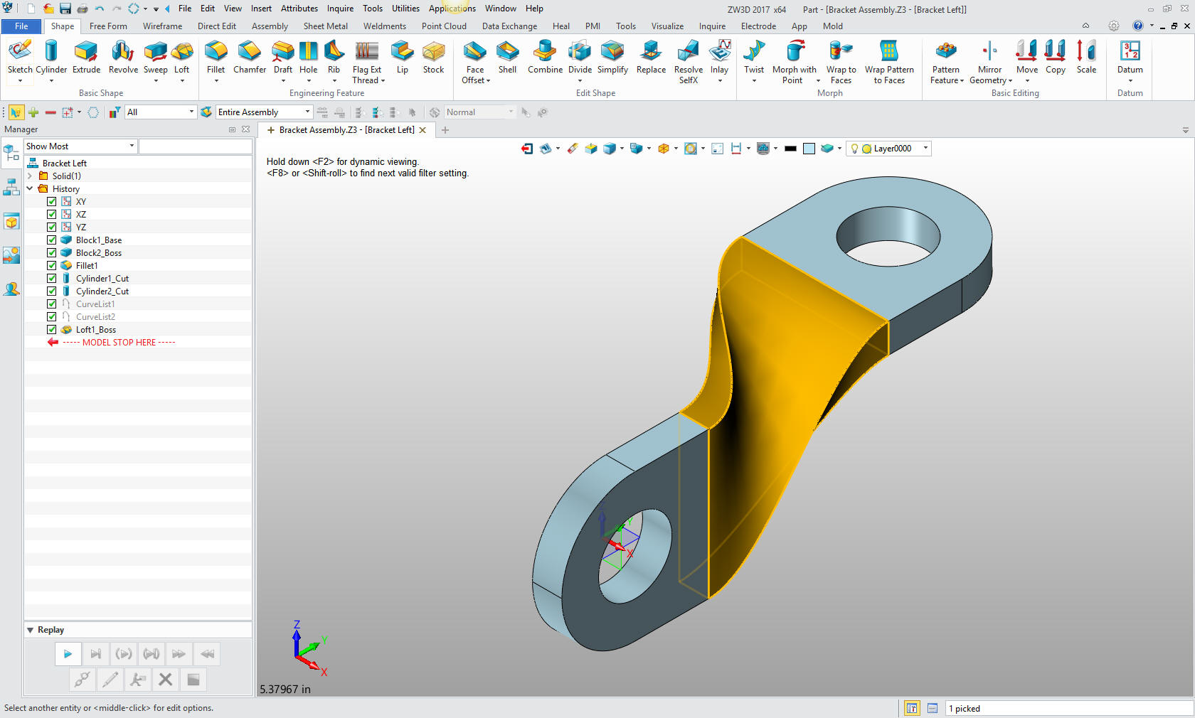
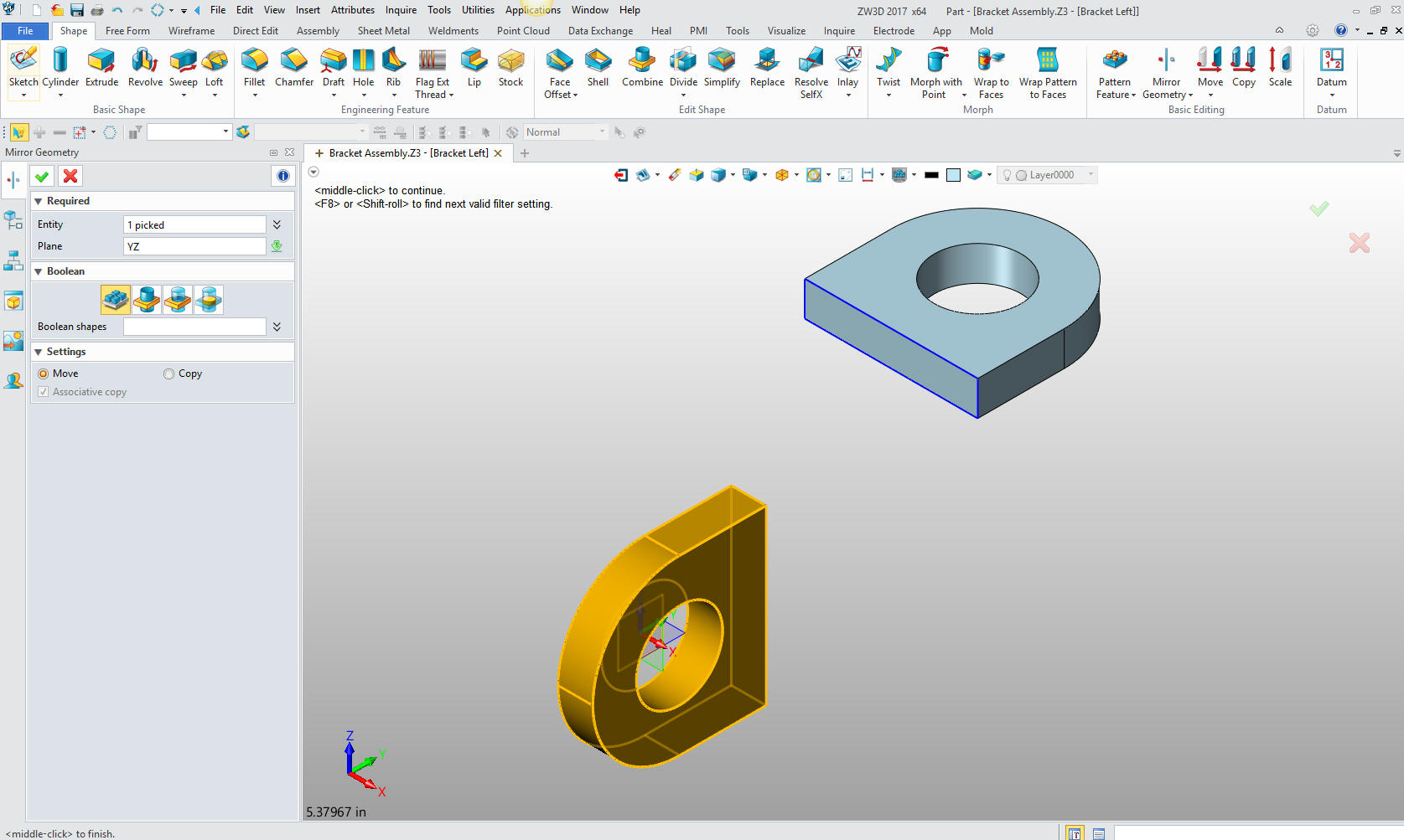
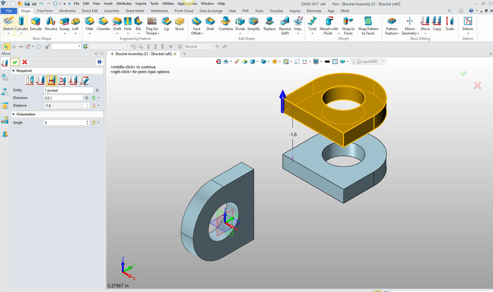
Now we
mirror move the vertical end using the YZ plane. This is the reason
I offset the first block.
We
move the horizontal end into place.
We are
now ready to add our twist.
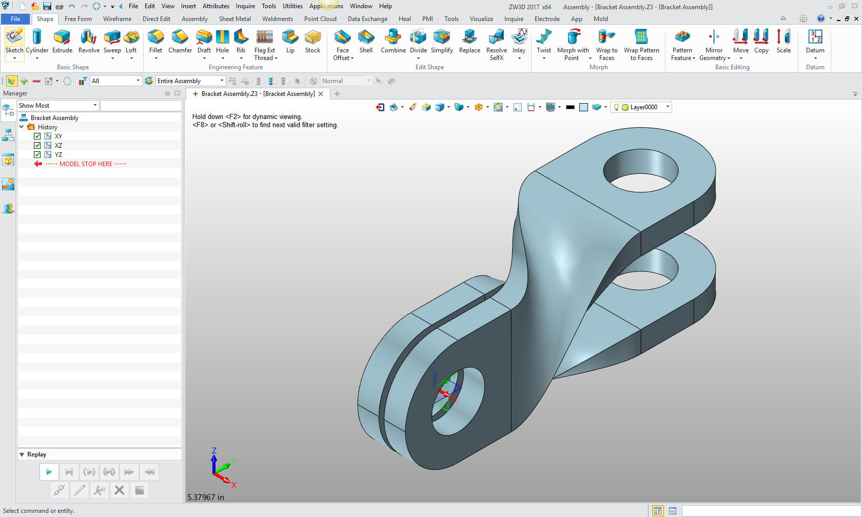
We are
now done with our two brackets.
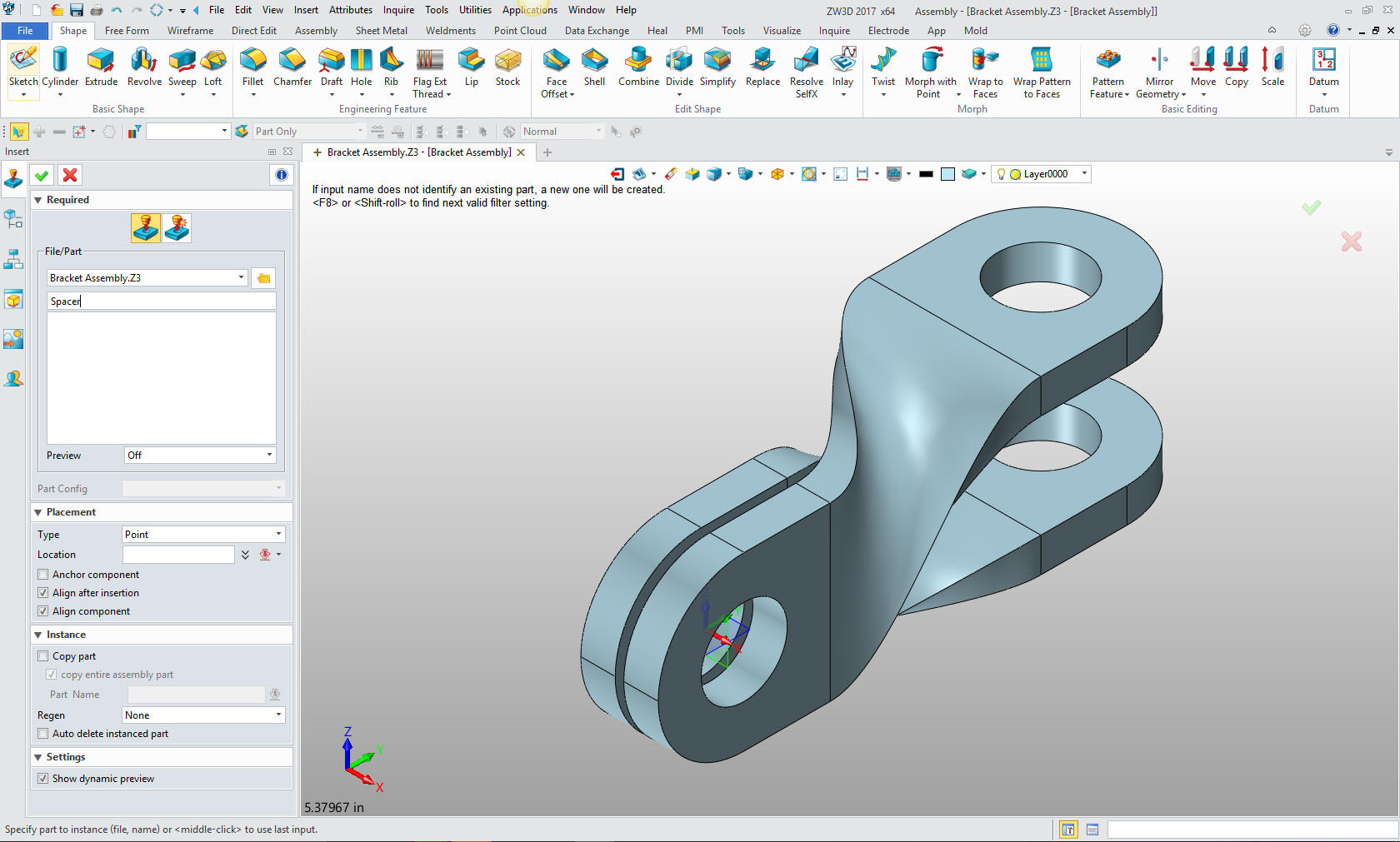
Now for
the spacer. We create a new component under Bracket Assembly.
We just leave it in edit mode and insert a block at X0Y0Z0.
We
put in the fillets and hole and we are done with the assembly.
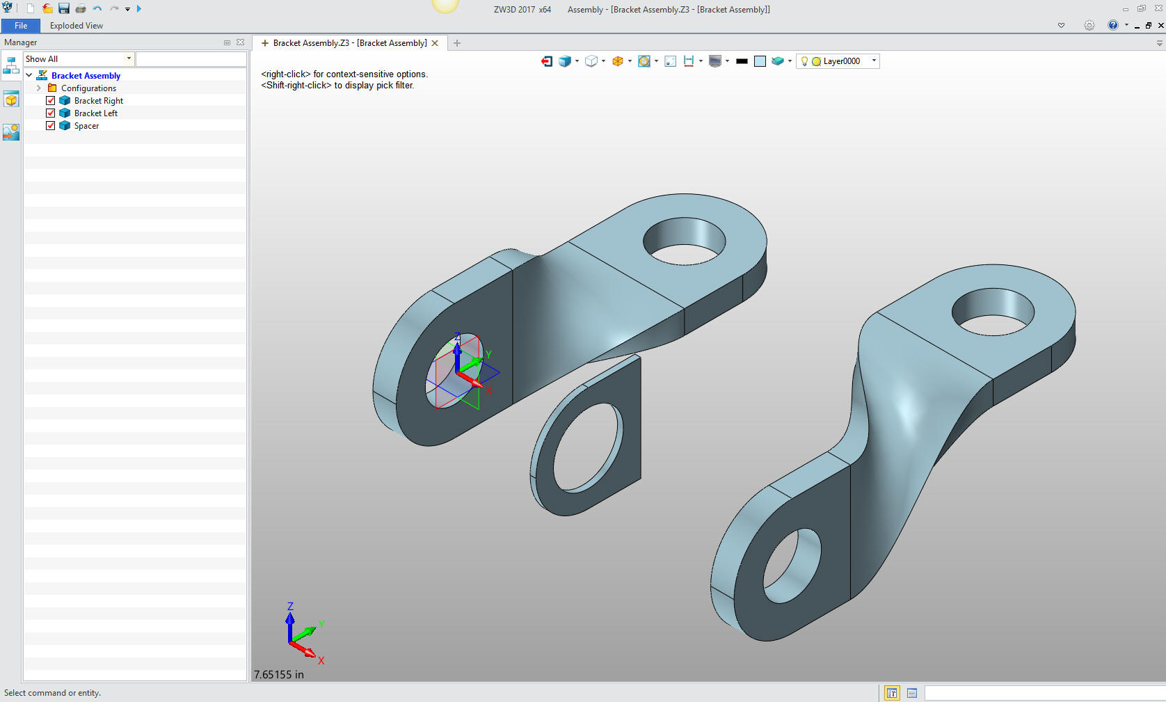
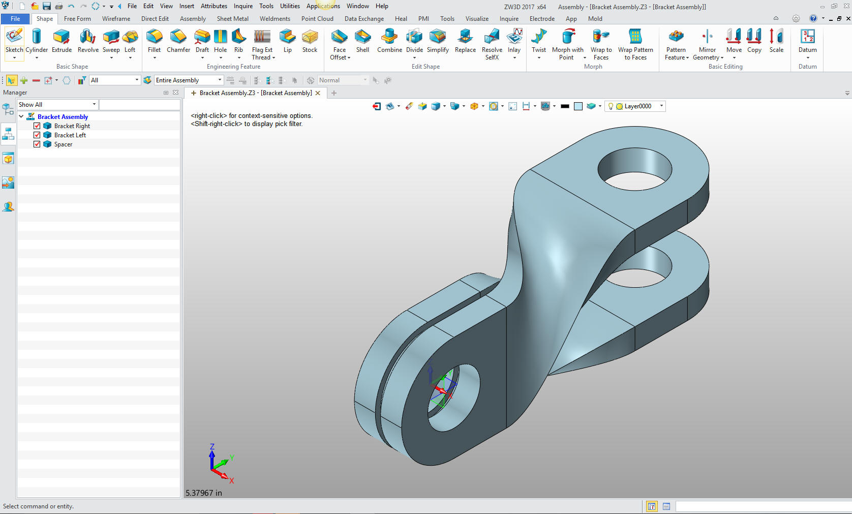
Here is the final assembly. You can see how easy it is to design an
assembly in one
file.
Here
is an exploded view.
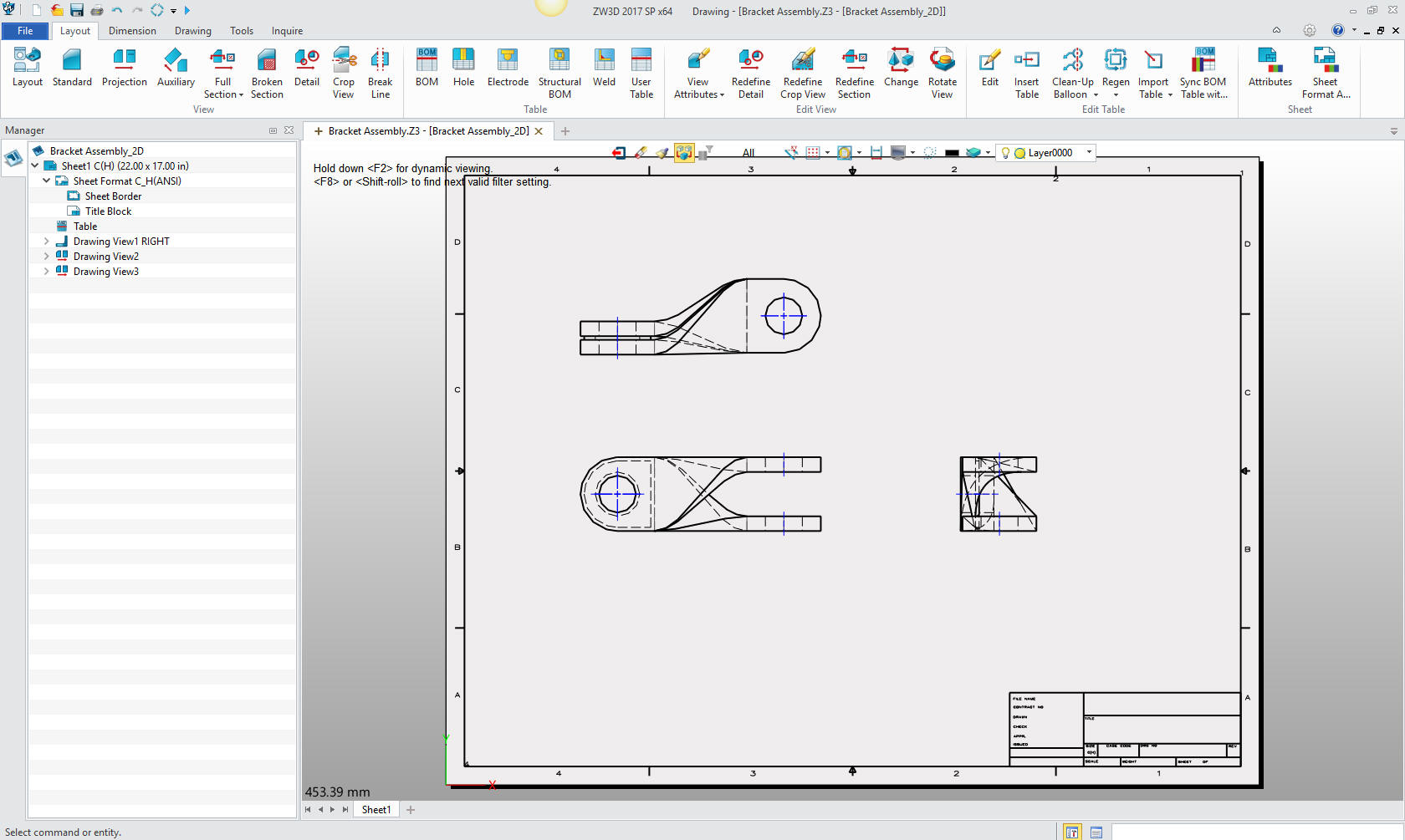
We
select 2D sheet and create the associated information document
(drawing) This is integrated in the same assembly file. Imagine
how having this feature could simplify your PDM?
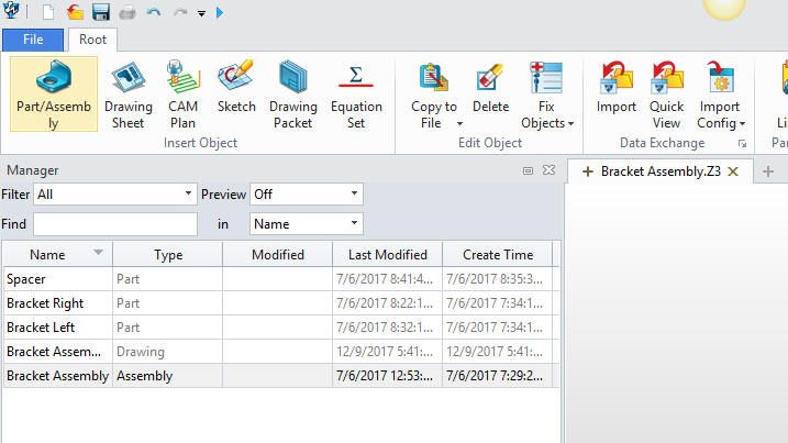
You
can see the drawing included with the other parts or subassemblies
in the Object Manager.
Give me a call if you have any
questions. I can set up a skype or go to meeting to show this part
or answer any of your questions on the operation of ZW3D. It
truly is the Ultimate CAD/CAM System.
If you are interested in adding professional
hybrid modeling capabilities or looking for a new solution to
increase your productivity, take some time to download a fully
functional 30 day evaluation and play with these packages. Feel free
to give me a call if you have any questions or would like an on-line
presentation.