3D Modeling Techniques
ZW3D vs Solidworks Lesson Thirteen Primitive
Shape Design Streamlined Sketching/Feature Based Modeling
Modeling note:
It is funny,
you may not realize how you model because you have many ingrained
processes from the past. I have been doing Boolean (direct edit)
design since the beginning of solid modeling in CAD. As I have been doing these comparisons I
realized that I design in shapes. ZW3D has primitive shapes and
robust direct edit functionality. I look at the drawing and pick out
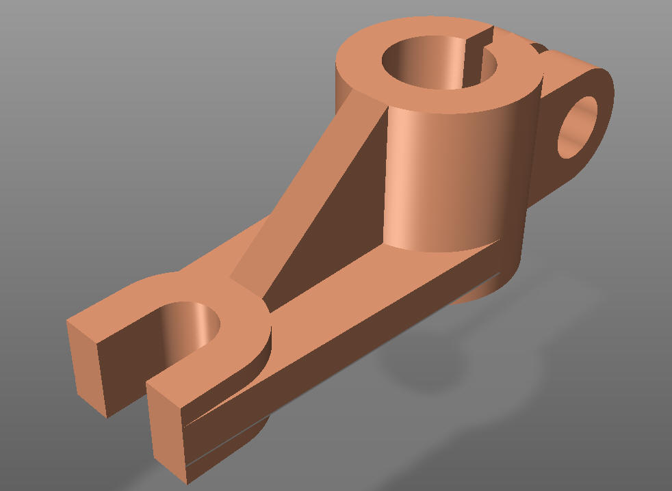
the basic shapes of the part instead of creating a sketch. You can see that in this part.
I saw some Fusion 360 exercises online and I decided to compare
ZW3D. It quickly turned into a study in modeling techniques. I have created
many comparisons to Fusion 360, Onshape, Solid Edge, NX, Creo,
Catia and Inventor lessons to show the difference
between ZW3D and my modeling techniques. I found the presenters working
identically wasting massive amounts of time
with overly complex constrained sketching procedures. I was so unimpressed that
I decided to model the parts or assemblies showing my modeling techniques plus 's superb design system.
Many of these modeling techniques can easily be implemented even
within their existing system. I call it Streamlined Sketching and
Feature Based Modeling. Please review a few of the above ZW3D
comparison lessons, there are some very stark differences.
Please watch
a Solidworks user model this part!
With all the
tedious constrained
sketching for this simple part for the Absolute Beginner, you can imagine a
complex part?
While creating 3D models from drawings is the very best
way to learn 3D CAD and maybe some design techniques it does not
expose the designer to the design flexibility necessary in design. IronCAD is all top down due to the single model environment.
Creating mating parts is a cruise. But modeling is just one aspect of a
well designed productive 3D CAD system.
Solidworks
is a marginal 3D CAD system based on the dated Pro/e history
based modeling system released in 1988. I sold Pro/e years ago
and found it not productive enough
for our engineering department. We use what we sell. That gives us
the experience to effectively support our user base.
I would do a
video, but I really am not good at it. So I will show you step by
step. I will try and get ZW3D support to create one. They are
very good.
The modeling technique is hugely responsible for
the level of productivity. Those of you that are only trained in the
sketch, sketch, constrain, constrain world are truly limited by not
using the freedom of feature based design, that is available in even
the most Solidworks-ish of CAD systems. If your
designers are designing in these very unproductive and time
consuming processes it might be time to review your standard design
processes. Don't have any do you?
These lessons have actually turned into exercises in
modeling techniques as compared to showing a more productive CAD
systems. Again, I say, there are many different ways to model a part.
I see with my exposure to direct edit modelers like CADKEY, I
rarely sketch like you see the Solidworks fellow doing. I have always
created my basic sketches by mostly creating offsets and extending
and trimming or. It seems to be much easier. I never put in a fillet that
can be created later. What do you think?
Since ZW3D
is a sketch based product with a primitive shape option I will
create the model in both processes. The sketched based model will be
done with StreamLined Sketching to show the incredible simplicity
and productivity over the de facto constrained sketching.
I
first go do configuration and set the units to MM.
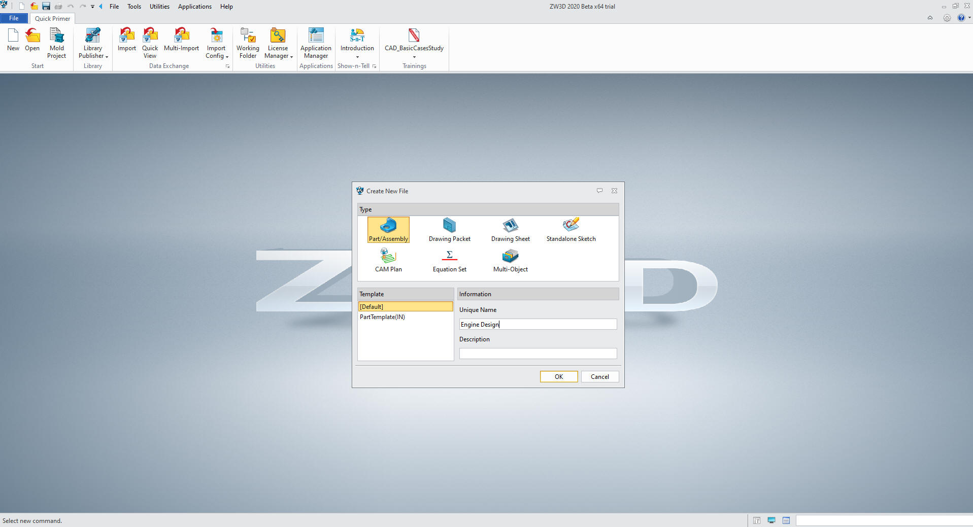
I
create a new Part/Assembly file.
Note: When doing production
design you can use the Multi-Object file to create a part file under
a top file. You then could keep a legacy of modifications or similar
parts in a single file
Modeling with Primitive Shapes
We are already in millimeters so lets get started.
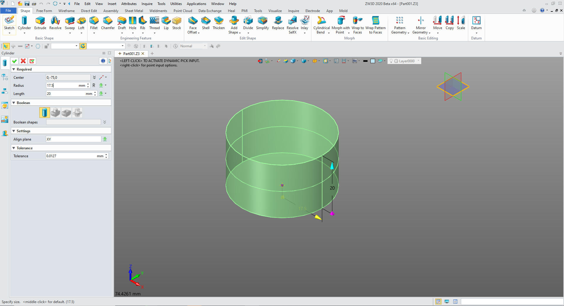
Again
I instantly differ from the Solidworks presenter by inserting a
primitive cylinder and locating it 75MM fromX0Y0Z0 and sizing it.
Note: Pro/e clones have been starting with the sketch for almost
30 years. Even today the sketch is the only option in most programs.
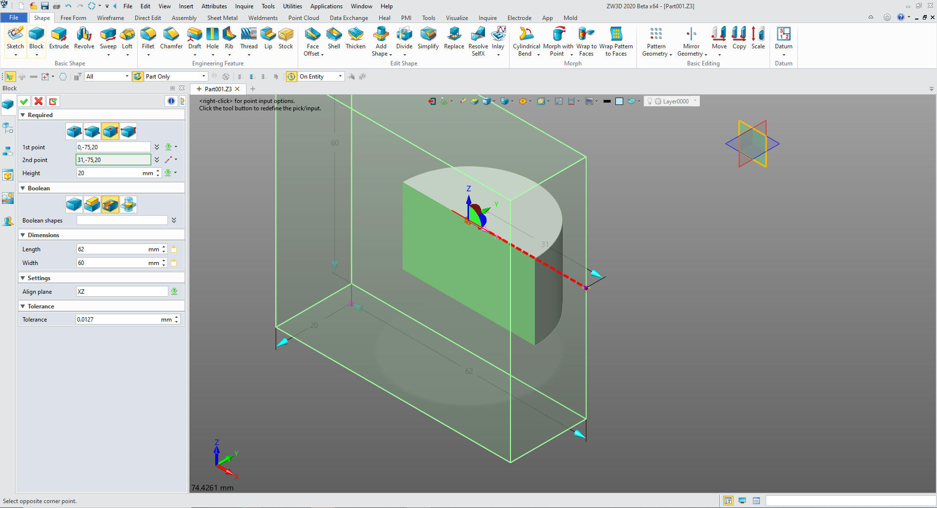
We insert a primitive block on the
cylinder, orient it and size and set it to remove. I am showing you
a new way of thinking. I could do this complete job in sketches but
primitive are more productive and more fun!
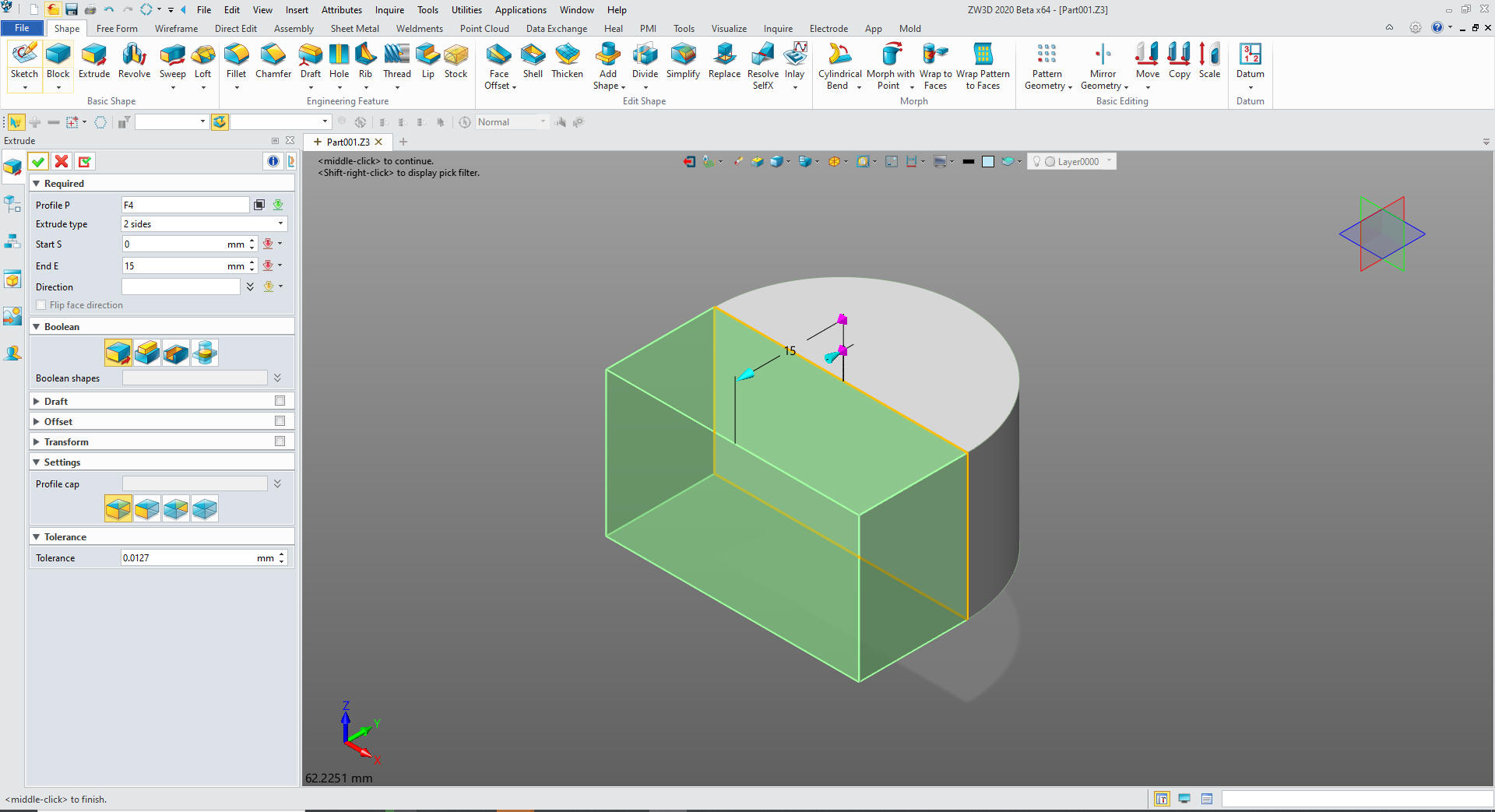
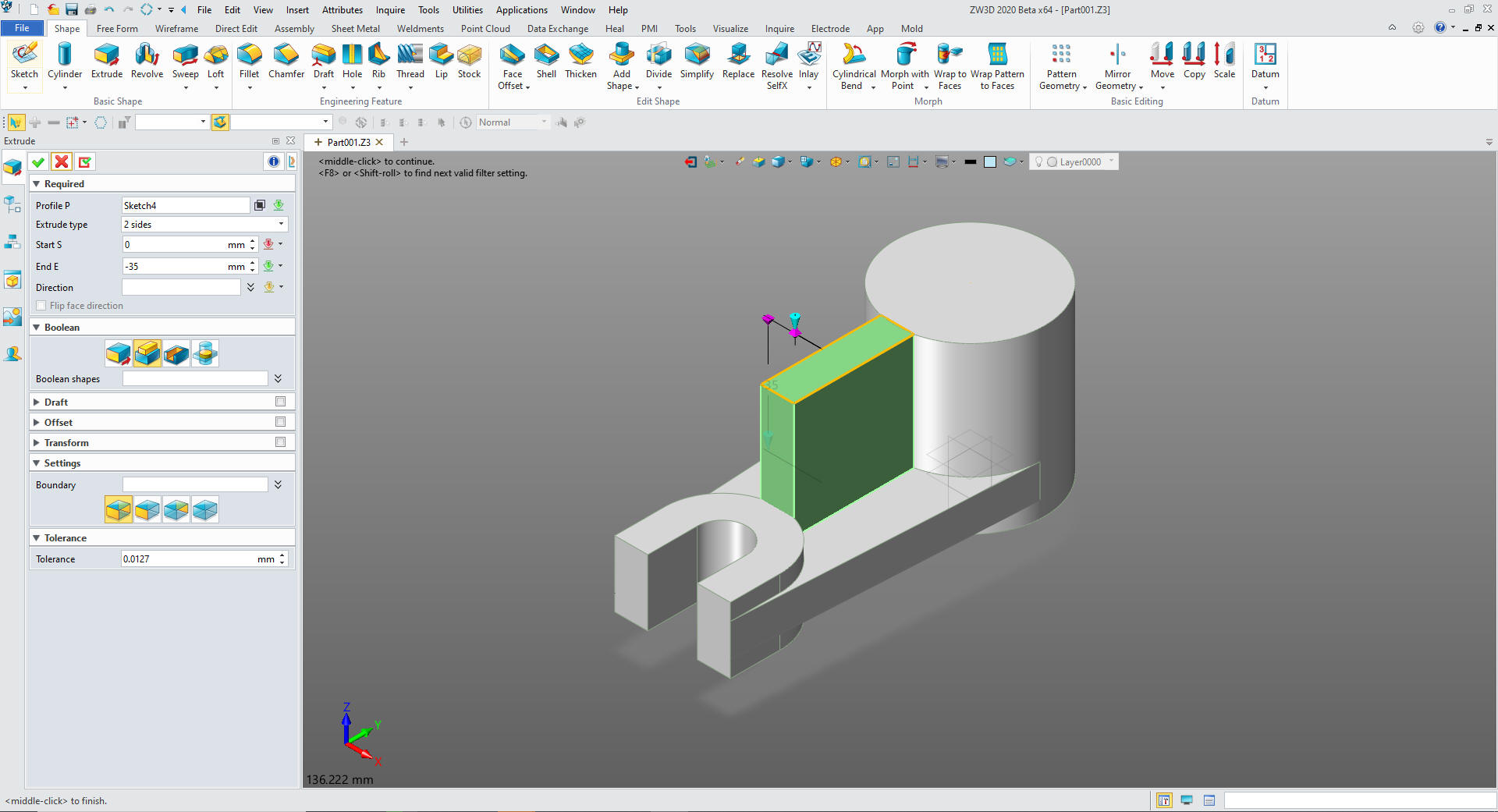
We just extrude the face 15mm and set
it to add so it becomes part of the shape. Nope, no sketch needed!
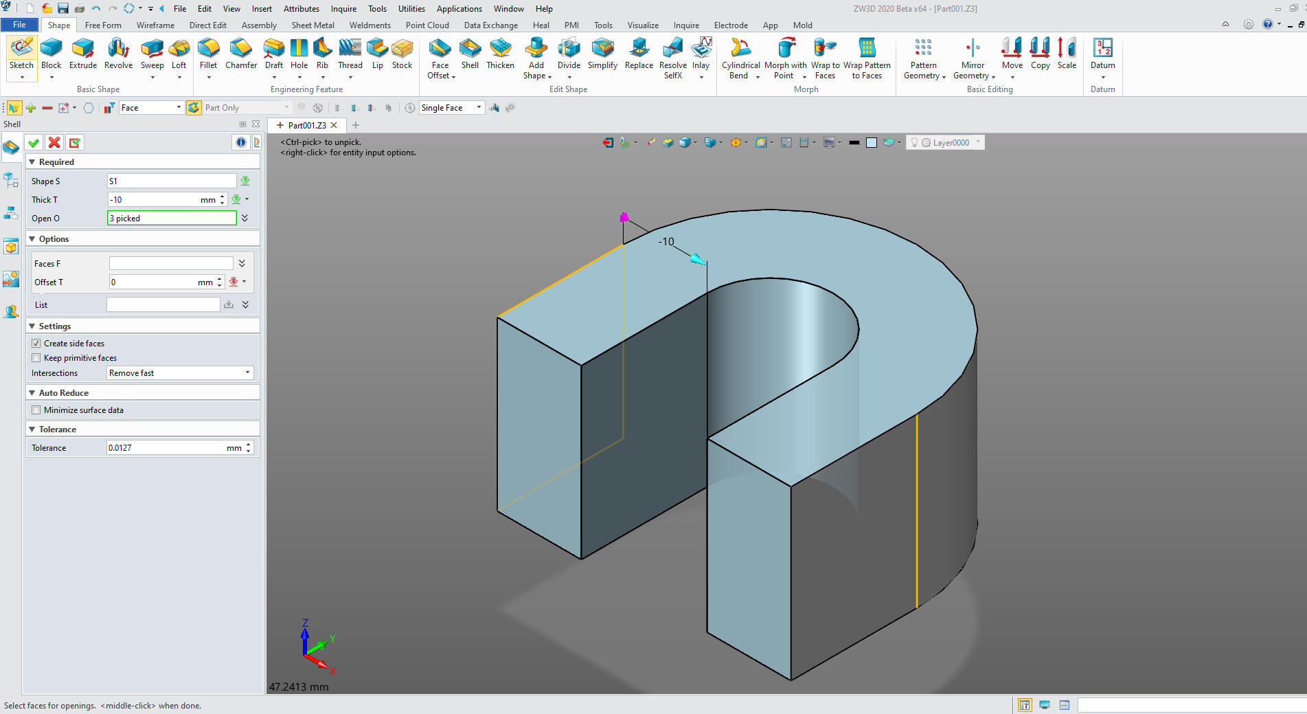
Now do something twice clever. We will just shell the shape. The is
what I call Feature Based modeling. Once you start designing with
shape you look at part design much differently than with constrained
sketching.
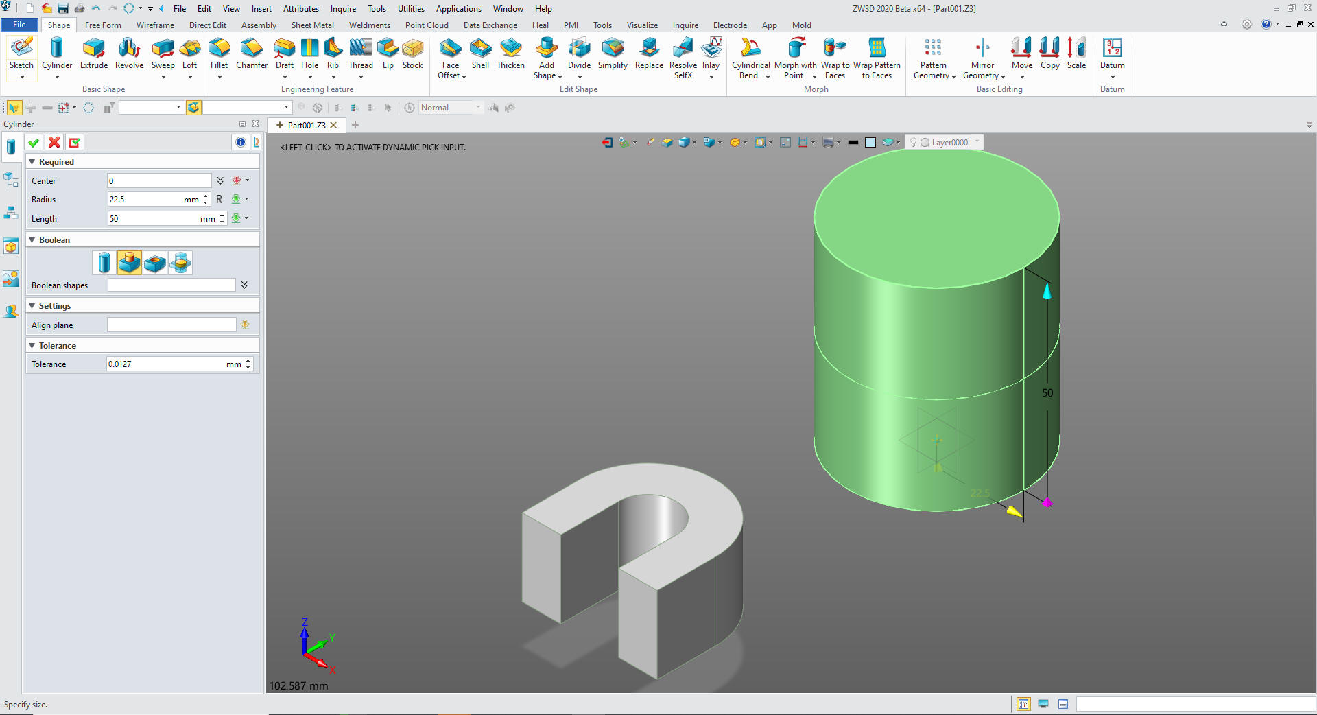
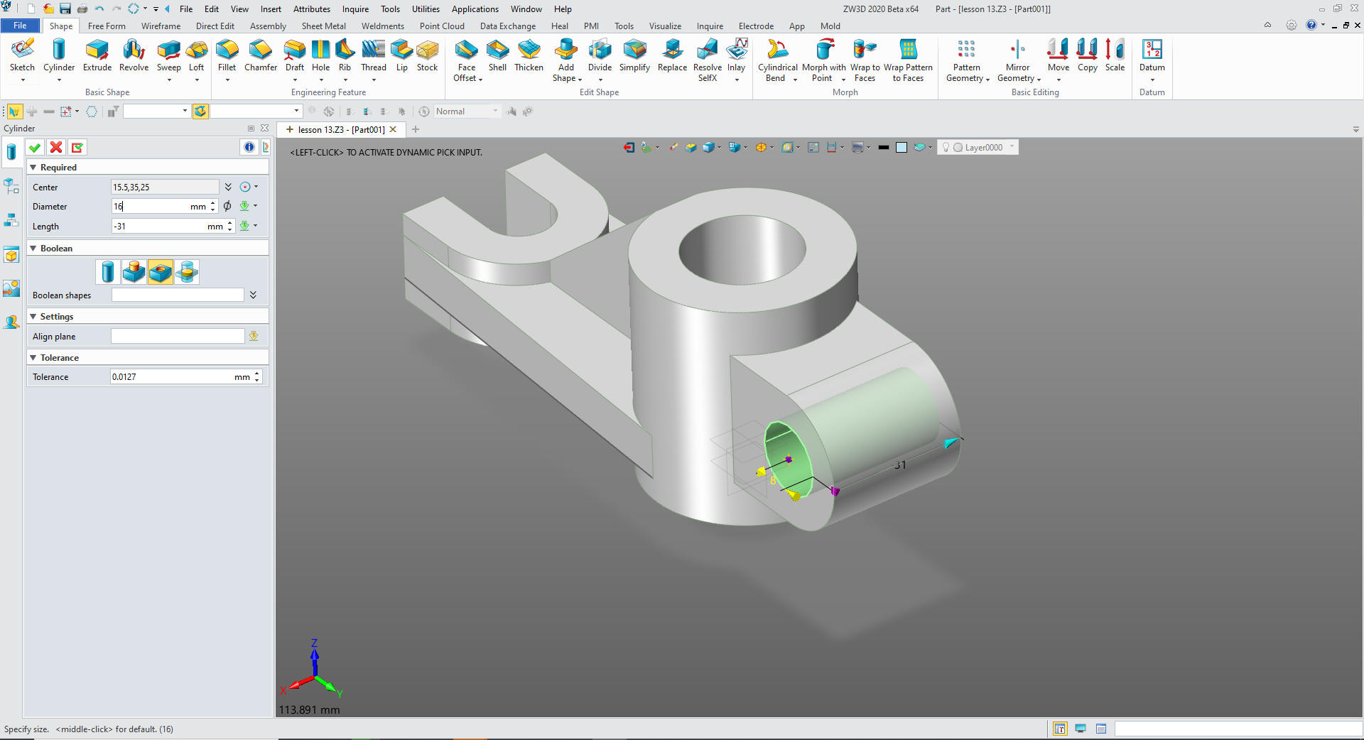
Now
for the main cylinder. We just insert a primitive cylinder at X0Y0Z0,
size it
and set it to add.
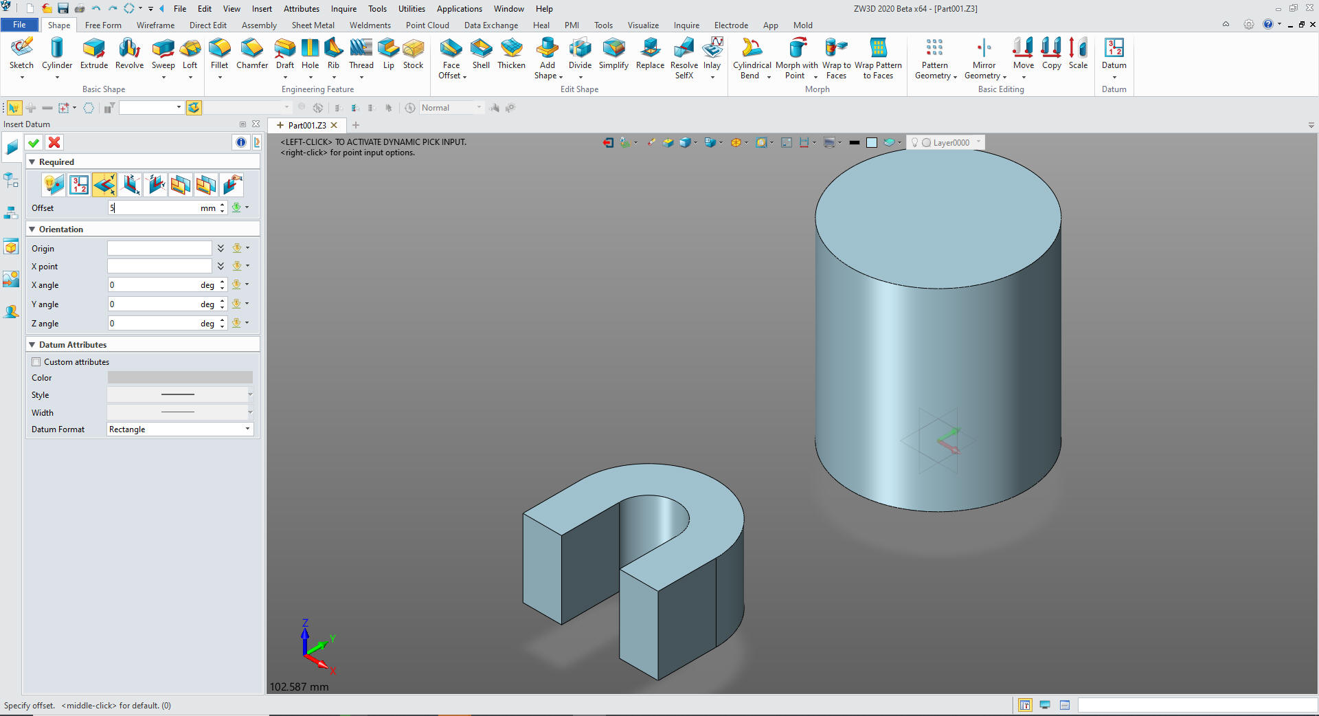
We select the
sketch command, in where it requests plane we select the option and
select insert datum. We select the XY plane and set the offset 5mm.
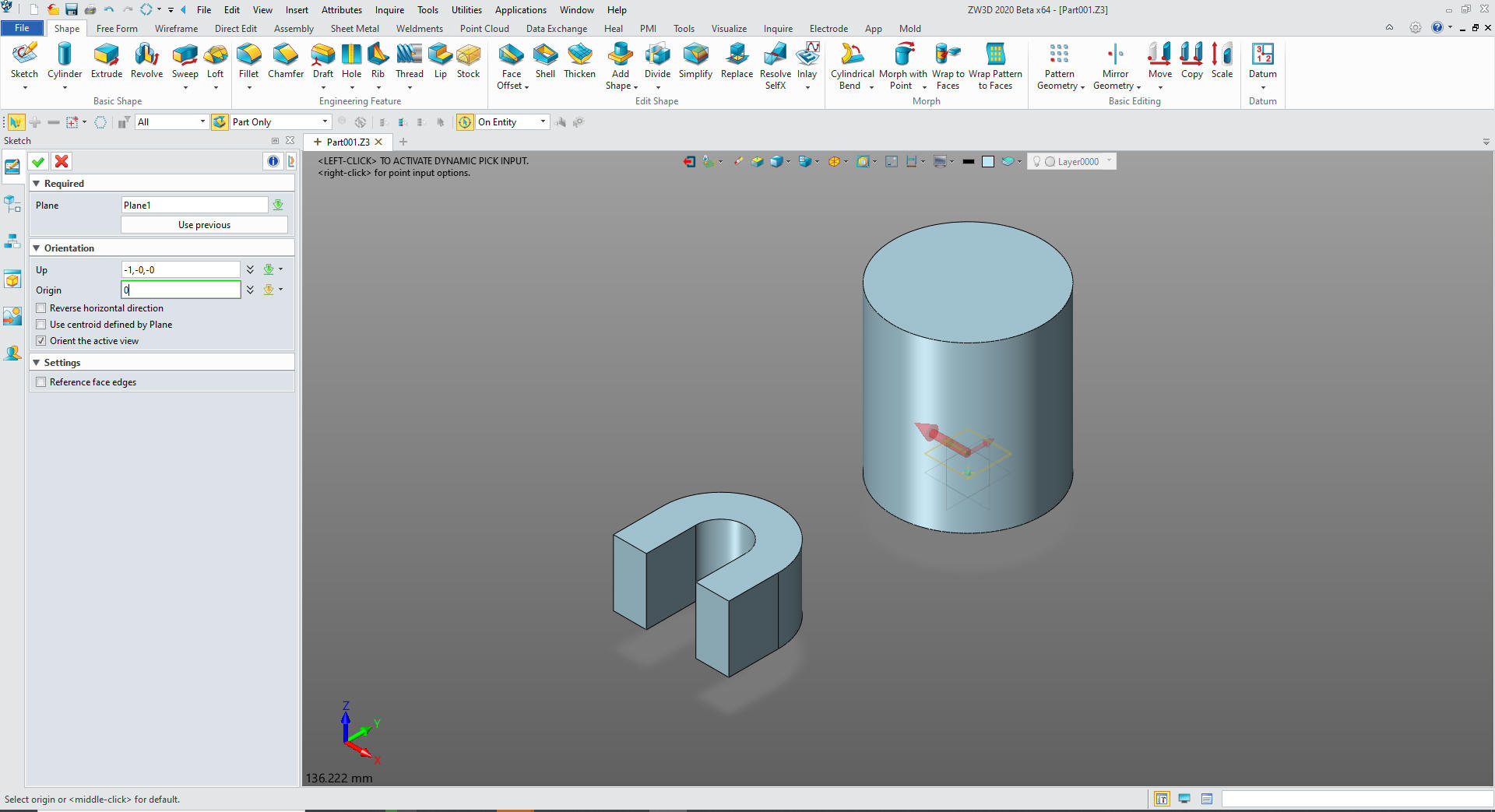
We set
up -X and origin X0Y0Z0
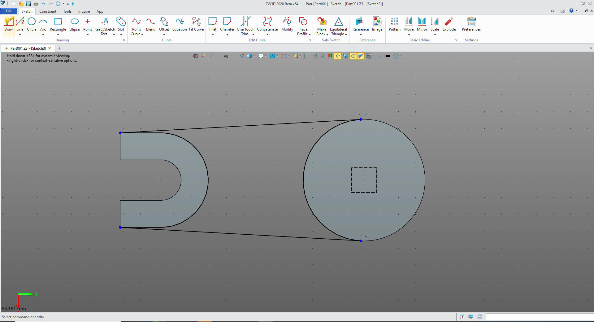
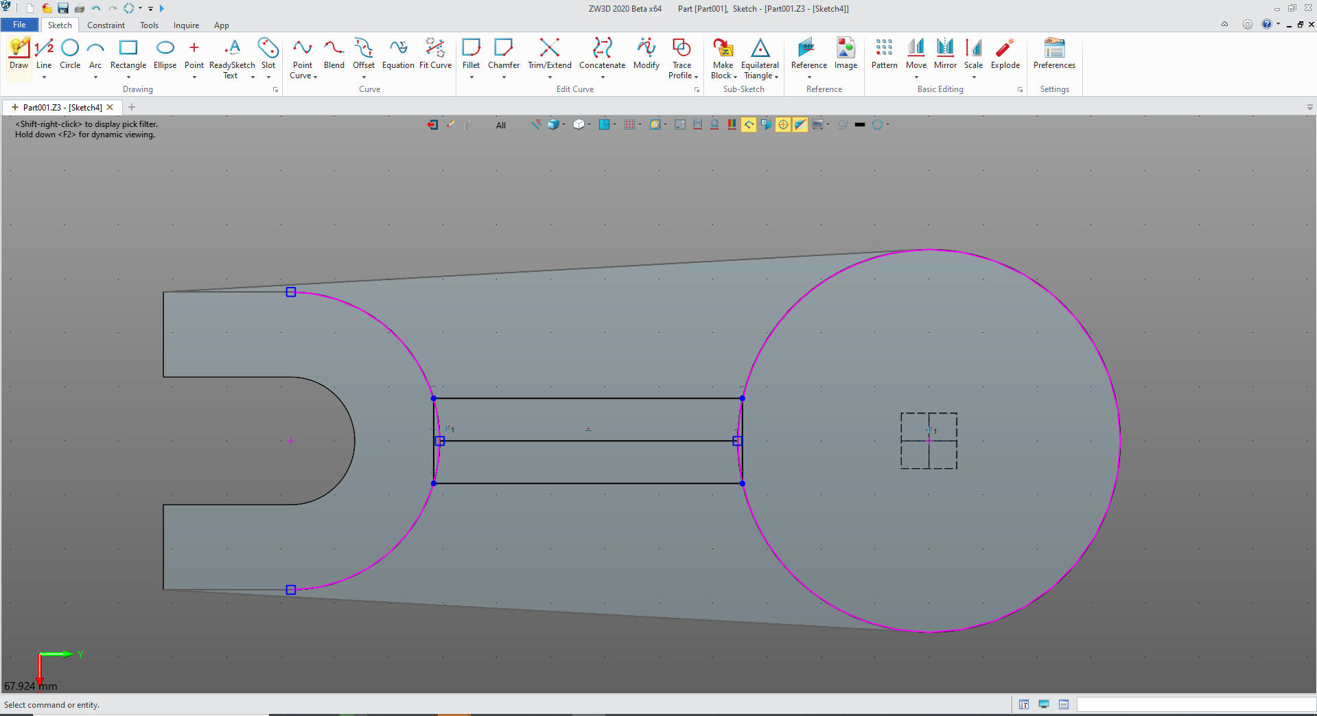
In
the sketch we project the necessary edges and create the two line
making sure they are tangent with the large cylinder. The projected
entities have to be unlinked and converted to usable entities. There
is no constraining, I call this StreamLined Sketching.
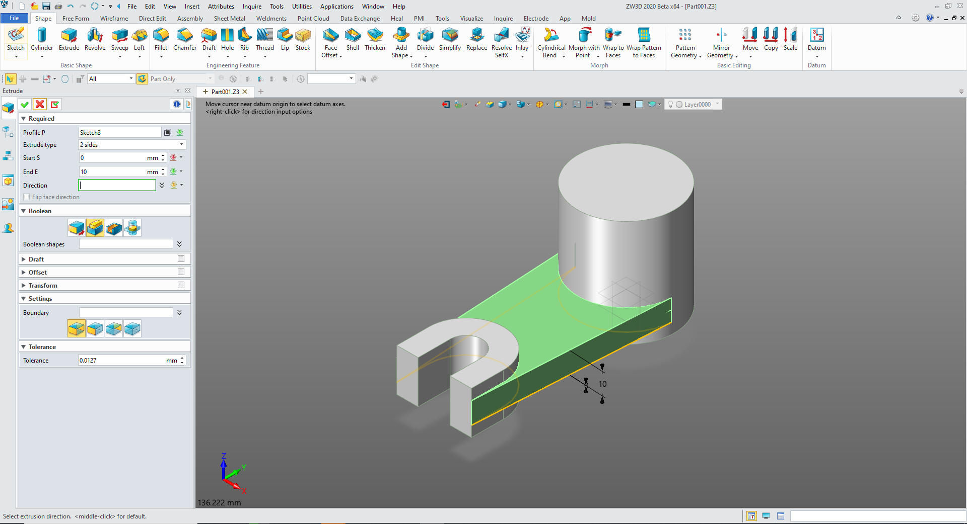
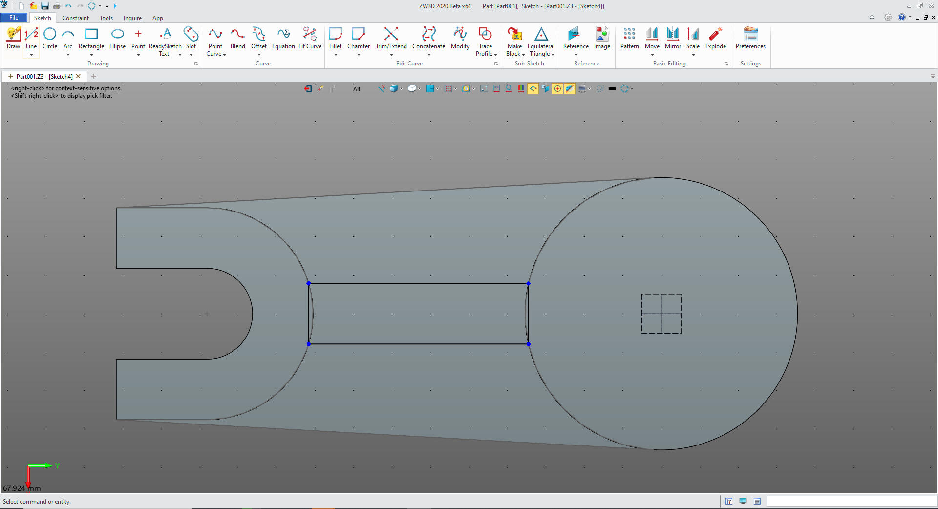
We
exit the sketch and extrude the the profile 10mm and set it to add.
We create a sketch on the top of the cylinder and set up to -X.
We sketch the centerline and set the offset. Project the affected
arcs and extend the lines and then create the two end lines. Here are
the basic graphics.
We
delete the reference entities and we have our finished sketch. Again
no constraints.
We exit the sketch and extrude the profile.
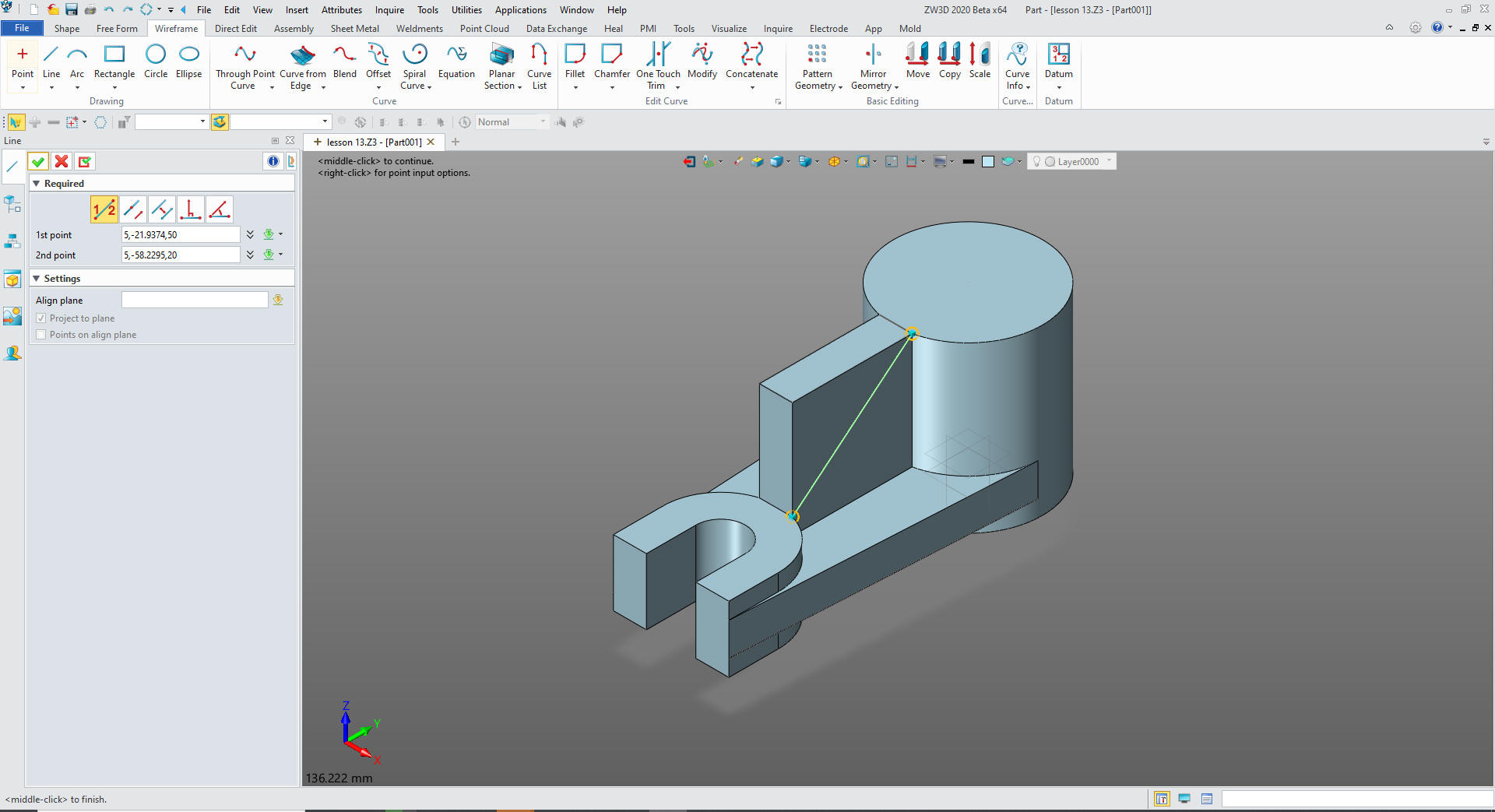
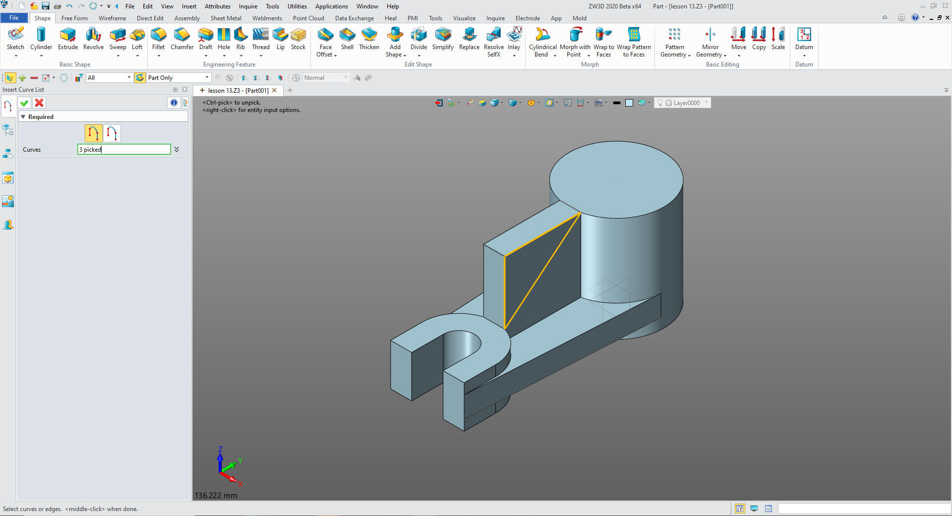
We got to wireframe and create the diagonal line to cut the rib.
We
will now select extrude and in the option we will create a curve
list to create the profile entities. I like to show the other
options than just creating another sketch.
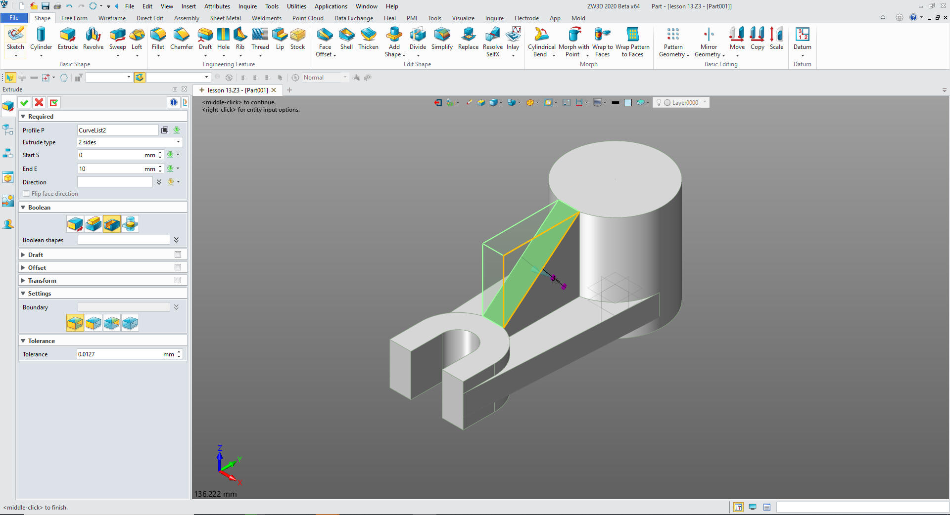
We
select okay and we can now set our extrusion depth and set to
remove.
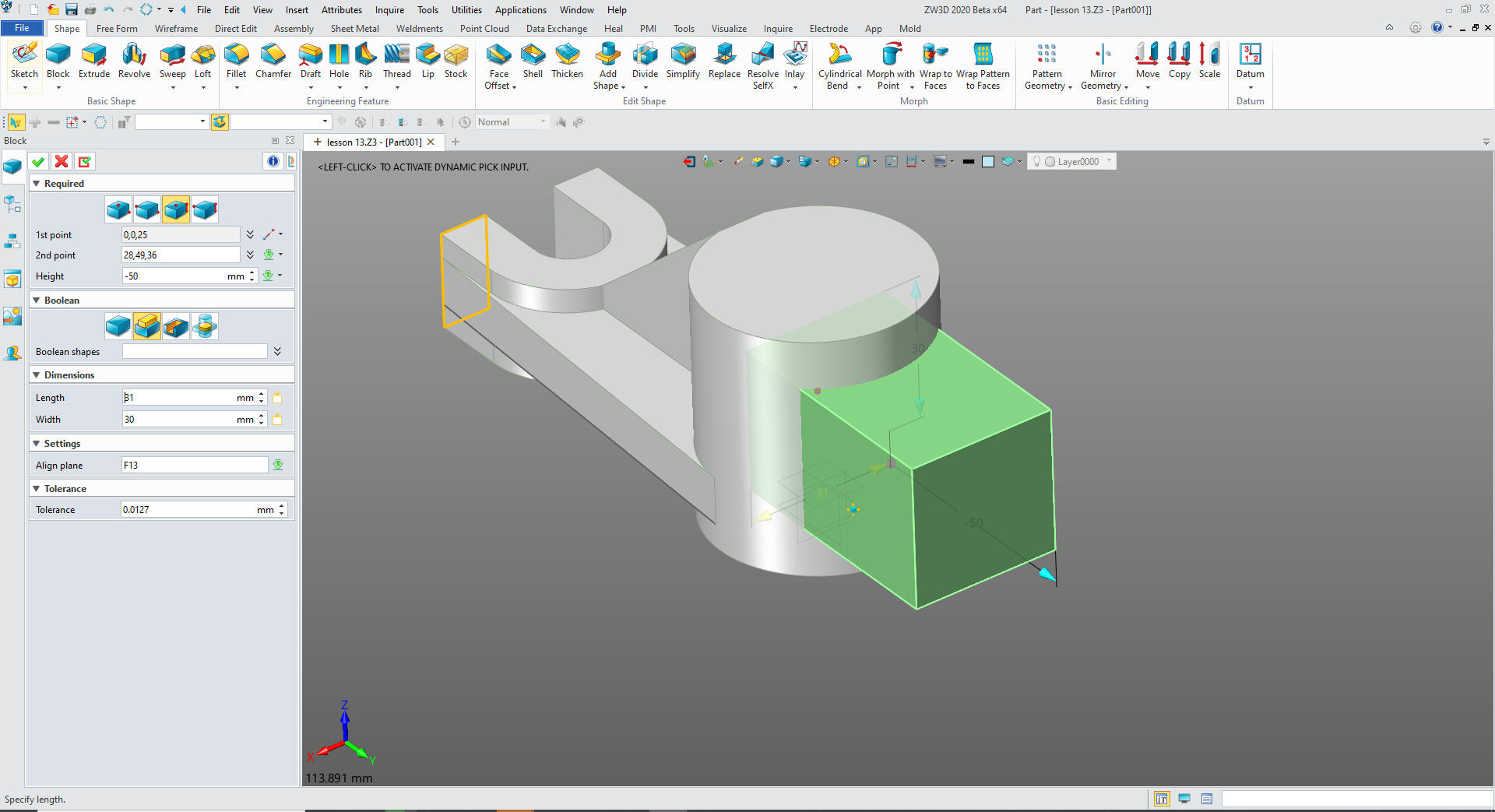
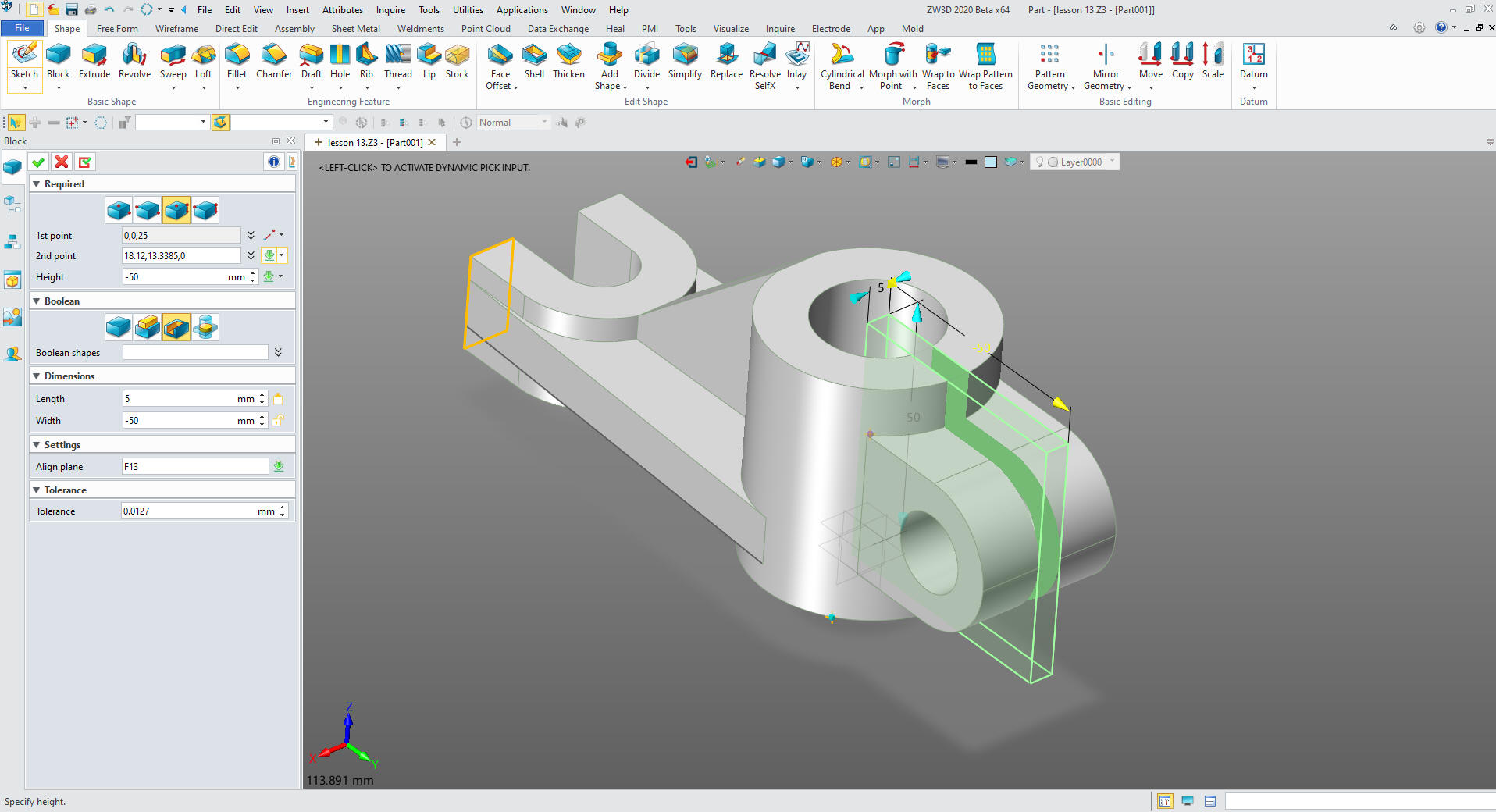
We
insert a primitive block locate, size it and set it to add. You get
very good at manipulating the primitives. It is quite challenging at
first, but is quite fun when you get the hang of it.
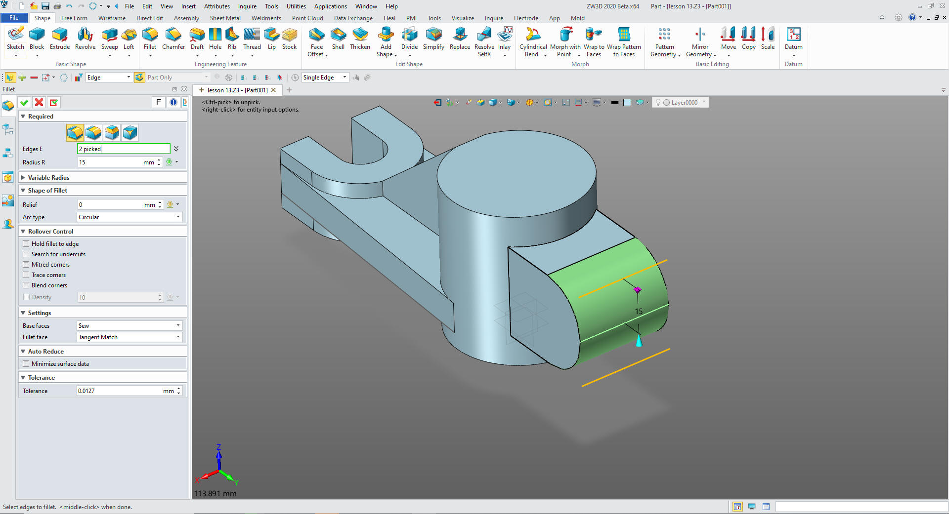
We
create the fillets. We do this now to prepare for the next
step.
Now we will create the hole by inserting
primitive cylinders at the center of the radii, sizing and set to
remove
Now again
we will insert a primitive block located, size it and set to remove.
There you only two
formal sketches and a bunch of fun primitives.
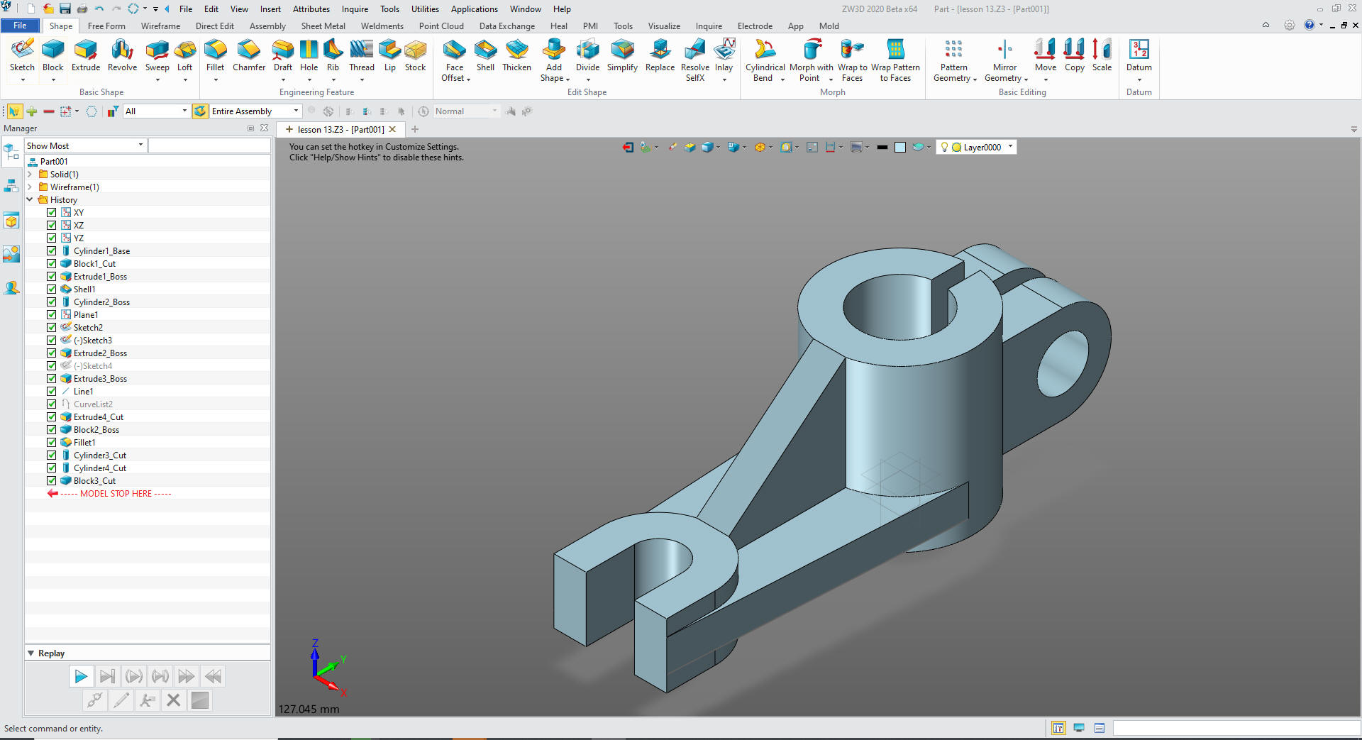
ZW3D not only has the multi-object environment but also has
integrated documentation so you can do complete projects in one
file. This is huge.
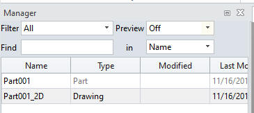
You can see both the model and the
document in the same file under the manager.
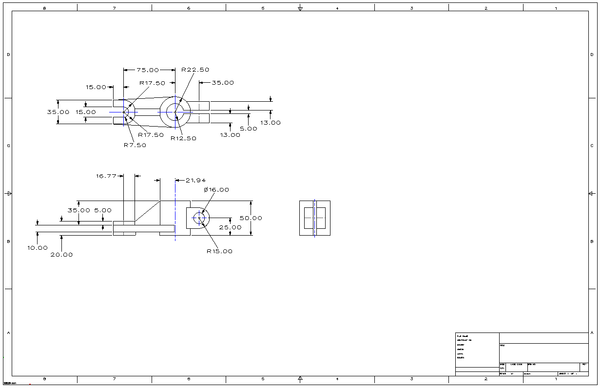
Here is the AID
(Associated Information Document) (drawing).
You can see the two process that ZW3D offers are both hugely
more productive than the tedious constrained based sketching. You
can see more on modeling techniques here.
Give me a call if you have any
questions. I can set up a skype or go to meeting to show this part
or answer any of your questions on the operation of ZW3D. It
truly is the Ultimate CAD/CAM System.
If you are interested in adding professional
hybrid modeling capabilities or looking for a new solution to
increase your productivity, take some time to download a fully
functional 30 day evaluation and play with these packages. Feel free
to give me a call if you have any questions or would like an on-line
presentation.