|
Tech-Net News
Leverage Your
Simplifying Your Design Process
IRONCAD/INOVATE
INOVATE TRANS
|
TECH-NET, Inc. welcomes you to our website. You are heading in the right direction by looking to us to help you fill your 2D/3D CAD/CAM needs. TECH-NET, Inc. is an authorized reseller for IRONCAD, ZW3D, ROLAND Milling Machines and Scanners, CTL Computers and Pro-Star Notebook Computers and much more. We provide comprehensive solutions including software, workstations, peripheral hardware, training, support and engineering services. Tech-Net, Inc. uses the software and hardware that we sell in our own engineering division. We feel with this hands-on knowledge and experience we can offer the the highest level of service and support. This allows us to:
"Maximize Your Productivity and
|
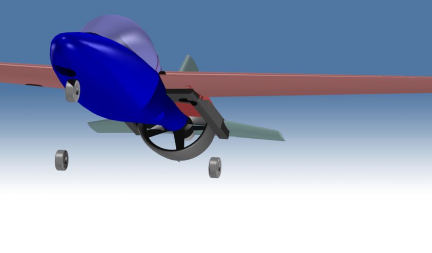
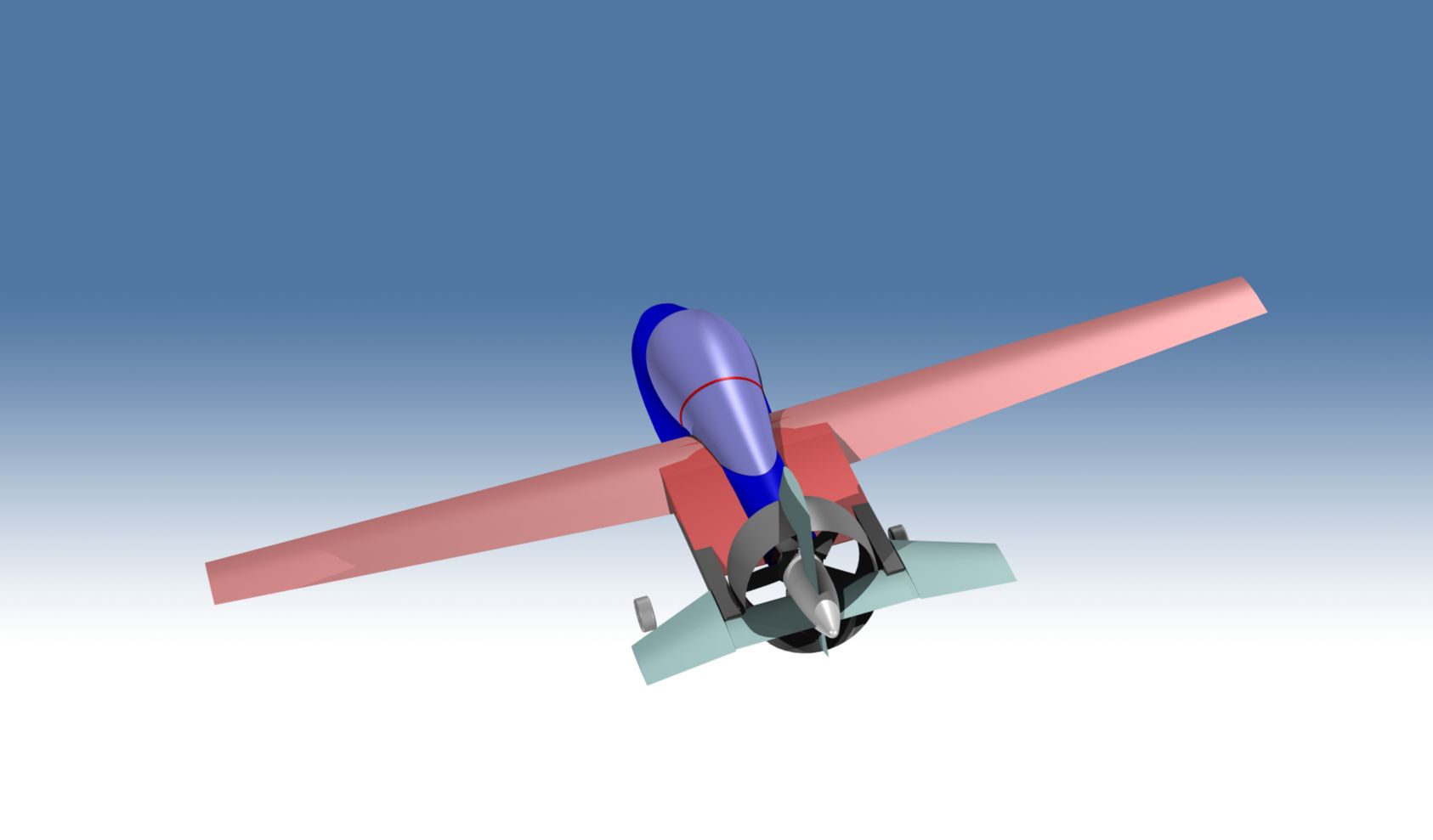
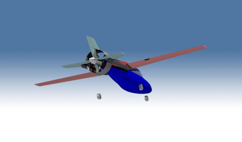
Rendering of the Month
Jeff Miller's |
|
Products |
||