|
THE LOST CAD PARADIGM!
HOW I FOUND FREEDOM IN AN UNFREE CAD WORLD!

Both the Parametric History/Feature and Direct Edit based solid modeling paradigms are now available in most of the popular programs, now I am going to introduce you to a third called “Innovative Design” the lost CAD paradigm.
The Worst to Best CAD System and Why!
IronCAD vs Solidworks and the Pro/e Paradigm
Let’s start with a bit of history.
Parametric History/Feature Based Solid Modeling Paradigm
 This format was introduced with Pro/Engineer in 1987. It is a somewhat complicated design system. It has a very precise history base parent/child feature construction system. The parts have to be created in a certain way. Enter “Design Intent”. You have to really understand your design before you start creating the part or assembly. You have to understand how it is to be made and dimensioned. It should have really been called Pro/Designer. If the part is designed correctly you can have an automatic drawing. This is probably where the focus on the engineer being a CAD designer started. Now don’t get me wrong Pro/E is a very good program with many add on analysis functions, which does make it a good tool for engineers. This format was introduced with Pro/Engineer in 1987. It is a somewhat complicated design system. It has a very precise history base parent/child feature construction system. The parts have to be created in a certain way. Enter “Design Intent”. You have to really understand your design before you start creating the part or assembly. You have to understand how it is to be made and dimensioned. It should have really been called Pro/Designer. If the part is designed correctly you can have an automatic drawing. This is probably where the focus on the engineer being a CAD designer started. Now don’t get me wrong Pro/E is a very good program with many add on analysis functions, which does make it a good tool for engineers.
This system is very complex and hard to learn, causing the user to have to be a regular user. When you design a part the features are based on the earlier features. The skill and expertise of the user is paramount when using this system. When designing a part an experienced users has few problems. The problems show up when you have to change the part. The original designer can have problems with his own design if he is away from it for only a month. But the designer that has to take over the job may not be able to make the changes and may have to recreate the part. If this is a released part this can be very dangerous.
This format has three modules. A part, assembly and a drawing. This means you have to start naming parts as you begin your design. All parts are external. You can design in the assembly mode which doesn’t seem to be a problem. But PDM becomes a problem even if you are working alone.
The Pro/E paradigm became the de facto standard. Soon Solidworks showed up, started with the help of some ex-PTC developers. It was soon purchased by Dessault Systemes which soon implemented this paradigm in its Catia 5. UG was releasing Solid Edge in 1996. Autodesk Inventor soon followed in 1998.
All of the above product use the Pro/E paradigm and all have the same problems. A very structured design process. It was soon found that this paradigm was very limited in interoperability. They could not use any of the others systems data. With Solidworks there were attempts to automatically create the history from non-native files but it was marginally successful. Even now you can recognize features but it leaves a lot to be desired.
Explicit or Direct Editing Solid Modeling Paradigm
I was selling CADKEY in 1996. CADKEY was a wireframe modeling package. There was a surfacing package called Fastsurf. Both programs offered a very good modeling package. Solid modeling was introduced in as FastSolids, this was a direct editing solid modeling system. I started my solid modeling at that time. The only other solid modeler at the time was Pro/E and it was my only competition. But it of course was in a different class offering much more engineering analysis.
CoCreate was also around at this time. It was a direct editing program. Now is being offered as a standalone product within PTC Creo. It can be worked with PTC Wildfire offering the advantage of direct editing. PTC knew that they need this functionality to be able to work with non-native parts from other products, such as Catia and Siemens NX.
A new product, SpaceClaim, was created to fill this gap, but like CADKEY is a direct edit only package. I feel you really need both paradigms to have a flexible design environment. Take a look at this article
CONCEPTUAL DESIGN!
Which CAD Paradigm is Best?
So today PTC Creo (Pro/E with CoCreate), Siemens NX (Solid Edge) with ST (Synchronous Technology), Autodesk Inventor with Fusion and now with soon to be released Solidworks Mechanical Conceptual all offer Direct editing. They see the writing on the wall. Today we need both paradigms. Catia 6 is supposed to have it also, but those large companies that use Catia, like Boeing are probably a bit gun shy to move from Catia 5 due to the fiasco with the last move from Catia 4 and the incompatibility with the two versions, which they are still suffering. I am sure Boeing would have not purchase Catia 5, but now are stuck with it.
IRONCAD provides the ability to design different types of parts in a single modeling environment to fit the needs of the designer and the task at hand.
Each part design types have unique behaviors that benefit different aspects of design as follows:
IRONCAD Structured Part Design
 I have using and selling IRONCAD since the mid 1990’s. I have been happily using IRONCAD from the middle 1990’s. I have enjoyed using both the history and direct edit functionality. But to my surprise I have been using the Innovative Design Environment. Kevin, the AE from IRONCAD showed us the Structured Part Design Environment. With a touch of a switch you start working in either environment. You can actually design in the familiar Pro/e paradigm, but of course, still having the incredibly productive drag and drop functionality. Below shows more information on the Structured Part Design. I have using and selling IRONCAD since the mid 1990’s. I have been happily using IRONCAD from the middle 1990’s. I have enjoyed using both the history and direct edit functionality. But to my surprise I have been using the Innovative Design Environment. Kevin, the AE from IRONCAD showed us the Structured Part Design Environment. With a touch of a switch you start working in either environment. You can actually design in the familiar Pro/e paradigm, but of course, still having the incredibly productive drag and drop functionality. Below shows more information on the Structured Part Design.
Structured Part Design is a history-based structure of features that build the design following a intended design order determined by the user. This part design allows the user to define a rigid sequence to their design that can be predictably changed based on the intent provided by the user. During the design process, users can "rollback" to any stage of the design to edit the feature definition at the stage in which the feature was created. After this modification, the remaining features will update accordingly to the changes applied.
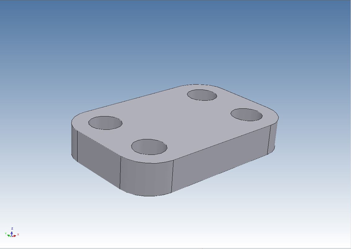
Structured Part Design also provides a powerful multiple body capability to aid the user in designing the part that could be made up of 2D Sketches, features, 3D curves, and surface features. Using command tools such as Boolean, users can combine the multiple bodies as a feature operation event which allows the user to fully edit the underlying definition at any stage to alter the design. Below we put in the holes using the center of the corner radii. When we pull on the block the holes stay centered on the corner radii.
The Lost CAD Paradigm.
I have using and selling IRONCAD since the mid 1990’s. Using Innovative Part Design, I thought I was using history/feature based solid modeling. Lately I had the chance to train on both Solidworks and Inventor and found working in a structured part only design paradigm very limiting. Below is the Innovative Part Design mode I have been working in for years. And basically thought that all history based systems were similar, except for the added drag and drop functionality.
IRONCAD Innovative Part Design
Innovative Part Design allows users to build a non-restrictive history of features that make up the design aspects of the part. Although it has a history of features, the system allows the user the ability to dynamically change the history order without inverse effects of feature dependency rules and restrictions. SmartUpdate technology within Innovative Part Design aids the users by intelligently managing the feature history giving predictable results when changes are made by the user. Innovative Part Design also provides a level of flexibility by allowing the user to refer to geometry elements regardless of the history order in which the geometry appears. This flexibility allows the user to work as if they were working with a physical object in their hands eliminating rules defined by the system.
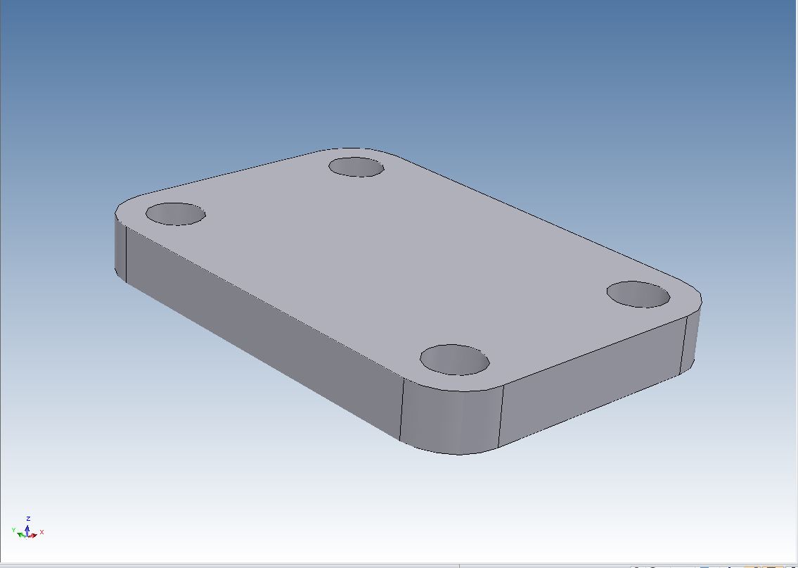
Since the Innovative Part Design supports features, users are able to add specific design rules to create parametric design intent. The advantage in this approach is to apply intent when needed allowing the user to place only the critical design intent during their design process without the need of system applied rules that may not apply to their design task. Below we put in the holes using the center of the corner radii. When we pull on the block the holes stay centered on the corner radii. Now of course we can constrain the holes if required.
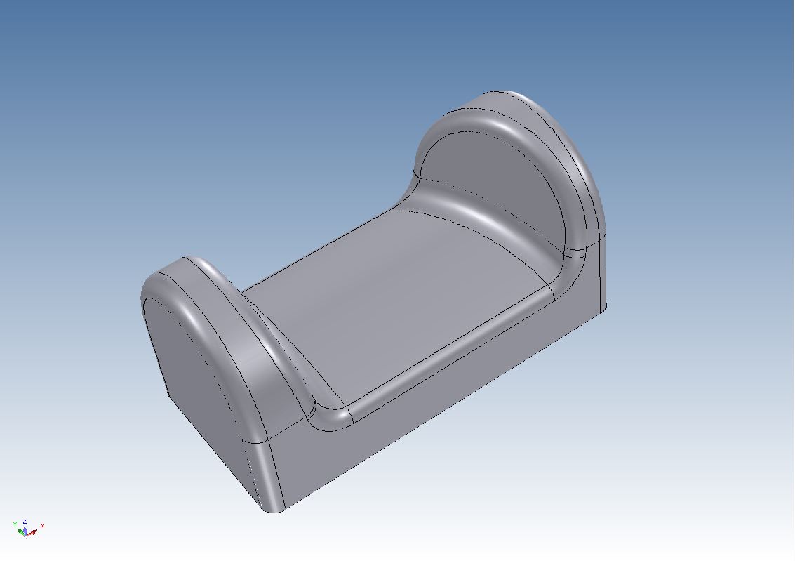
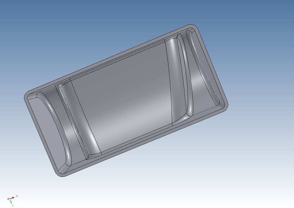
IRONCAD DFM – Direct Face Modeling
In addition to the non-restrictive history based capabilities, users are able to directly edit the geometry regardless of the underlying definition of the feature. This capability allows the user to work on imported data containing no feature information directly as well as the Innovative Parts with feature information. Unlike other direct geometry systems, IRONCAD will maintain the feature design information that is not affected by the direct geometry modification, creating the only application that can truly support a mixed feature environment. This is not a separate module or even a separate feature in the program, it is integrated functionality available at a click of the right mouse button.
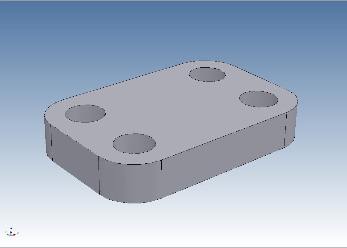
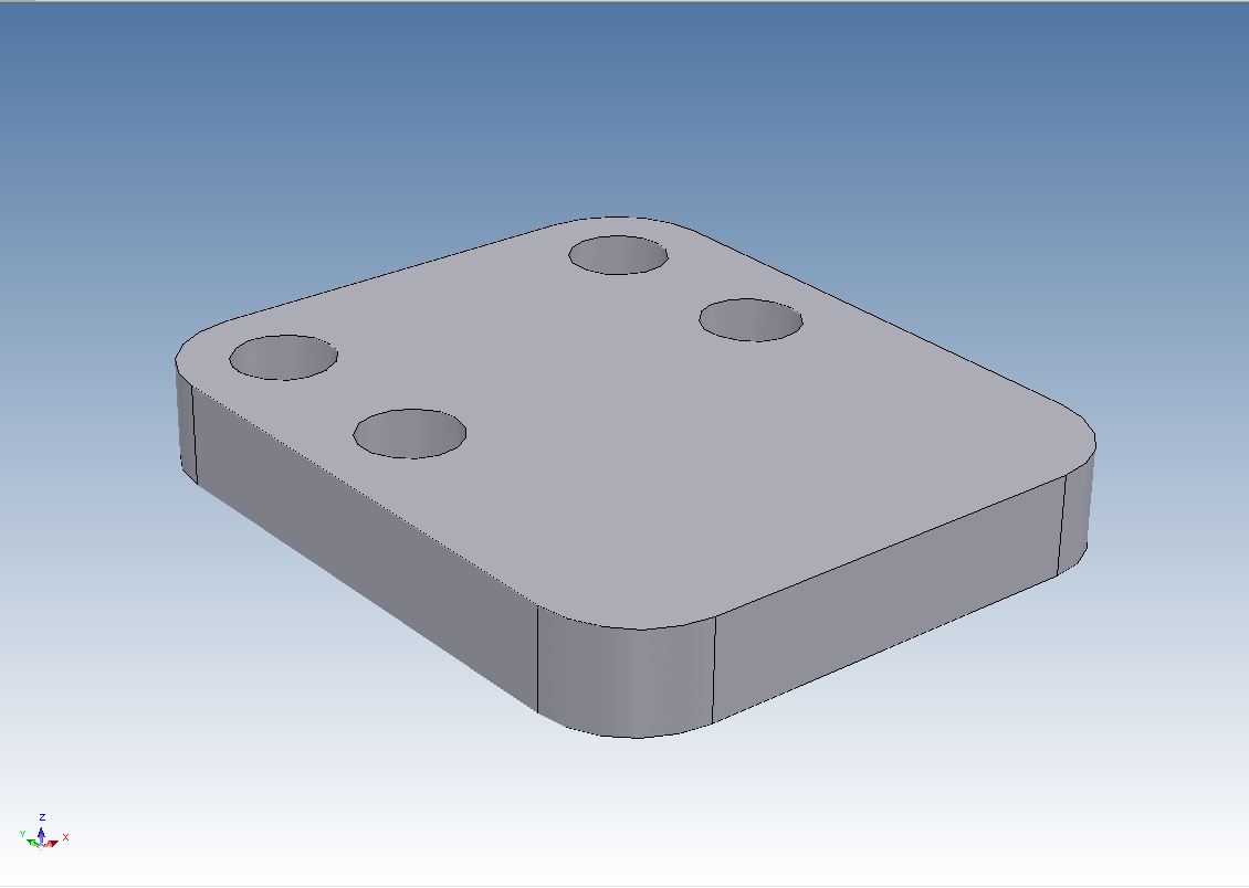
DFM – Direct Face Modeling (DFM) allows model modifications to be made irrespective of the previous feature history or in cases where it does not even exist. Being able to directly overwrite feature history when desired results in tremendous productivity gains over the process required by today’s feature based systems. DFM is very effective when working with imported b-rep geometry that does not have feature history. Today’s systems have to rely totally on feature recognition but when that fails they do not have an alternate editing method. Unlike this limitation, IRONCAD can treat an imported b-rep model as if it was created natively using DFM. Below is an example of modifying a face in a part. To do this in a Pro/e paradigm part you would have to have the design intent from the beginning of the part. With IRONCAD you can be innovative and are free to design on the fly without any consideration for design intent.
 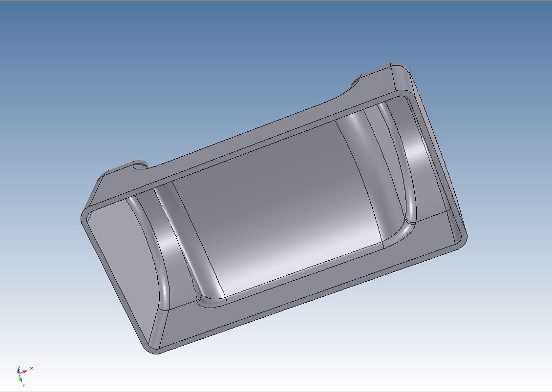
Now we rotate the face and notice all of the blends and shell are updated.
Conclusion
IRONCAD/INOVATE offer the functionality that many, even the high end, CAD systems offer in separate modules if they offer it at all. IRONCAD/INOVATE offer a much higher level of operation and productivity in one easy to use space. It also offers UDE (Unified Design Environment), the ability to work on assemblies in one file. This offers a incredible advantage over the standard Pro/e paradigm of separated part and assembly files. See more information in our article “UDE (Unified Design Environment)” file. This offers a incredible advantage over the standard Pro/e paradigm of separated part and assembly files. See more information in our article “UDE (Unified Design Environment)”
The IRONCAD Difference:
The IRONCAD Difference is the increased productivity and design freedom experienced when using IRONCAD’s radically new Creative Design approach.
Creative Design can best be described as:
· The freedom to design without the end in sight
· The freedom to choose when and where to apply design intent and constraints
· The freedom to change ones mind without having to rebuild the model
· The freedom to load another’s design and modify it without fearing the unexpected
If your CAD product does not offer all of this productive functionality, please take a look at IRONCAD or INOVATE. Yes there is an alternative to the dated Pro/e paradigm. A program that has both the Parametric History/Feature (Structured and Innovative) and Explicit based solid modeling integrated into one system. A program that is much easier to use. As the industry slowly moves toward a standard of interoperability, we will always want the quickest and simplest way to do our design, IRONCAD/INOVATE offers that alternative solution at a very cost effective price.
We sell and support IronCAD
and ZW3D Products and provide
engineering services throughout the USA and Canada!
Take a look at
IronCAD Compose!... You can read most any popular CAD native files directly for review and virtually any kind of communication.
Our
Products!
IronCAD
Four Functions that Increase CAD Productivity!!
IronCAD vs Solidworks and the Pro/e Paradigm
Current
Pricing
and
Specials!
IronCAD
Compose!
– Free!!
More
than a
viewer -
It
configures
and
communicates.
IronCAD
Compose
Pro!
Adds
the
ability
to read
and
utilize
date
from all
the
standard
format
plus
Pro/E, NX,
Catia
4/5,
Solidworks
and
Inventor.
INOVATE
The CAD
Translator
with an
Edit
Button.
Truly
the most
useful
tool and
best
value in
the CAD
market
place.
IRONCAD
Thousand
less
than
mid
range or
high end
programs.
Unmatched
ease of
use!
IRONCAD/INOVATE
TRANS
Includes:
Import
of
PRO/E,
UG
Siemens,
Solidworks
and
Autodesk
Inventor.
Import
and
export
Catia
5.
Note:
Catia 4
import
and
export
included
in
Standard IRONCAD/INOVATE.
IRONCAD
and
INOVATE
import/export
all of
the
standard
formats
plus
Catia 4.
DOWNLOAD
IRONCAD
For
a 30 day
fully
functional
evaluation
of
IRONCAD
or
INOVATE
and
start
playing
and
enjoying
how CAD
design
can be
fast and
fun.
Incredible CAD Combo
Make sure you review the above article.
It shows a great example of interoperability!
Please take a look at our other product!
ZW3D - The Case for Inexpensive Integrated CAD/CAM!
Current
Pricing
and
Specials!
Give us
a call
when you
get any
of our
products
downloaded
and we
will set
up a gotomeeting
and give
you a
demonstration
and some
tips
See you
online.
Joe
Brouwer
Skype:
tech-net-inc
|