|
ZW3D is
similar to the Solidworks clones with four distinct advantages:
- Multi-Object Environment - Parts
and assemblies in a single file
- Primitive Shapes - Using
primitive shape increase productivity 30%
- Integrated Drawing -
Solves many of the PDM and PLM problems
- Usable Robust Integrated Direct Edit
Functionality
We have the native ZW3D and STEP File Available here for download
Note: IronCAD native files must be copied
to the same folder.
3D Modeling is the basis for our
engineering. That is the only place where productivity is paramount.
You can have all the PLM/MBE gurus debating data management, but it
does not add one smidgeon of productivity to the design process.
Top down or
In-Context modeling is the most productive feature of 3D CAD. Most
systems tout this but each part is still and external part. We are
talking about a single model of multi-object design environment.
Both of the systems we represent offer this as the "normal" design
process. Thereby increasing your productivity 20 to 30%.
In these exercises I not only focus on modeling techniques, but
also on much more productive systems to do our designs. I hope you
enjoy them and learn something. If you are in management, understand
that all 3D CAD systems are not the same. Cutting your engineering
costs is very simple. Even your legacy data is not a problem. Please
feel free to give me a call. There are millions of man hours wasted
every day with poor modeling techniques and ineffective 3D CAD
systems that cost a fortune. Productive 3D CAD systems do not have
to be expensive.
Joe Brouwer
206-842-0360
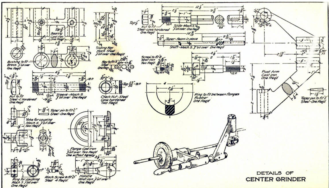
I am doing the below assembly for
an exercise showing my modeling techniques and, of course, my 3D CAD
solutions.
3D CAD Modeling Techniques
I saw the following video challenges on linkedin and thought I would
give them a try.
These exercises started out to show the benefits of
ZW3D over Fusion 360, but
quickly turned into a study of modeling techniques. Take a look at all of
them, they will open your eyes to a much different and more productive way of
modeling. I call these techniques Streamlined Sketching and Feature Based
Modeling. It really has more to do with modeling technique than it has to do
with the 3D CAD systems. I have found that I do 3D modeling as compared to
the conventional 2D sketching. Of course, having a more productive 3D CAD
system doesn't hurt.
ZW3D vs Fusion 360
ZW3D is very similar to the Pro/e
clones with a few small differences. It is very easy for those users
to get up and running with ZW3D. It has a few operation that
are a bit more streamlined. The benefits over the other systems
are the multi-object environment with the integrated drawing. You can
do parts, assemblies and drawings in one file.
These exercises were incredibly
popular and I thought I would follow up by showing more examples of
this 3D modeling technique.
We will be doing a
couple of parts each weekend in both IronCAD and ZW3D. I hope you
enjoy these exercises and hopefully they may lead to increasing your
productivity.
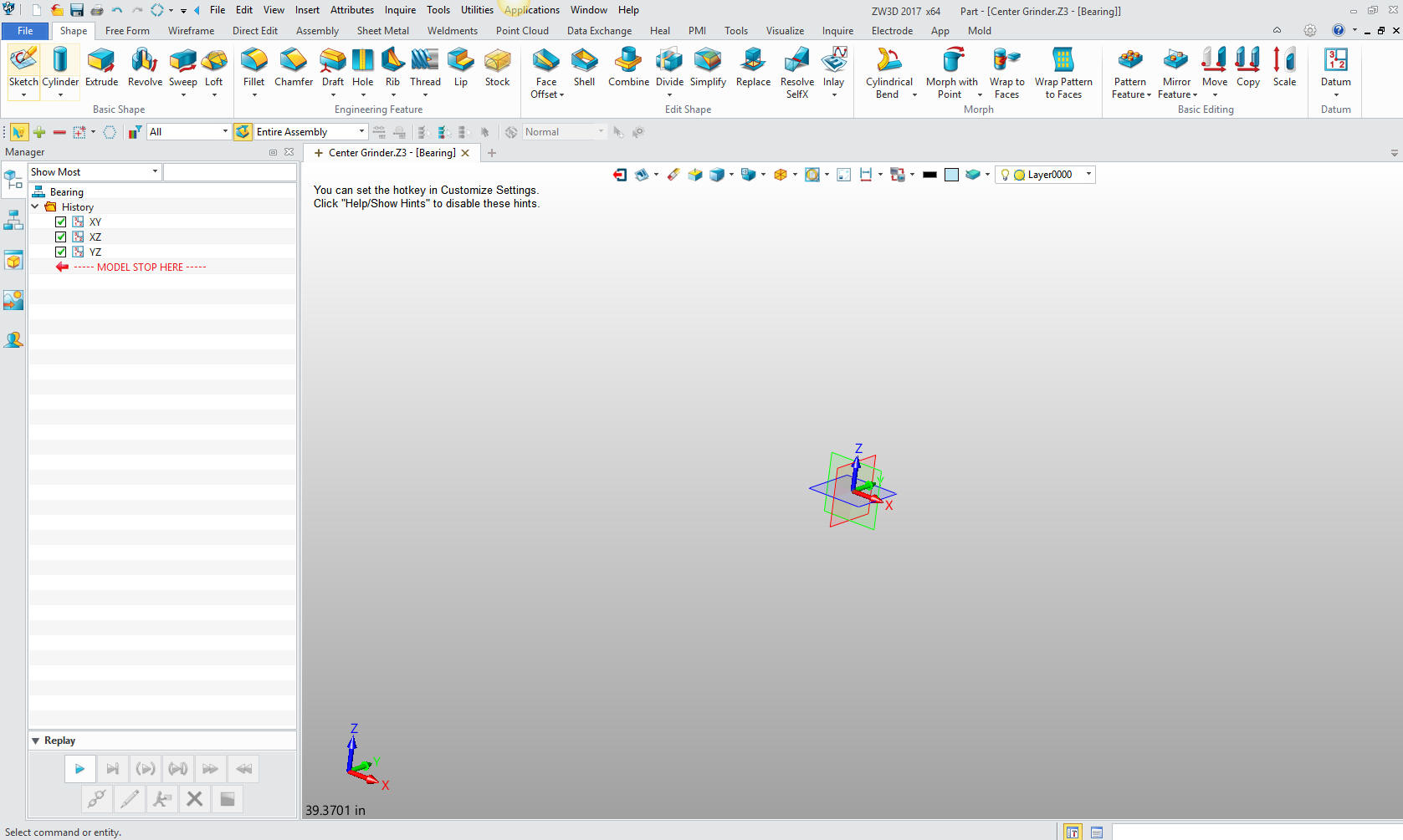
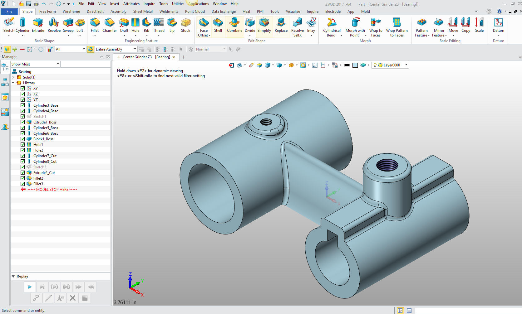
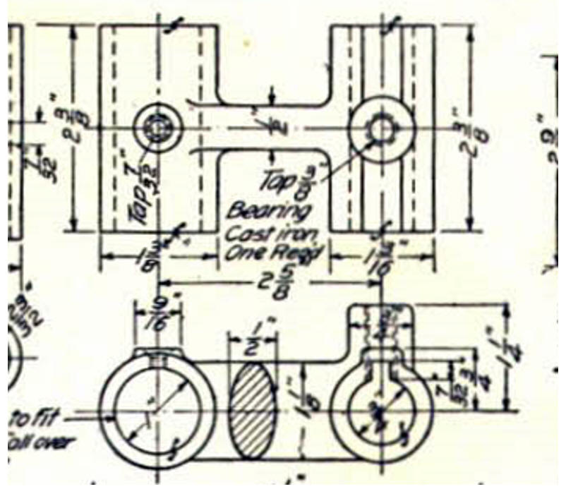
We will start with the Bearing.
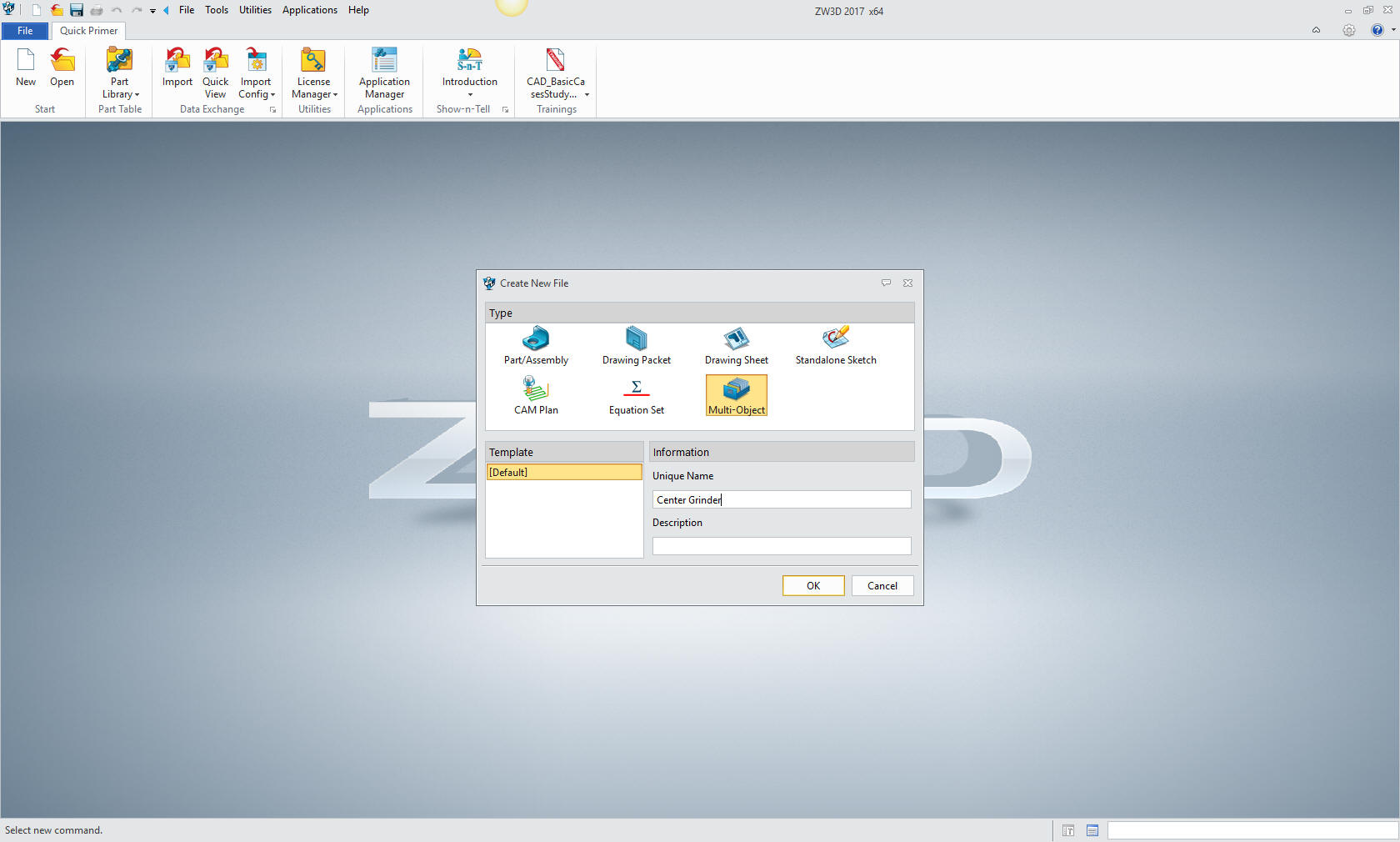
Even though you can have all of your parts and sub-assemblies in
one file, ZW3D is not a true single model environment. It offers
what they call the "Multi-Object" feature. We start by having a top
assembly and inserting components. We can insert as many as we like,
using them as place holders but in this case we will just add them as
we create each part. We will name this file: Center Grinder
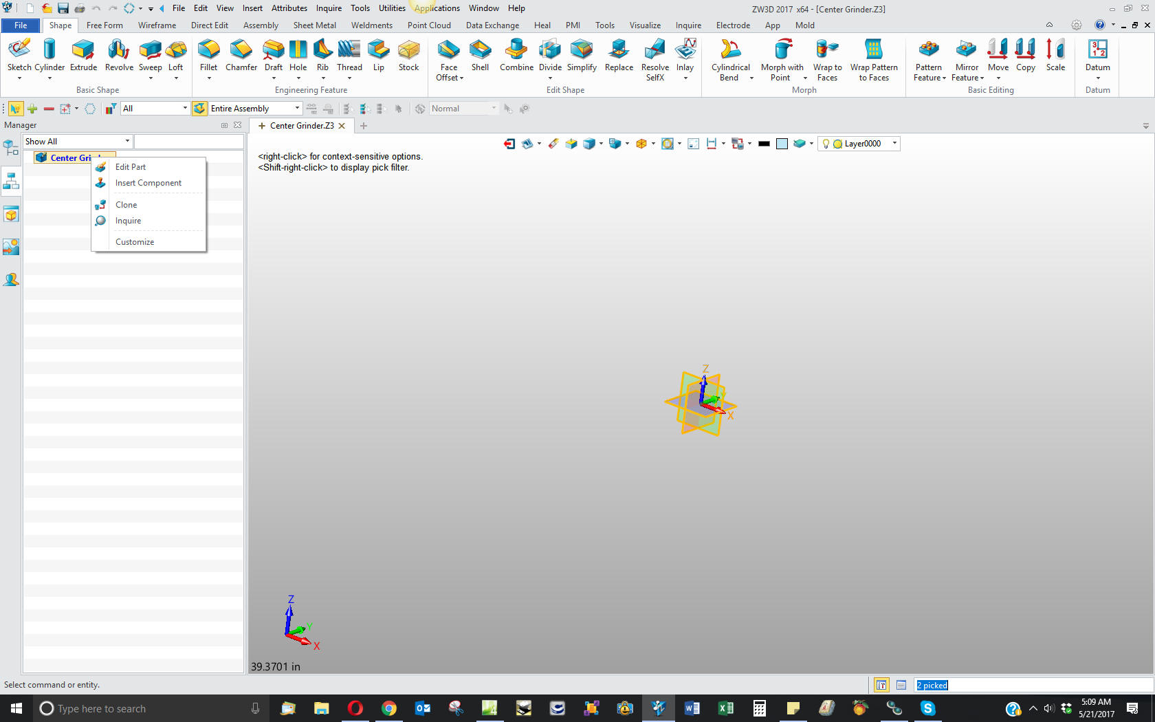
We will now insert
the top assembly. Notice the option for Multi-Object is now not
available.
We will
name this part Bearing.
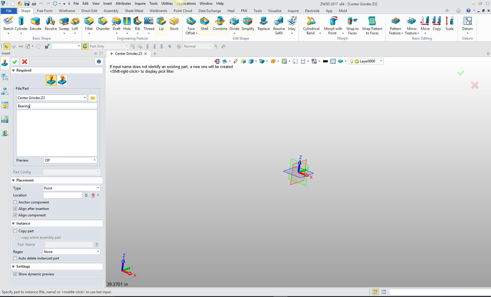
We
select the Bearing as the active part and we are ready to model
I
actually cut my solid modeling teeth on CADKEY and IronCAD where
both are single modeling environments. I was never confronted by the
option of using the X0YOZO planes. Planes were always an extra step
in the Pro/e clones and a bit of a mystery, since they were not a feature in CADKEY and IronCAD. Today, with
ZW3D I am getting used to them. I have decided to establish the
origin at the center of the ellipse.
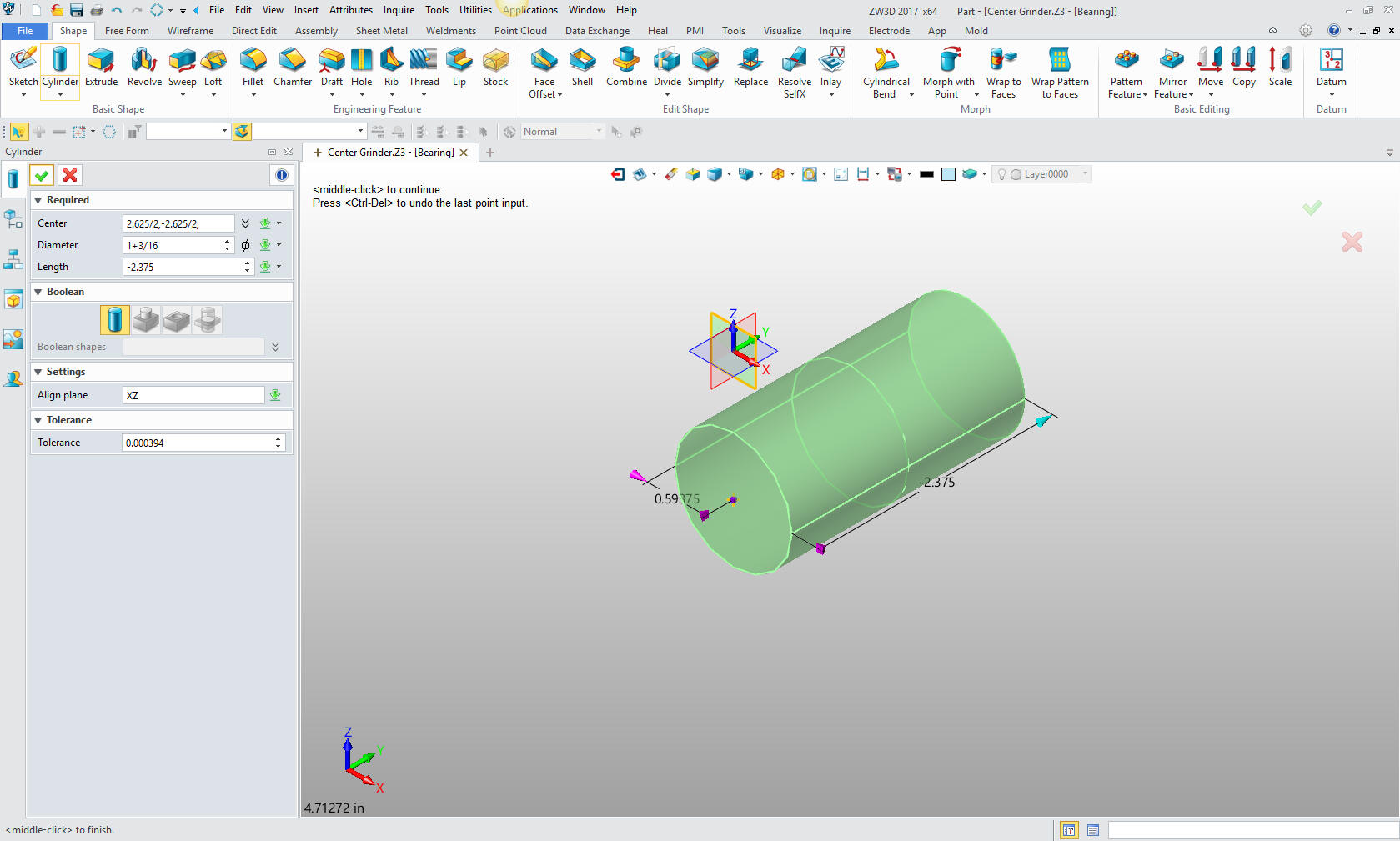
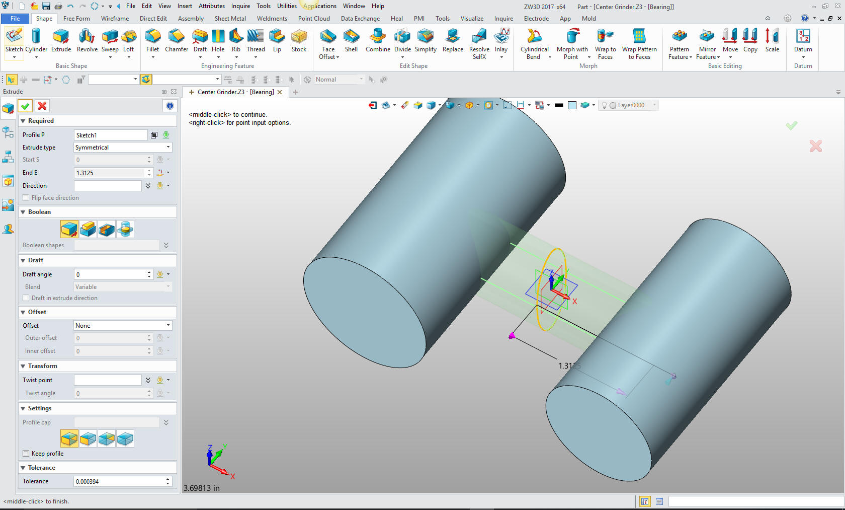
I create a primitive
cylinder by locating, aligning to a plane and sizing it.
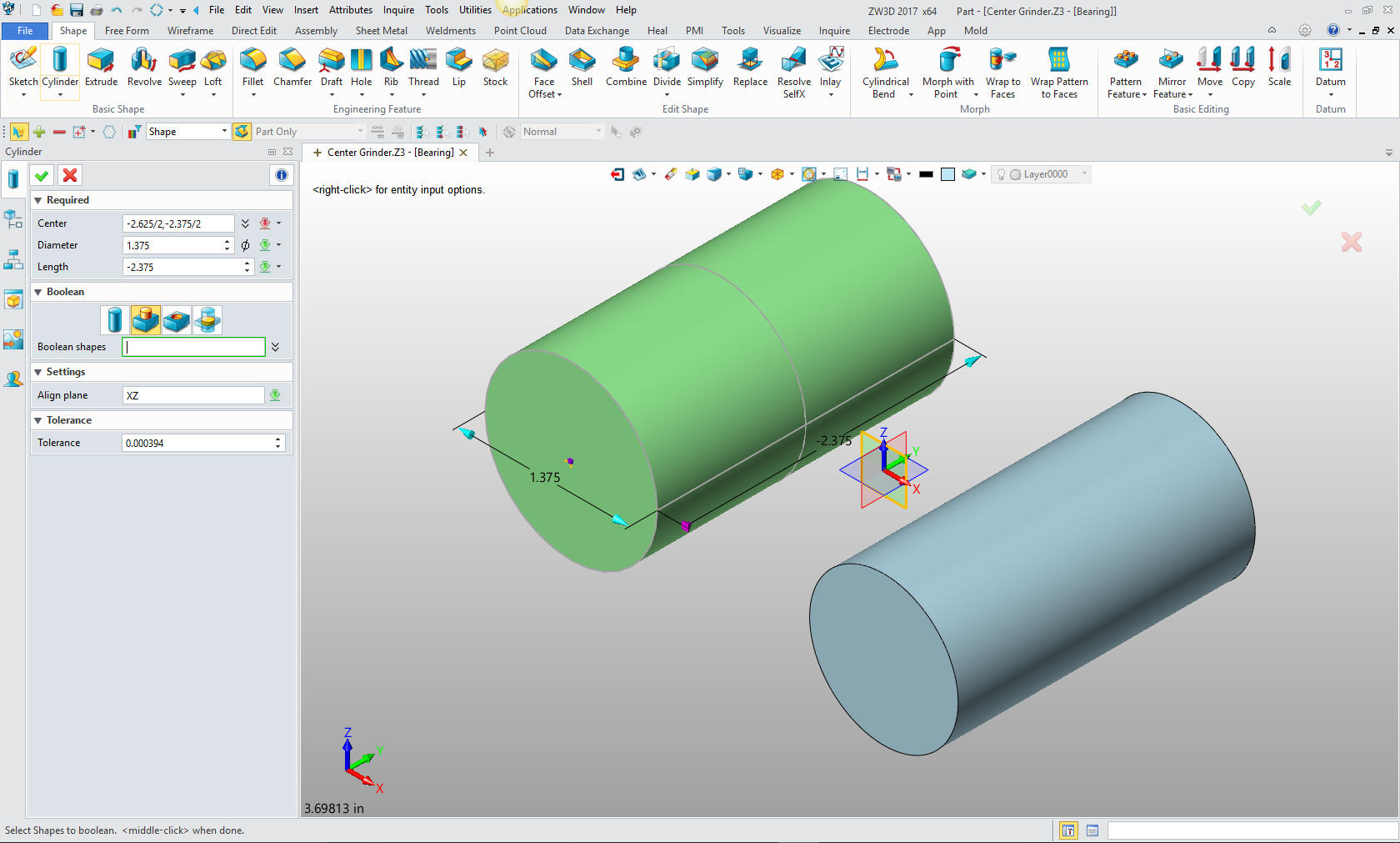
The
second cylinder is created the same way. This is done by inputting
the information in one dialog box. Very simple indeed. ZW3D allows
me to make this a component of the part even though it is not
connected. You can also have it a stand alone part in the same
workspace when creating an assembly with the option to move
each component to separate parts later.
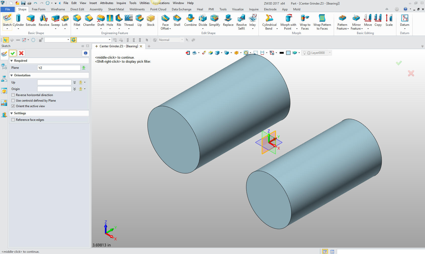
Now we
have to sketch the ellipse. There is no primitive shape available. We
insert a sketch on the YX plane.
We have a ellipse option, we place
it at X0Y0 size and we are done.
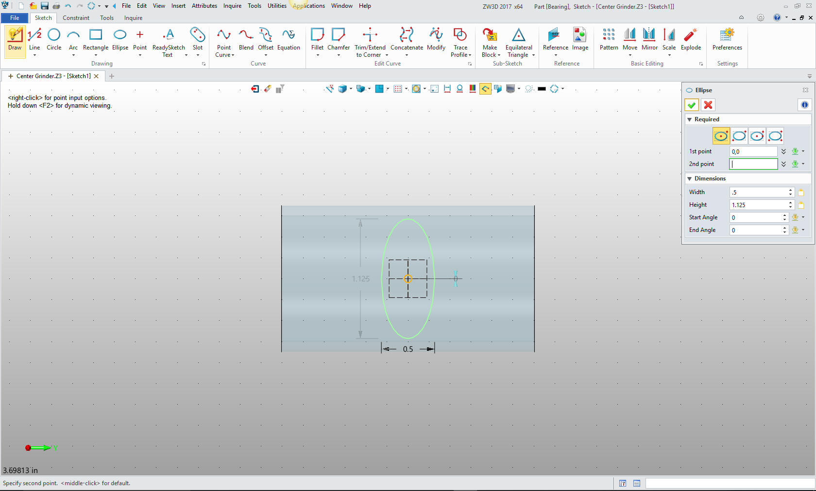
We set the extrude to symmetrical and
select the center of the cylinder as the location point.
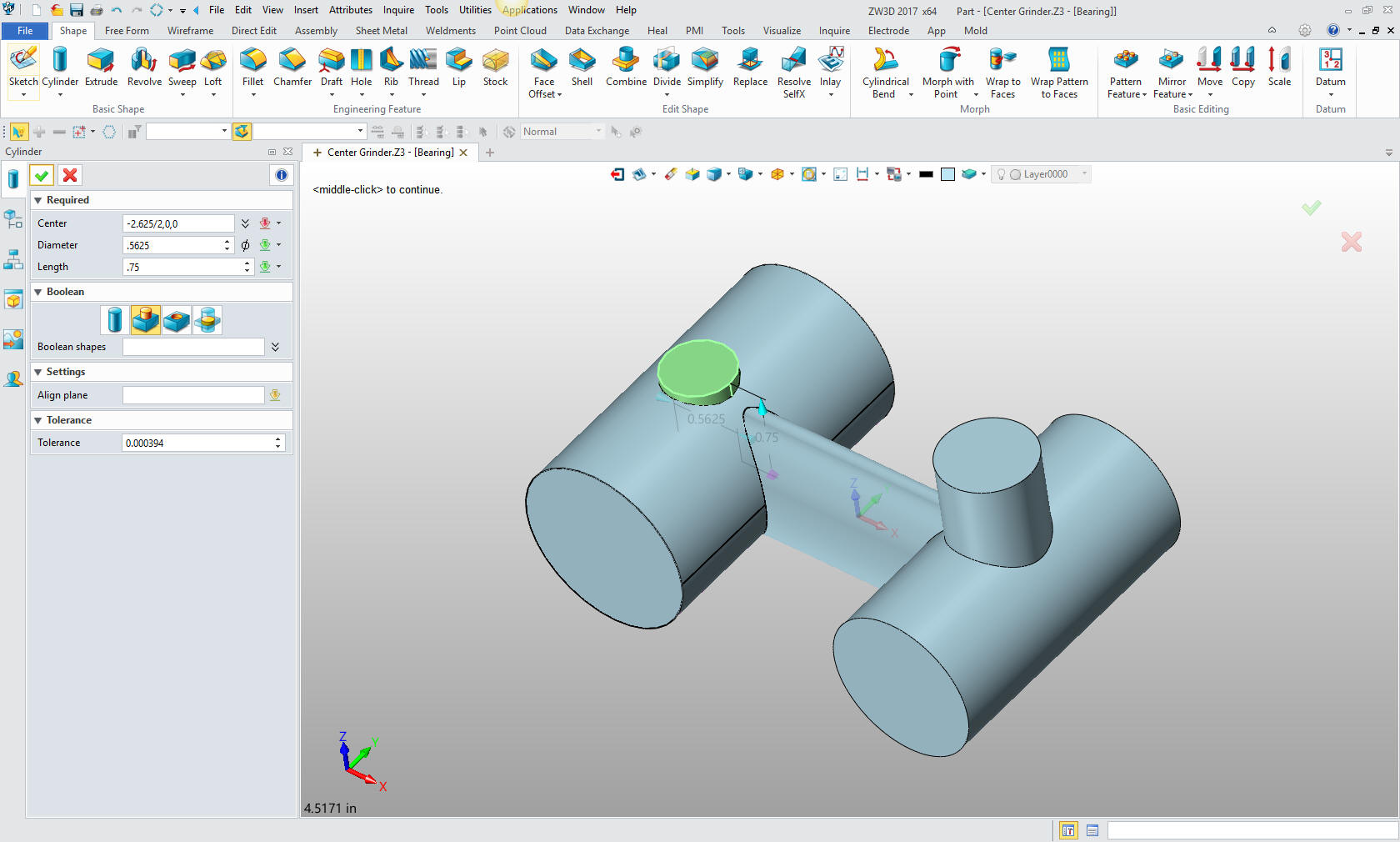
With that done we turn to the vertical
bosses. This is nothing more than inserting cylinders in the
appropriate locations and sizing them.
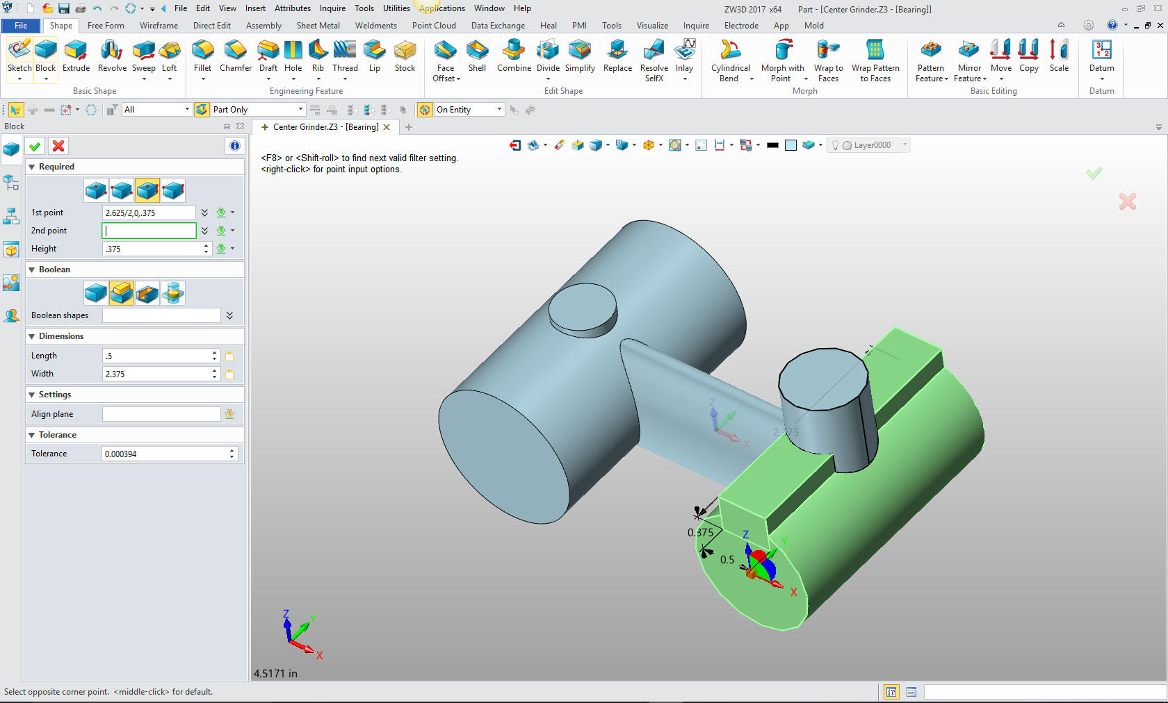
Now
for the block for the sliding key. We insert a block locate it and
size it.
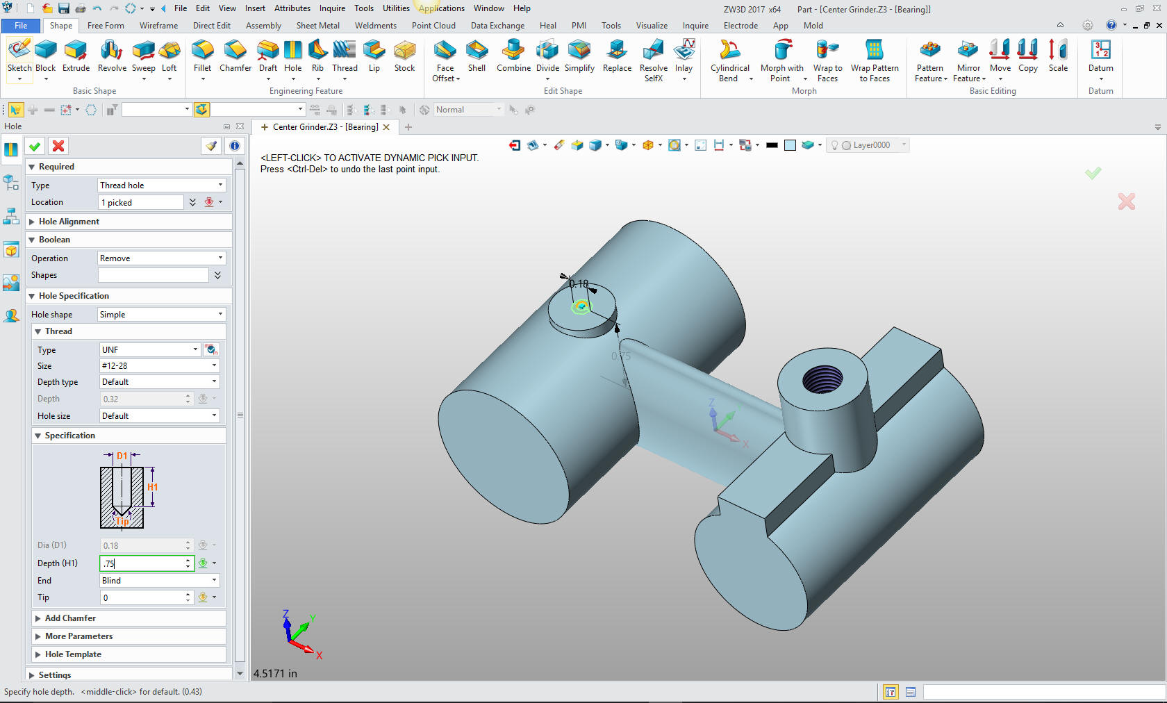
Now
for our threaded holes, we use the create hole feature. Again only
locating and defining the holes.
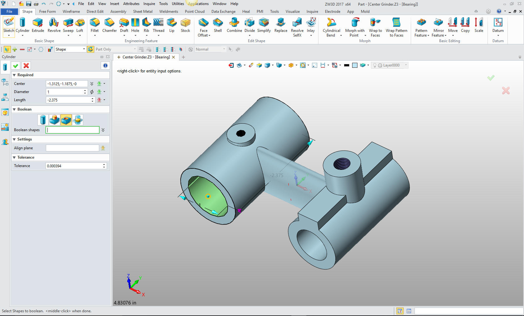
We
will create the holes with primitive cylinders again inserting a cylinder,
set it as subtract, locate and size.
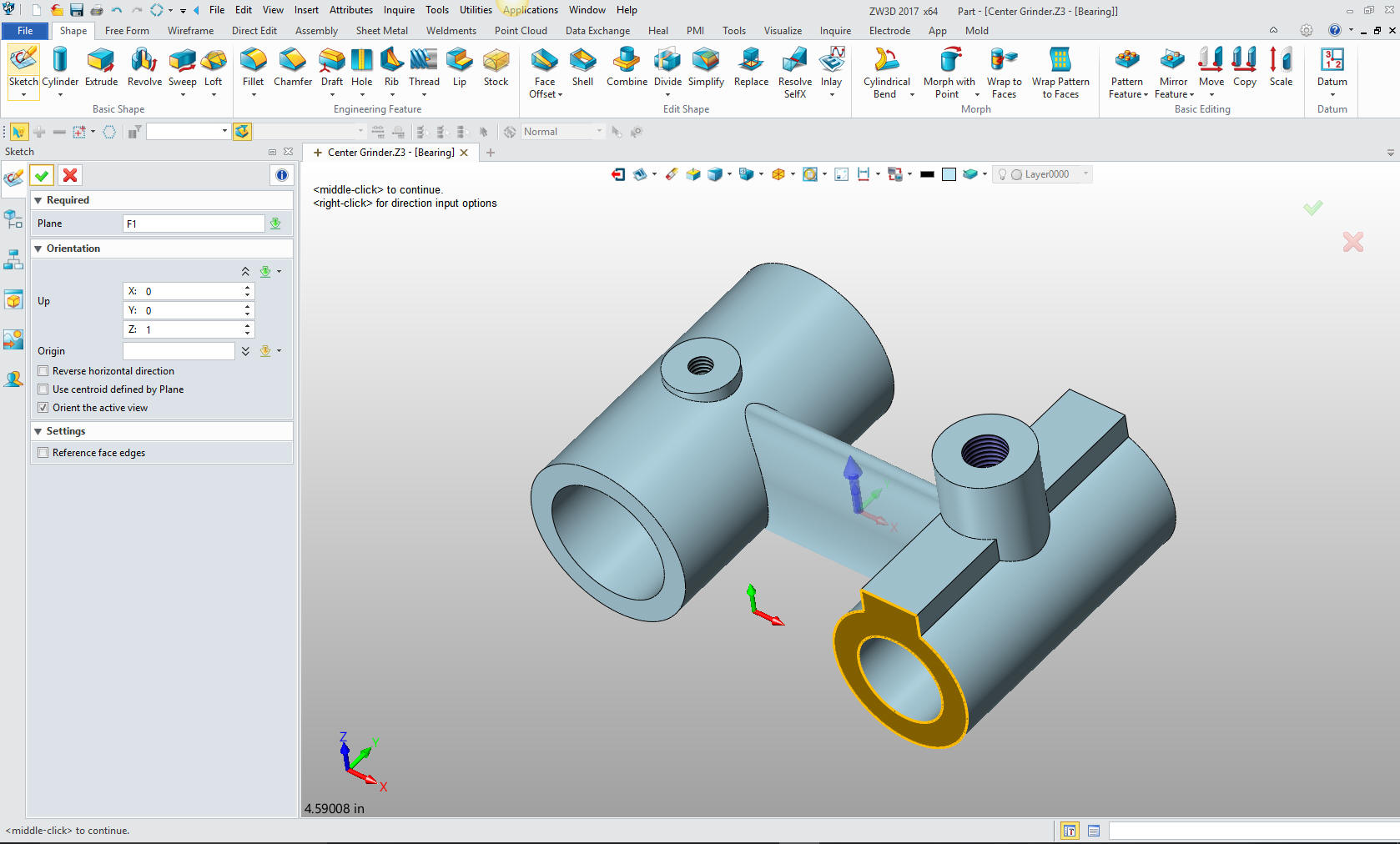
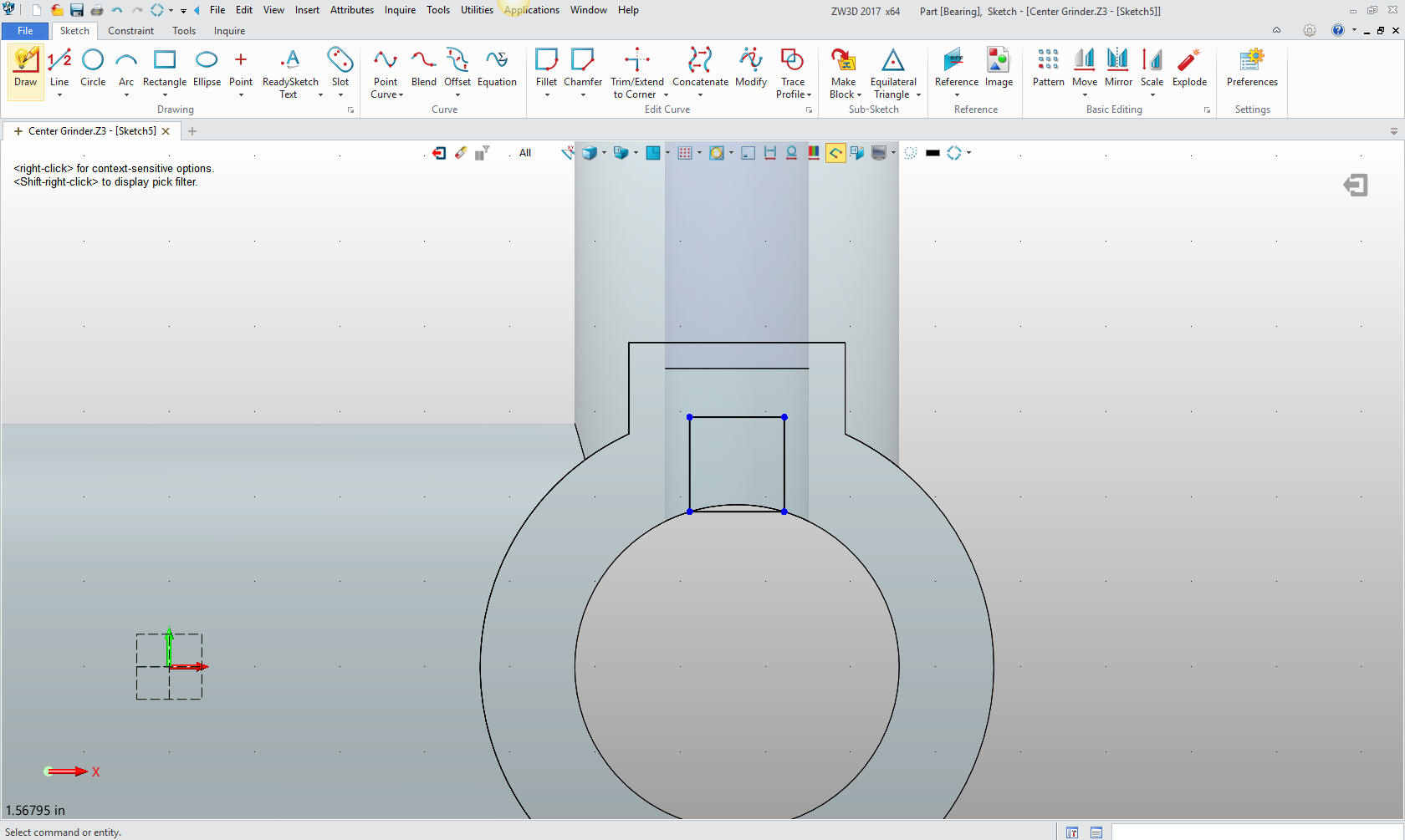
Now
the cut for the sliding key. We create sketching plane on the face
of the cylinder. We have the option to set the orientation of the
sketch. Up will be the Z axis.
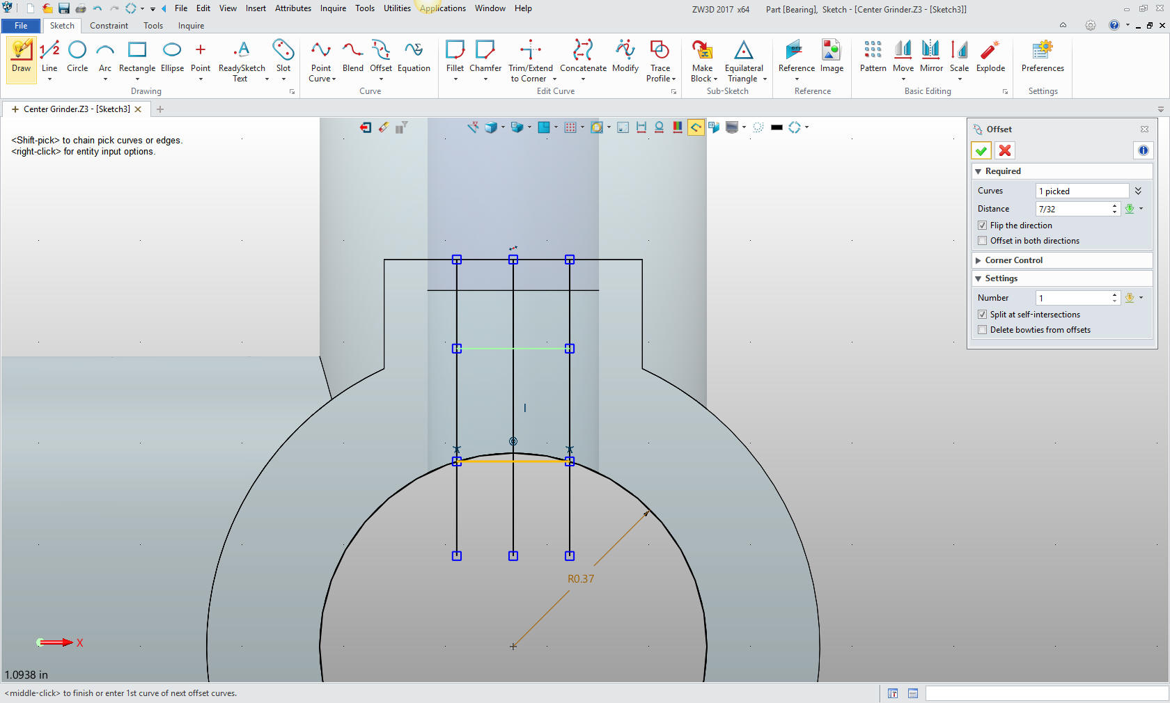
I just created a vertical centerline then offset the lines, I
created the horizontal line at the intersection of the lines and the
reference circle then offset the 7/32.
We
trim the lines and delete the entities we have used for construction.
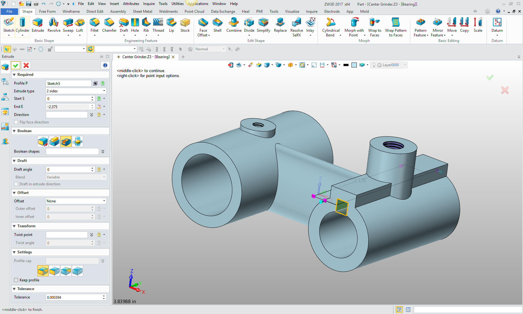
We
extrude the cut.
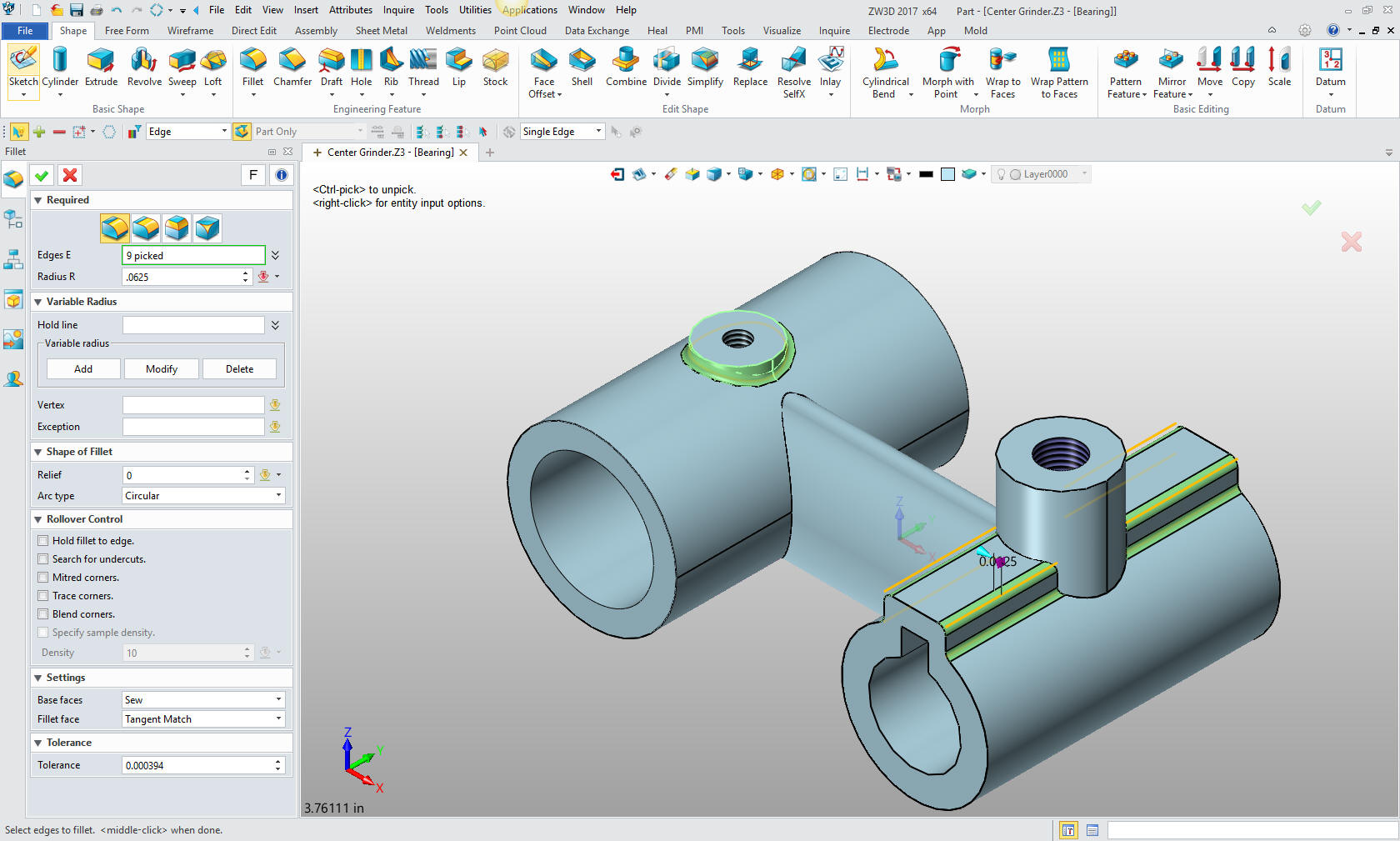
Now we
are ready for the fillets. Fillets should be put in last in most
cases and not put in haphazardly.
I have evaluated the requirements and have defined the basic fillets.
Fillets should be well thought through. Nothing makes someone look
like a CAD Jockey instead of a designer like badly defined fillets.
Now
the final fillets.
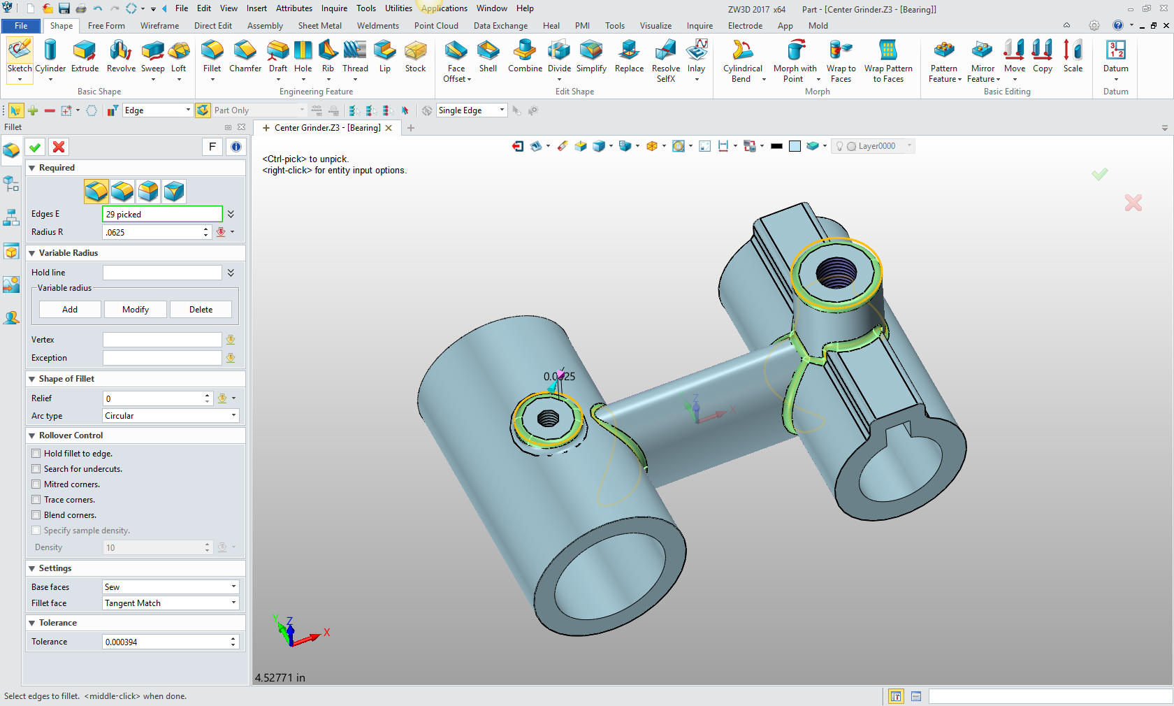
We are
done with the part. Yes, only two sketches. Primitive shape design
takes a lot of work out of modeling. Sketching only can be very tedious
and time consuming.
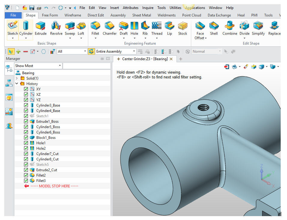
We
haven't talked about the history tree. Here are the step taken to
model this part.
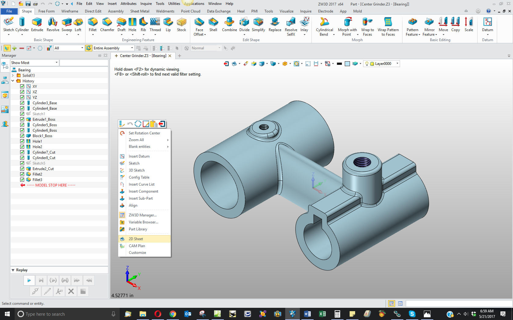
We
will now detail this part for clarity in case you would like to
follow along in your own system. ZW3D is one of the few 3D CAD
systems that has the documentation integrated in the part or
assembly file. You just right click in the workspace and select 2D
sheet. It is interesting that they didn't call it a drawing. Since
we are not going to draw anything I suppose it is appropriate.
Here
are the views defined in the 2D sheet. We add the dimensions and we
are completely done with the part.
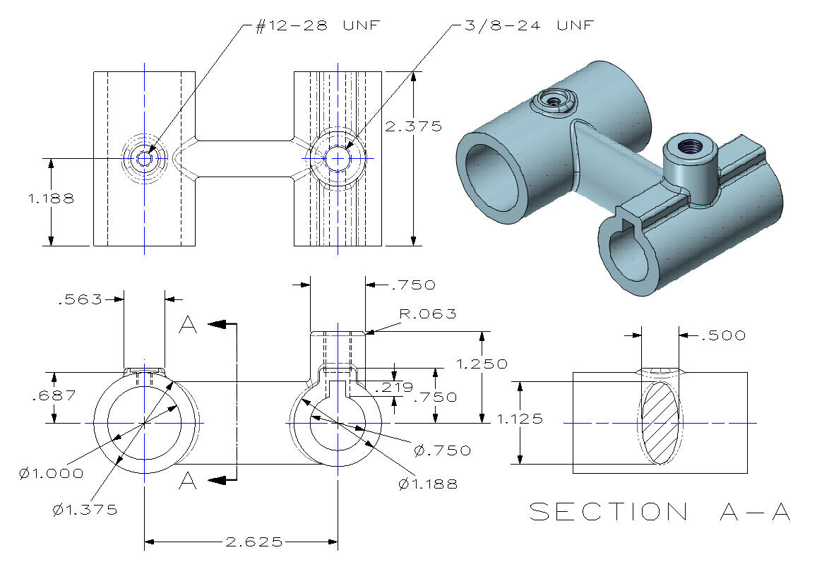
Here
is the original. I did add some dims that were not defined.
Now for lesson two:
3D Modeling Techniques ZW3D Lesson Two
If you would like
to try ZW3D, please download for a 30 day evaluation.
For more information or to download ZW3D
Give me a call if you have any
questions. I can set up a skype or go to meeting to show this part
or answer any of your questions on the operation of IronCAD. It
truly is the very best conceptual 3D CAD system.
TECH-NET Engineering Services!
We sell and
support IronCAD and ZW3D Products and
provide engineering
services throughout the USA and Canada!
Why TECH-NET Sells IronCAD and ZW3D
If you are interested in adding professional
hybrid modeling capabilities or looking for a new solution to
increase your productivity, take some time to download a fully
functional 30 day evaluation and play with these packages. Feel free
to give me a call if you have any questions or would like an on-line
presentation.
For more information or to download IronCAD or ZW3D
Joe Brouwer
206-842-0360
|