|
If you have a need for design and drafting services please give us a call! REVERSE ENGINEERING 2016 AK-47 PROJECT Making Scanned Data a Reality 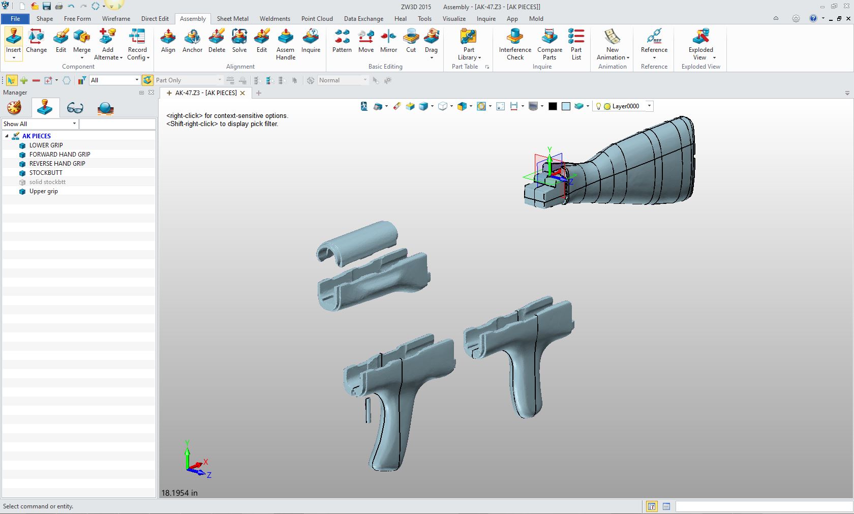 |
|
To truly understand a process you have to see it in action. You could read article after article about reverse engineering and walk away scratching your head. I hope this project shows you a bit of the process and what is necessary to easily get the job done. It all has to do with flexible hybrid 3D CAD tools, there is just no substitute. I got an email from an associate asking if I could help a fellow to reverse engineer the following parts. He was using CADKEY which does not have the capability of effectively working directly with raw scanned data. We were referred to ZI Outdoors LLC, who specialize in outdoor gear. They decided there was a definite market for US-manufactured AK-47 hand guards, replicas of those made in the 1970s and 1980s in Eastern Europe. They had the original parts and after talking to some CNC folks they were advised to get the parts scanned. They soon found that scanning parts was only the first step. The scans can only get you started in a process that is necessary to develop the scans into manufacturable 3D models. Here are the original parts. 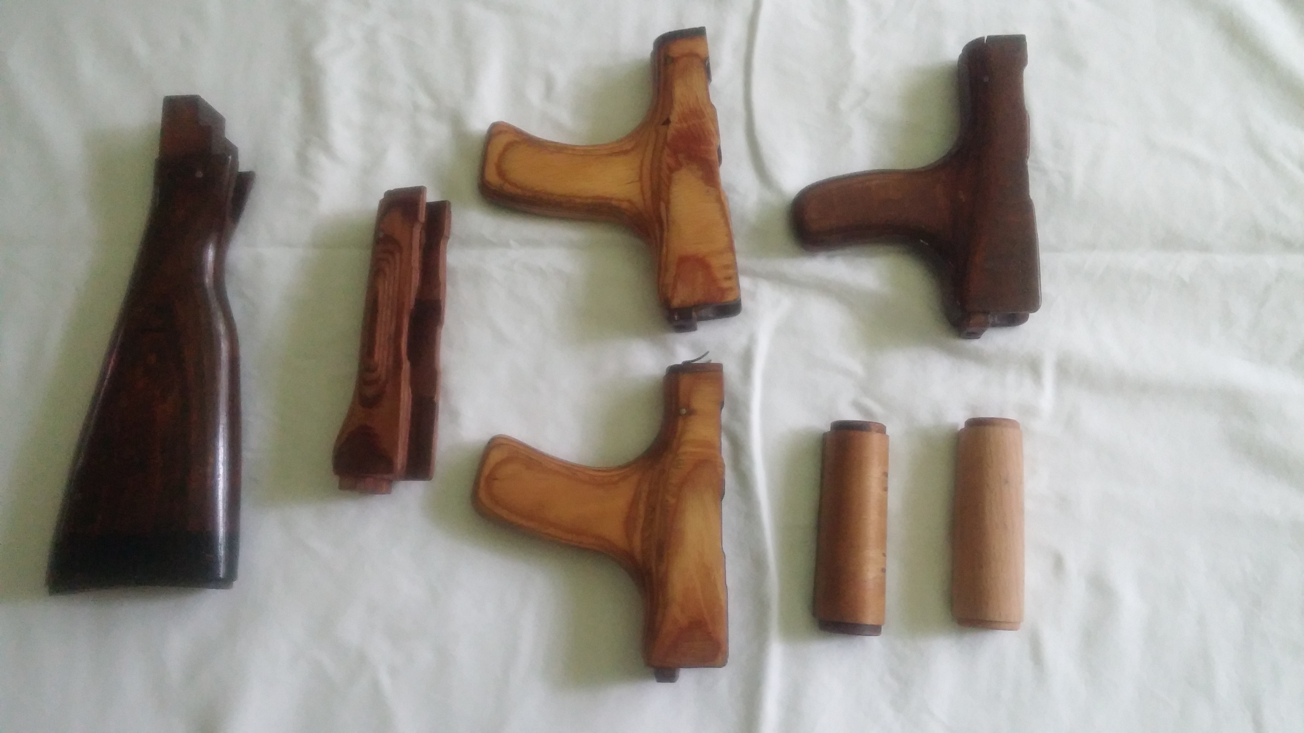 I had done a few reverse engineering projects in the past and I took a look at the job. It was the first time I took a serious look at solving this problem with the CAD products I use and sell. I first brought them into IronCAD that actually could make solids out of the stl files. I was quite surprise how well it worked, but I soon found it was a bit cumbersome since it seemed to slow the system down. I could trim the model and get the sections and generate the necessary curves to work with the basic shapes of the part. But I also knew that IronCAD's surfacing, like many CAD systems that include surfacing, can really only be used to enhance the solid modeling design not as a standalone surface modeler. I quickly realized that this would require a hybrid modeling system with wire frame, advanced surface design and solid modeling. To do reverse engineering from scanned data in the past I struggled to work the .stl files. I could do it with the tools I had but it was a lot of work. Here is one of my first jobs I did in 2011. I used an earlier version of ZW3D that could trim the .stl this was an incredible capability from struggling with other CAD systems. But just that function alone allowed me to easily complete the job. As you can see the full scan of the reveal. I trimmed it to a quarter and then started to work. I mirrored and copied, then joined and thickened the part into a functional solid. This was a test project I did for a job. I got the job. 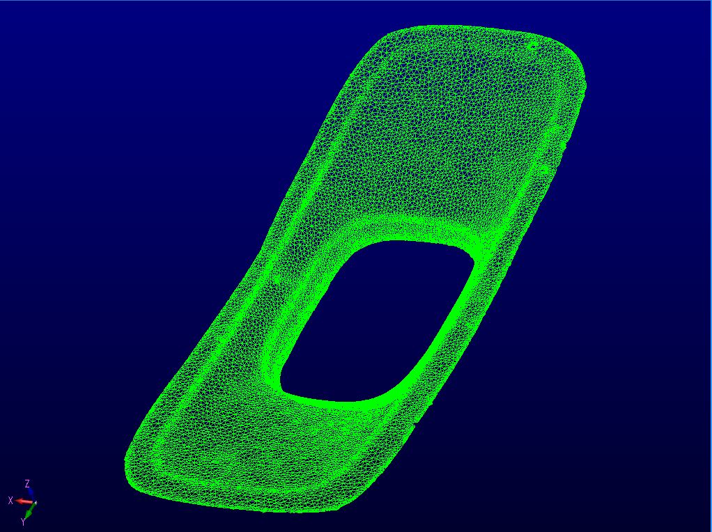 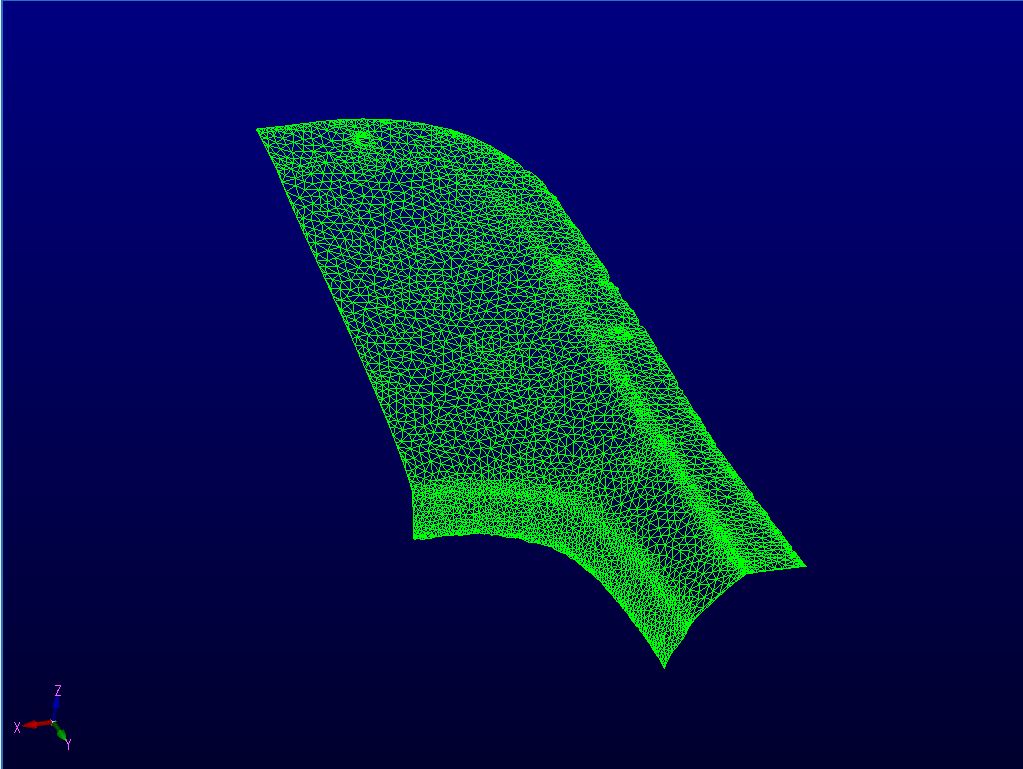 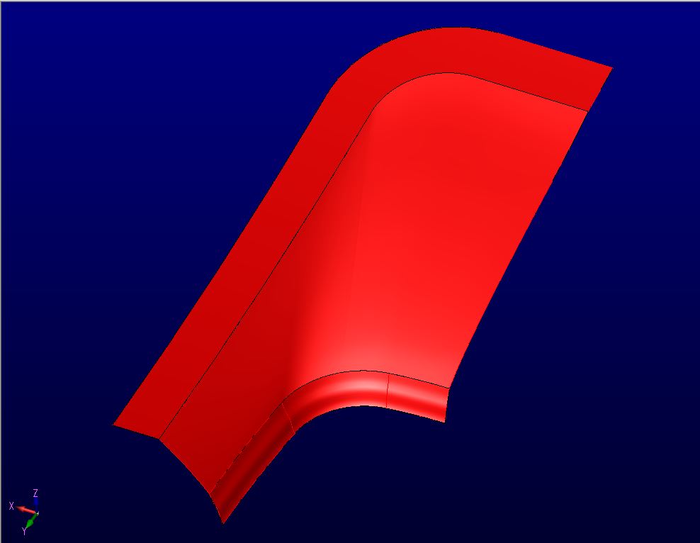 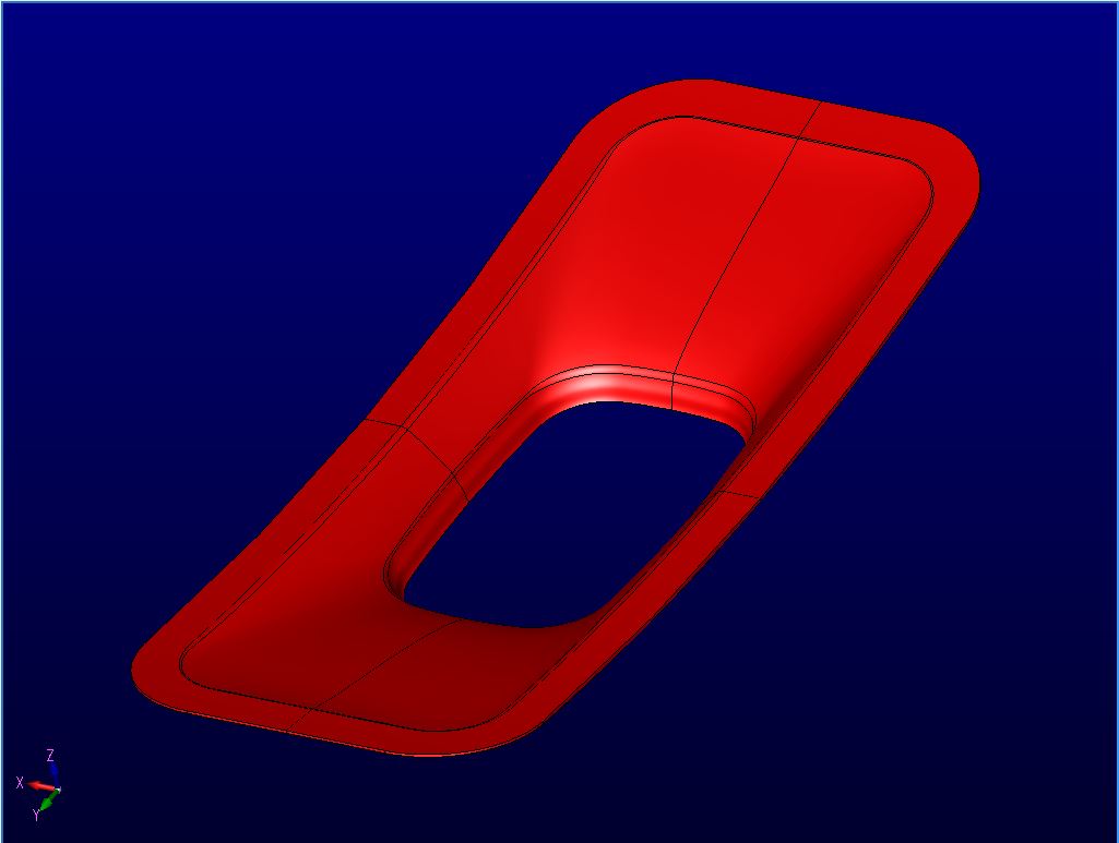 Below is a one button rendering out of IronCAD. 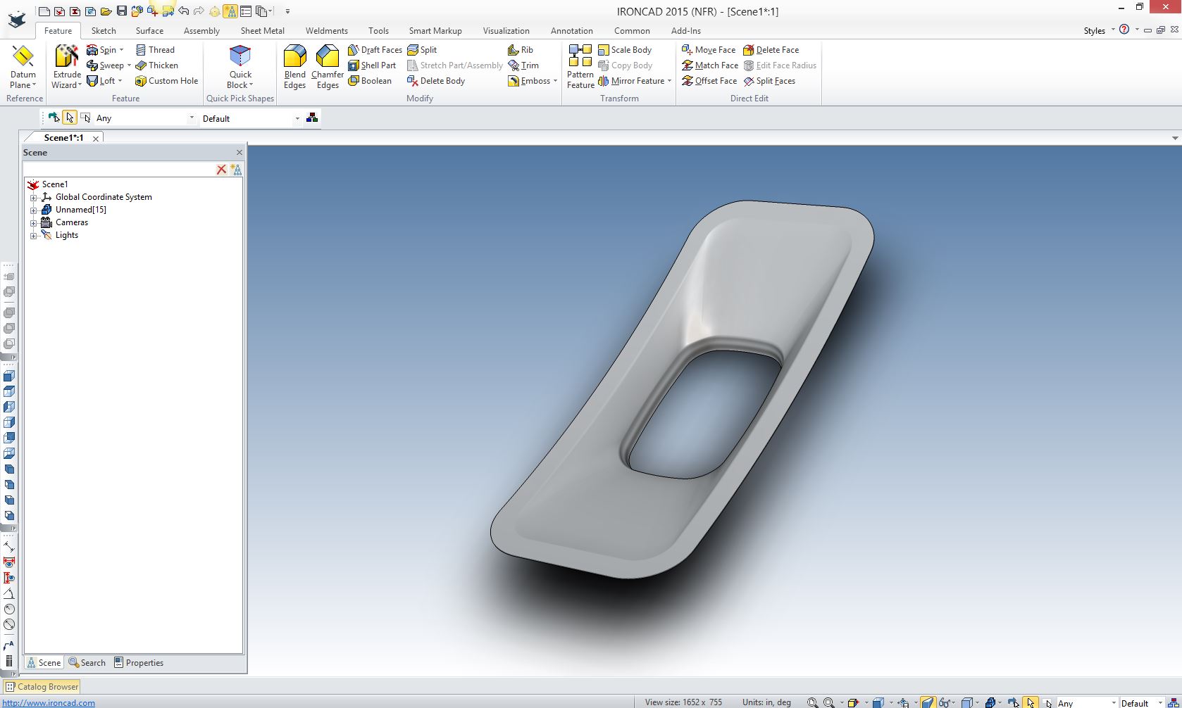 I moved to ZW3D 2015 and found that they had expanded their reverse engineering capabilities beyond what I could have ever have imagined. In the past I was fortunate enough to work with Rapidform, which I considered at the time, the very best program to work with stl files. It is really only designed to work with stl files at a price of $12,000. That price puts it outside the reach of the casual user. It was truly amazing how it would actually massage the mesh into a usable surface. But it was not a "CAD" program. While it had some rudimentary solid and surface modeling functionality it could not take the project to completion. I worked with a rapidform part in the reverse engineering of a 1959 Corvette bumper. The user gave me a refined file but it was nowhere close to being a functional model that could be delivered directly to manufacturing. It took much more work and we even had to go to an advanced surface modeler using Alias to complete the job, since the CAD software being used, all though having good surfacing, could just not do that last 5% that was required. REVERSE ENGINEERING SUCCESS! 1959 Corvette Bumper 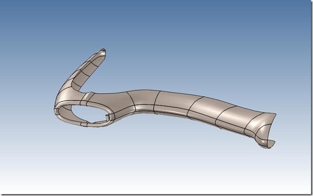 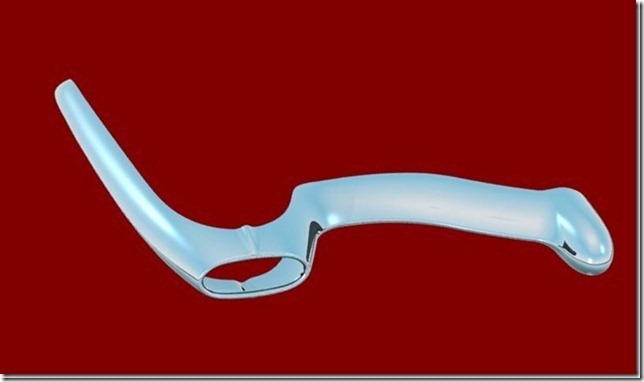
While reviewing the project, I took a look on the internet for drawings or 3D models of the AK-47 parts and found usable 3D models of the lower grip and upper cover. I found a few butt stocks, but they were nothing more than graphic cartoons or a different configuration. I could not find any drawings. Finding these parts cut the time for project in half to 16 hours. The existing parts required very little modification. Here are the original scanned parts. Like many reverse engineering or even normal CAD projects it can take hours of study to only have the final job take a couple of hours. The cuts were added by ZW3D. Here are the final parts, rendering was done in IronCAD 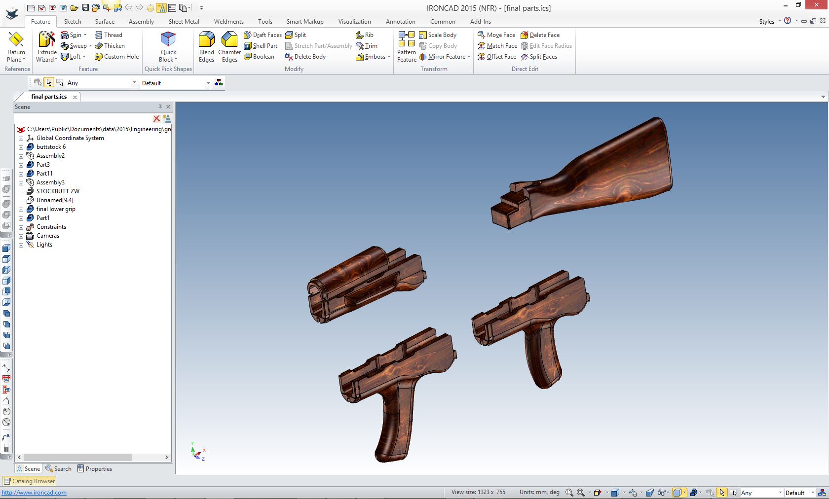 Let's take a look how this job was done. We will first focus on the butt stock since that was the most complicated shape. Here is the first preparation for the piece. I used "Trace Sharp Edge" and "Cross Section" for the center cut. 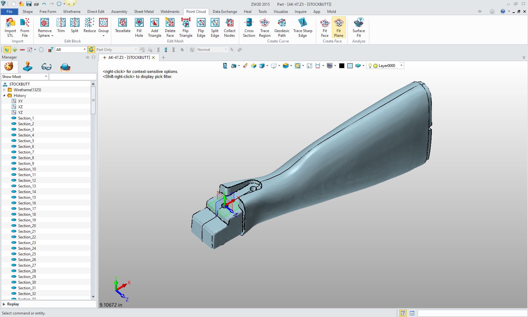 Here is the "Point Cloud" or Reverse Engineering menu showing the incredible functions that are now available in ZW3D 2015 Standard. It also includes Wirefame design and advanced Class A surfacing (Free Form) that are "absolutely required" for a fully functional reverse engineering system. All were used in this project. 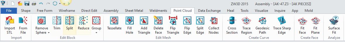 Here is a closer look at the menu. You can see it is well thought through and offers all the tools you will need to work with stl. Trim and split can be incredibly important. 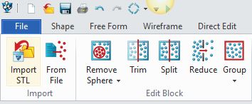 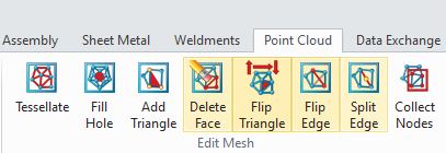 Below, were the most used tools. You can use fit face to create usable surfaces in certain situations. Many times just a few cross sections will be required. 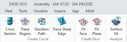 I had to develop wire frame curves generated from the section cuts of the stl to start the basic shape of the part. It consists of creating surfaces to start the part definition. As you can see below I turned the wire frame into arcs and lines since they are much easier to work with, then created the swept surfaces. 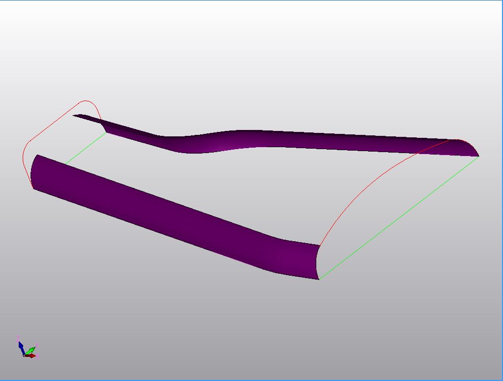 As you can see the fillets on the front of the part are smaller and I have to transition from the larger blends so I have to cut the surfaces at a somewhat arbitrary location. This can take a bit of trial and error. 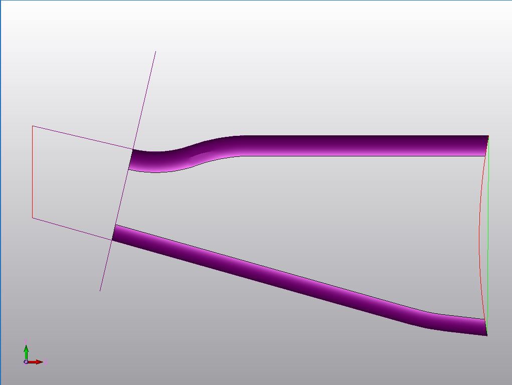 After that is solved, we have to create the complete wire frame using a blend spline command and curve from edge. The blue lines were created to tangently connect the inner splines. We have now created a wire frame that will be used to create a surface with the "Mesh Surface Command". The green lines are not used. 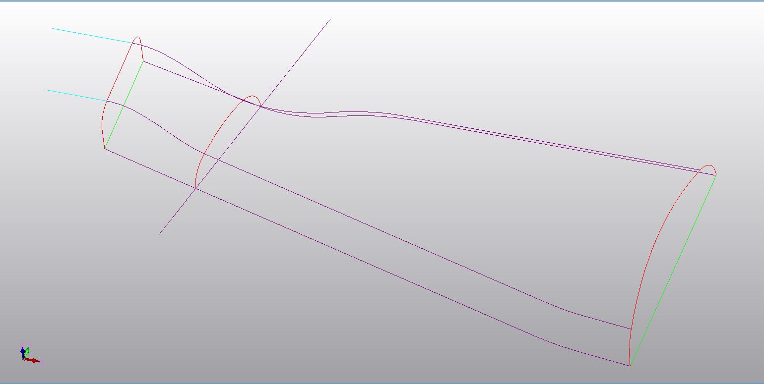 Here is the finished surface. 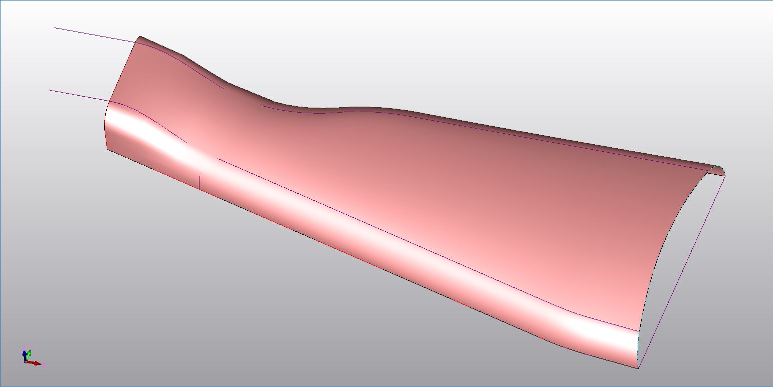 We mirror the surface, add the end faces and healed it into a solid. We have also brought the previously prepared front shape in as separate part. 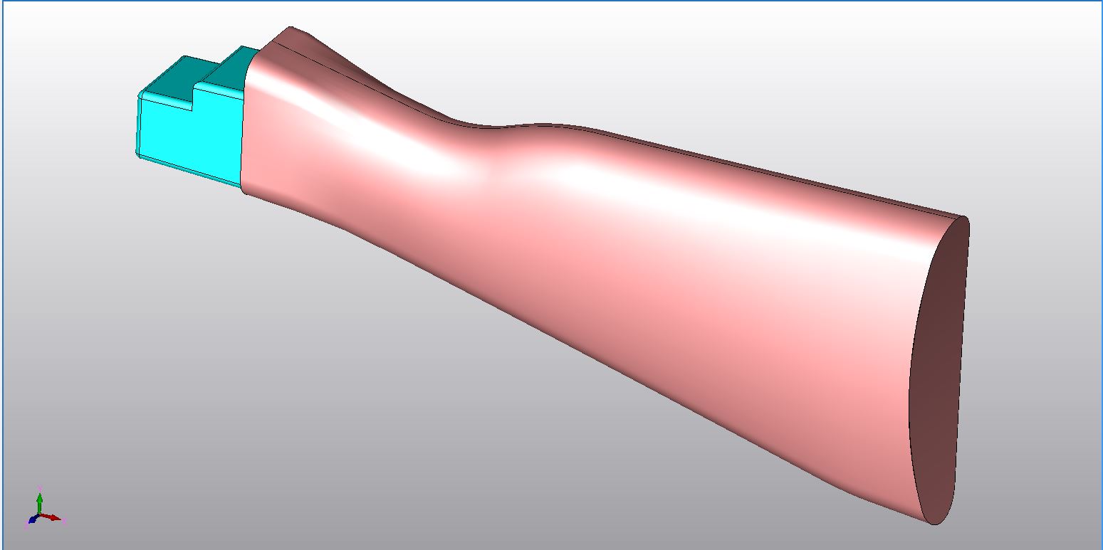 We Boolean union the front shape and the stock into a solid. Now we can add the other features with much easier to use solid modeling tools. Sometimes it is easier to create a positive part and Boolean subtract it than struggling to design it inside the existing part. Here is the cavity in the back of the stock before subtracting it. 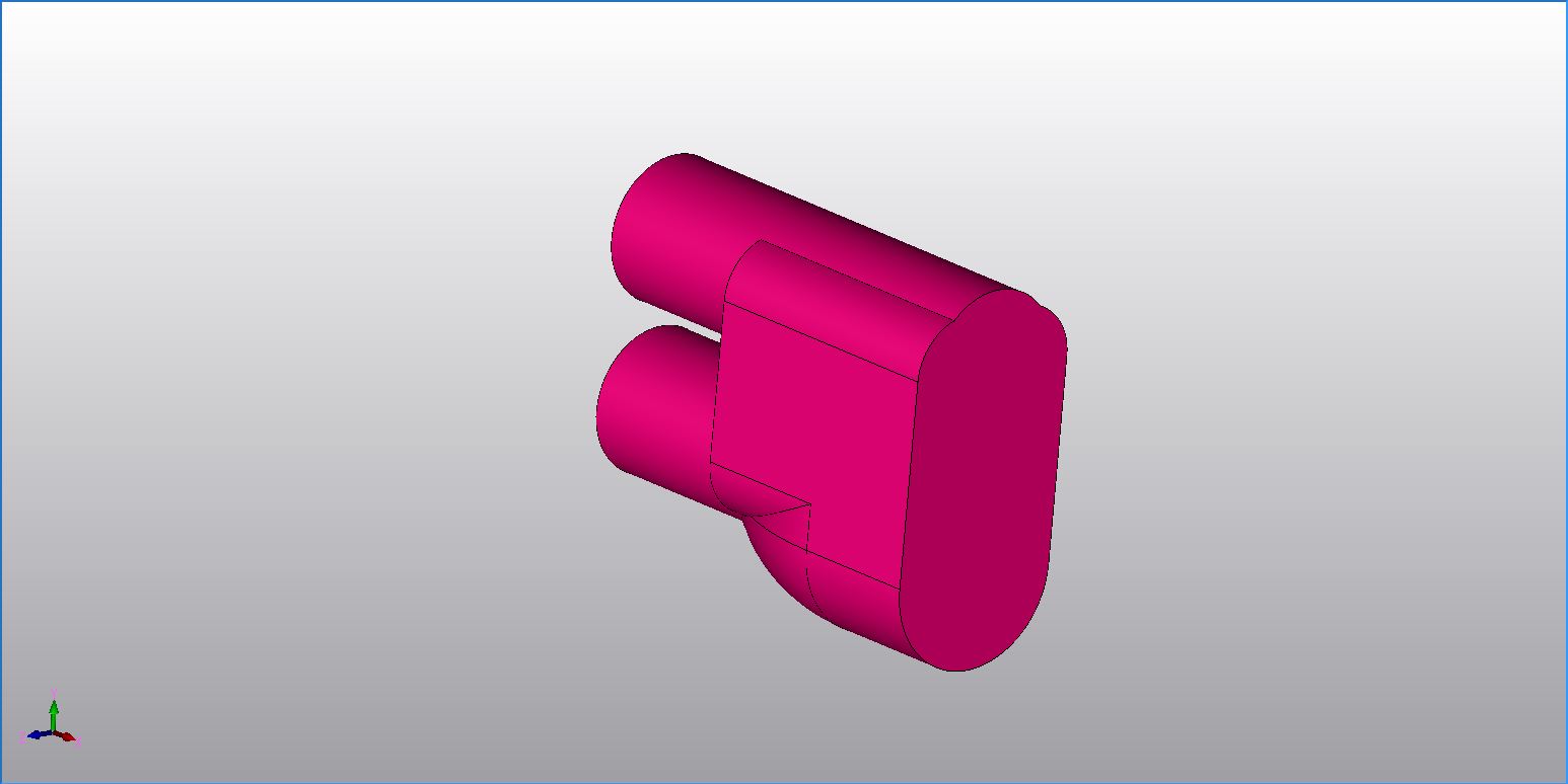 Here is the completed part. As you can see to do reverse engineering from scans you have to have a hybrid modeling system where wireframe, surfaces and solids can coexist and be easily be utilized. There is just no substitute. ZW3D Standard is that product, it surpasses the closest competitor at thousands less, only $3,000.00 and a 6 month rental of $650.00 and 12 month rental of $1200.00 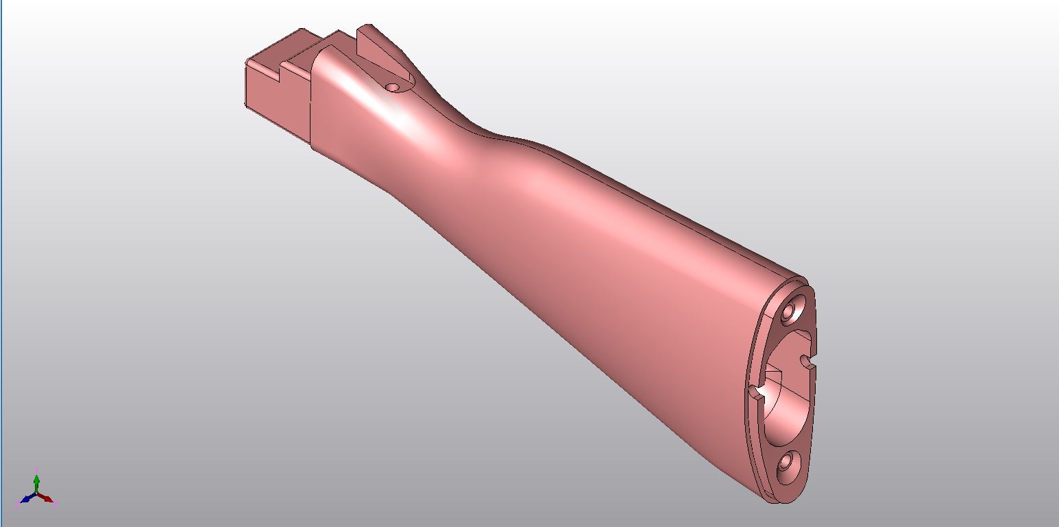 Let's continue with the design of the other parts. Here are the original scans with the two required cuts. 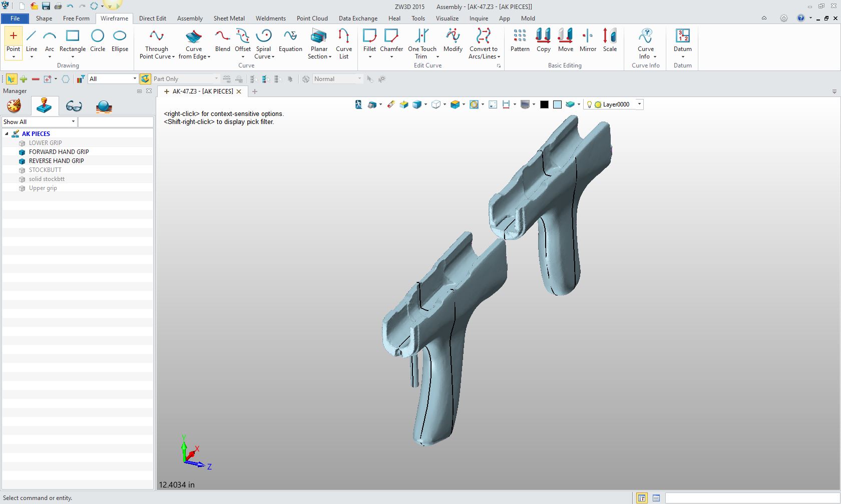 This was going to be a bit different process since we had an existing solid model. Here are the original parts downloaded from the internet. Both were created by the same fellow in Eastern Europe, the upper cover in a native Inventor file and the lower grip in a STEP file. Neither file needed any modifications. 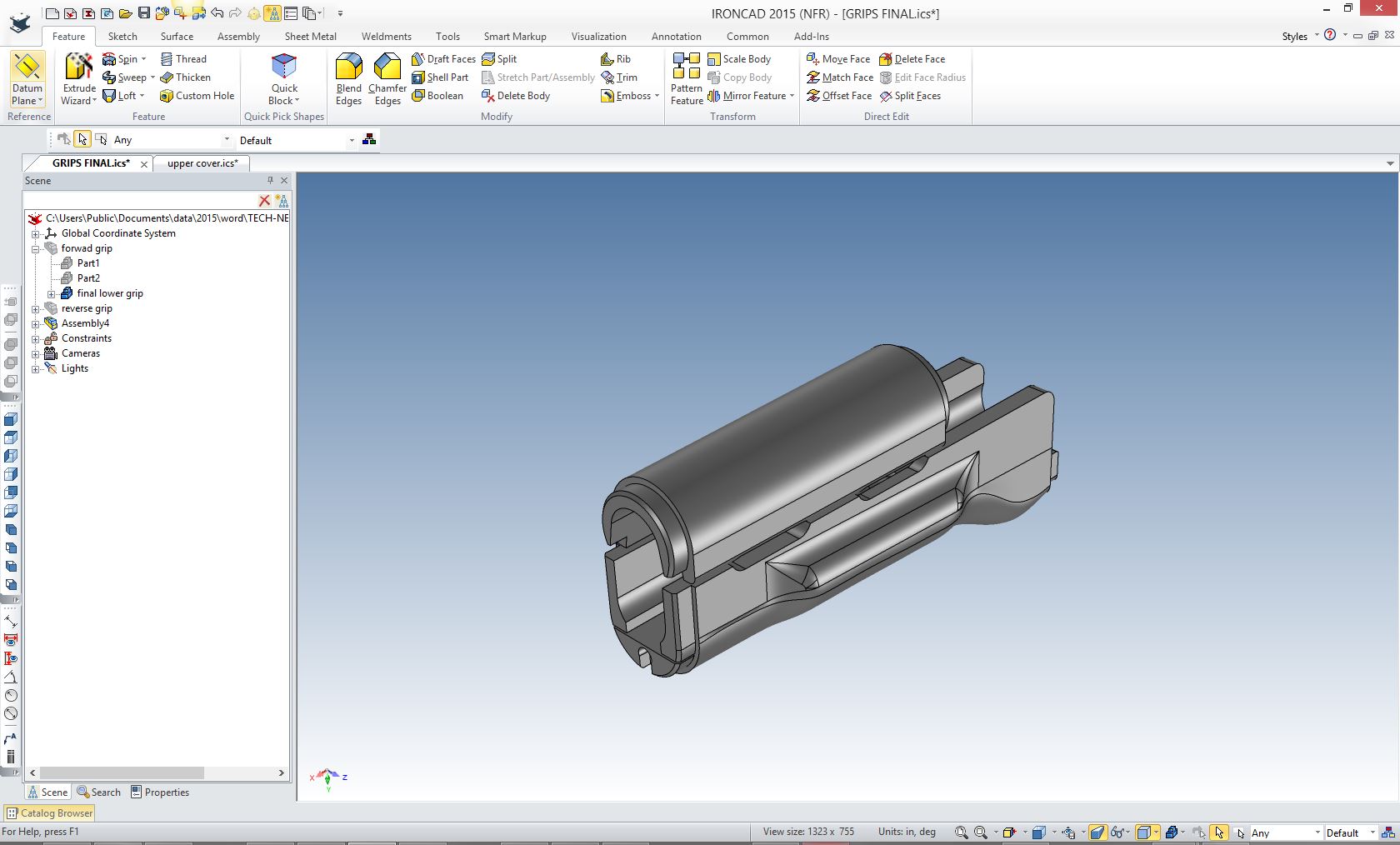 The existing lower grip had to be modified to add the handles. As you can see below it was a bit of work. The biggest problem was the variable blend or fillet. I only had to create half of the part. 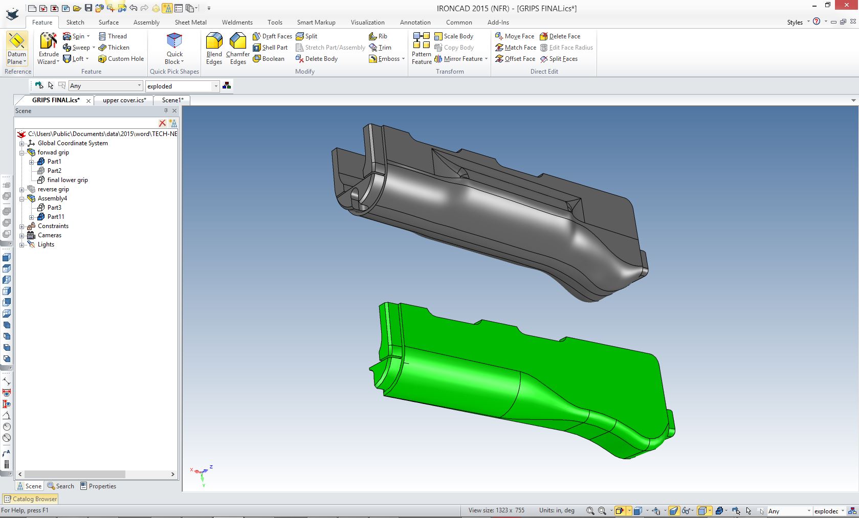 After I finished with modifying the lower grip in both IronCAD and ZW3D I moved the job to IronCAD to finish it up. IronCAD is a bit easier to work with solids (I moved back and forth, as the design required). Here is one of the handles defined in IronCAD. It includes the curves generated in ZW3D with the cross section command, the basic sketch generated from the curves and the finished solid handle with blends. 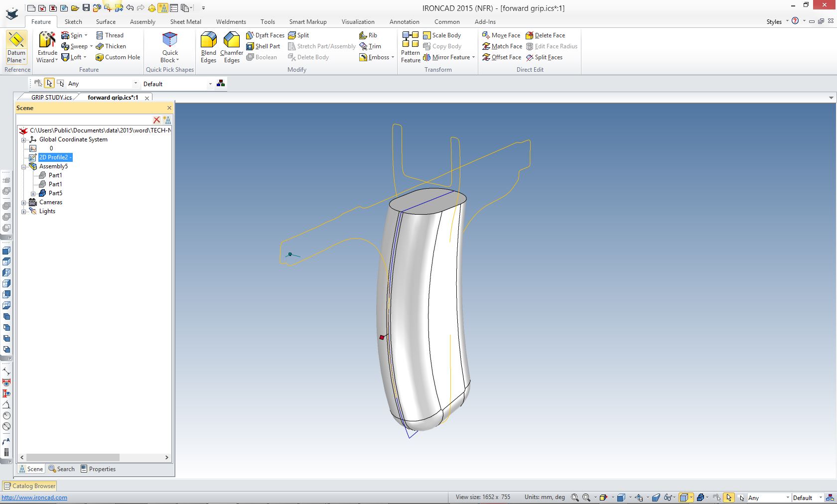 Here are the lower grips and handles before we Booleaned them into a solid and added the blend. 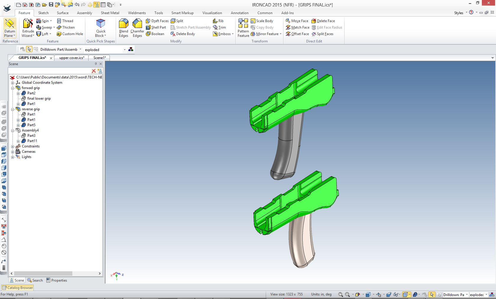 Here are the final pieces with texture added ready to be sent to the manufacturer. 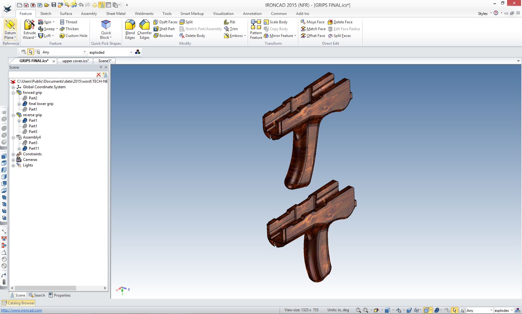 As you can see the job is done. I spent a little more time studying the process and exploring the new reverse engineering functionality in ZW3D Standard. Just think of the tools you would have to have with your current software or even if you could to do it at all. But not all reverse engineering comes from 3D scans. Here is a project I did a few years ago. We used scanned drawings converted to .dxf and used the graphics directly. It was amazing how precise the scan was. Take a look how this was done. THE SEATTLE MONORAIL CRASH! A Study in Murphy's Law and Reverse Engineering! 
  ZW3D is probably the most "complete" hybrid modeler available matching or surpassing CAD systems no matter what the cost. Incredibly the price does not reflect that at $3,000.00. It also has all of the standard solid modeling functionality with both history and integrated direct editing, sheet metal design and integrated documentation capability (drawings). It is the only history based system that can do complete projects in one file with the multi-object option making it, in my opinion, the ultimate CAD system. Then you add integrated mold design and associated CNC you have the most complete CAD/CAM system. The Ultimate CAD System Learning Mechanical CAD And now for IronCAD. It is by far the best conceptual design CAD system. I used both ZW3D and IronCAD in this design process. IronCAD has a modeling only package called Inovate that allows you to add IronCAD's fast and fun drag and drop design paradigm to your engineering arsenal at a very reasonable cost. It also includes realistic rendering and animation. Both of our programs are single model environments. Five Functions that Increase CAD Productivity!! IronCAD vs Solidworks and the Pro/e Paradigm Simplifying Your Design Process! ZW3D Pricing
We sell and support IronCAD
and ZW3D Products and
provide engineering services throughout the USA and Canada! If you are interested in adding professional hybrid modeling capabilities or looking for a new solution to increase your productivity, take some time to download a fully functional 30 day evaluation and play with these packages. Feel free to give me a call if you have any questions or would like an on-line presentation. For more information or to download IronCAD or ZW3D Here Joe Brouwer 206-842-0360 |
TECH-NET ASSOCIATES | RENDERING OF THE MONTH | CAD•CAM SERVICES
HARDWARE | TECH TIPS | EMPLOYMENT | CONTACT