3D Modeling Techniques Defined IRONCAD vs Fusion 360 Lesson 11 Streamlined Sketching Exposed Two
An
Exercise in Sketching Two
I will do this part as I would have
done it on the drafting board. Basically offsetting lines. This is
the basis for what I have coined "Streamlined Sketching".
I
have to admit the Fusion 360 presenter makes this simple sketch
incredibly convoluted. Make sure you watch the Video. If you are
sketching this way you are wasting an incredible amount of time.
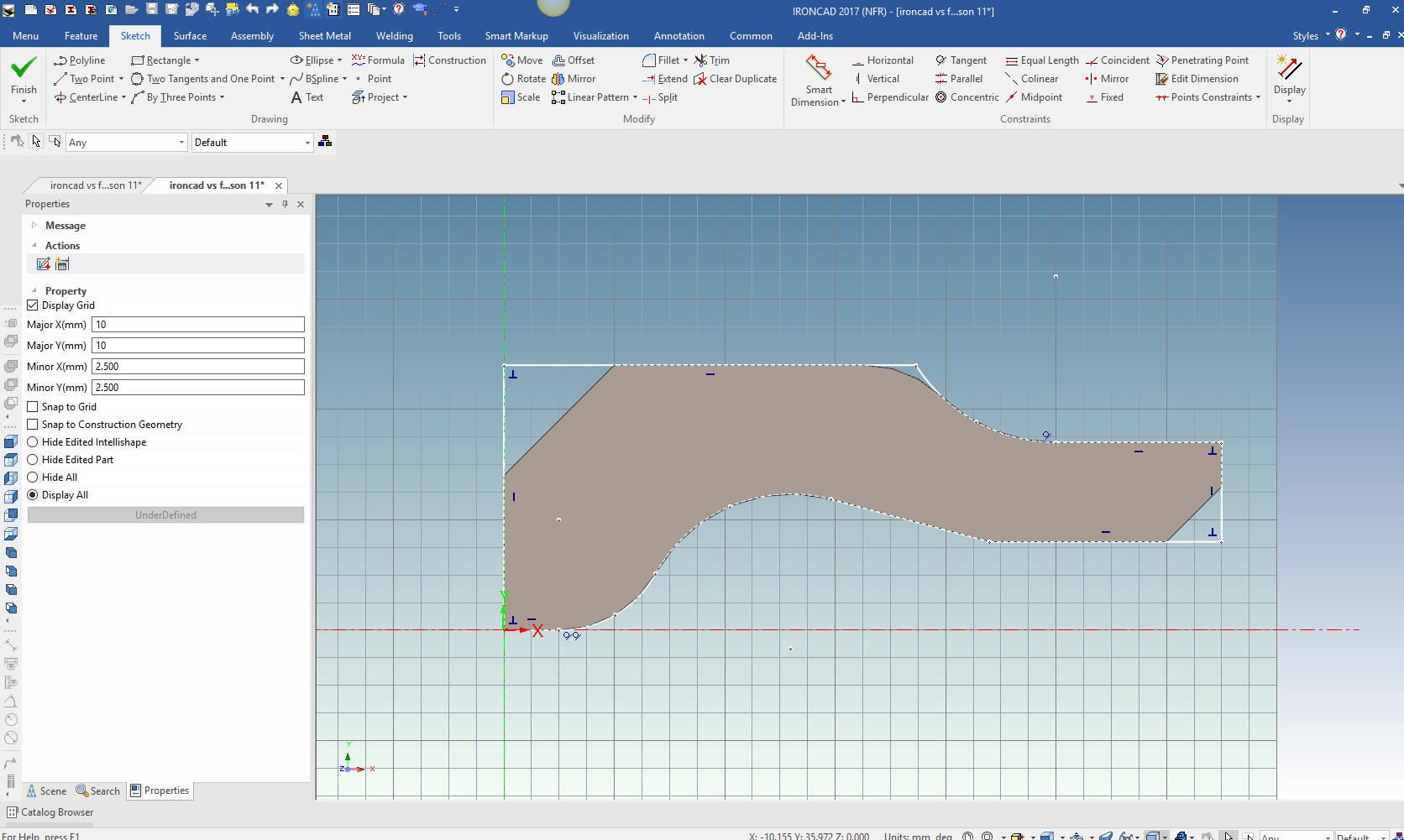
You can see in the above sketch
there are no dimensions?
How can this be? Let me show you. I have done quite a few
comparisons with all of the 3D CAD systems and I have found in all the presentations an extremely
complex sketching process.
Sketching has always been a
secondary process in my design.
With IronCAD most of your
design is dragging and dropping what are called IntelliShapes in the
scene and pulling and pushing them together into a shape. We have a
Extrude Wizard that allows you to project edges for a new feature or
part. So my sketching has never utilized constraints, even though
they are available.
But with these
comparative exercises with all of the 3D CAD systems I have seen
that constrained sketching it very time consuming. I now realize
that I sketch much differently. I realized I have transferred my descriptive
geometry skills from the drafting board (36 years ago) when
introduced to Computervision CADDS 4 then CADKEY. I have coined this "Streamlined Sketching".
We basically
eliminate the Autocad-ish sketching with any constraints. Point to
point drawing is basically an architectural process not an
industrial/mechanical process where you would slide triangles, use
T-Squares or drafting machines. This is probably where the Pro/e
people defined this convoluted sketching process, costing the
industry millions of lost man hours.
I have been having a
conversation with a Industrial Design professor that seems to be
quite 3D CAD literate and he did agree that my sketching technique
was much faster but still had a hard time letting go of the
constraining function thinking it offered more precision. It is
truly too time consuming for any benefits, it there are any, it
offers.
So take a look at this exercise and tell me what you
think.
If you are interested in this subject, please free to
give me a call.
Joe Brouwer
206-842-0360
When I introduce IronCAD's very
flexible design paradigm I have a hard time to get the Pro/e clone
users, like Solidworks and other programs to understand the drag and
drop design paradigm.
Here is the Video of the Fusion 360
presentation. You must watch as this poor fellow struggles with such a simple
sketch. If the average Solidworks clone user is wasting this much
time, engineering is costing more, adding the PLM, MBE and PMI, that
it did with manual drafting. Our engineering is based on our parts
and how efficiently we can design. I will tell you, from what I have
seen in both Fusion 360 and Solidworks, this waste of time cannot be
tolerated in a production engineering department.
IronCAD offers much more intuitive user friendly sketching
than Fusion 360. You can
Download IronCAD and give it a try.
While creating 3D models from drawing is the very best
way to learn 3D CAD and maybe some design techniques is does not
expose the designer to the design flexibility necessary in product
design. IronCAD is all top down due to the single model environment.
Creating mating parts is a cruise. But modeling is just one aspect of a
well designed productive 3D CAD system.
Fusion 360
seems to be a functional 3D CAD system. I tried it years ago when
they offered it for free. I didn't like the user interface with the
history directly on the work space. I much prefer the separate
history dialog box on the left that seems to be somewhat of a
standard.
The problem with Fusion 360, like all
Autodesk products, is that you can only get it by subscription. This
is not a viable option to access your CAD system. This makes
Autodesk your partner forever, and forever is a long, long time.
Let's say you own a company and you have a large amount of
engineering information. If you sell your company or a product they
have to purchase a subscription. With a perpetual system, you just
include the license or they can purchase a seat, they don't have to
be married to a system forever, that they may not even use.
I suggest anyone
that is using Fusion 360 move to a perpetual system as soon as
possible before you have too much engineering information and are
vested in the system. We sell and support both IronCAD (The best
conceptual design system) and ZW3D (The ultimate CAD/CAM system).
ZW3D does offer a very reasonable annual rental program. Both read
all native forms of Autodesk formats.
IronCAD Draft (Caxa) is
a very compatible Autocad Clone at the reasonable price of $595.00.
You can also detail 3D models from other systems. They offer
translators for all the popular packages. IronCAD vs Fusion 360
I would do a
video, but I really am not good at it. So I will show you step by
step. I will try and get IronCAD support to create one. They are
very good.
I always create the part before I watch
the Fusion 360 Video, so as to not taint my process. Of course,
there are a multitude of ways to create a model. There is no right
way, just more productive ways. From what I have seen from these
very complicated processes done by the Fusion 360 fellow, it is not
just limited by the 3D CAD system.
The modeling technique is
hugely responsible for the level of productivity. Those of you that
are only trained in the sketch, sketch, constrain, constrain world
are truly limited by not using the freedom of feature based design,
that is available in even the most Pro/e-ish of CAD systems. If your
designers are designing in these very unproductive and time
consuming processes it might be time to review your standard design
processes. Don't have any do you? An Exercise in Sketching!
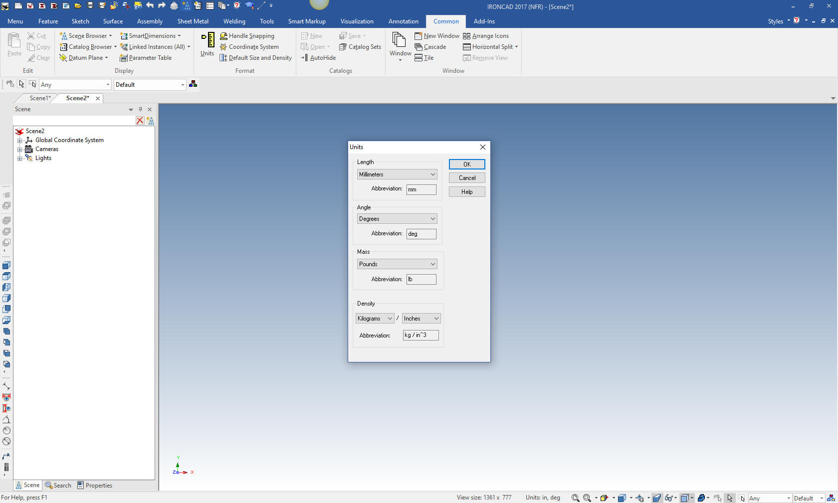
Here is IronCAD. My default is inches, so we set the units to
mm. Let's get started.
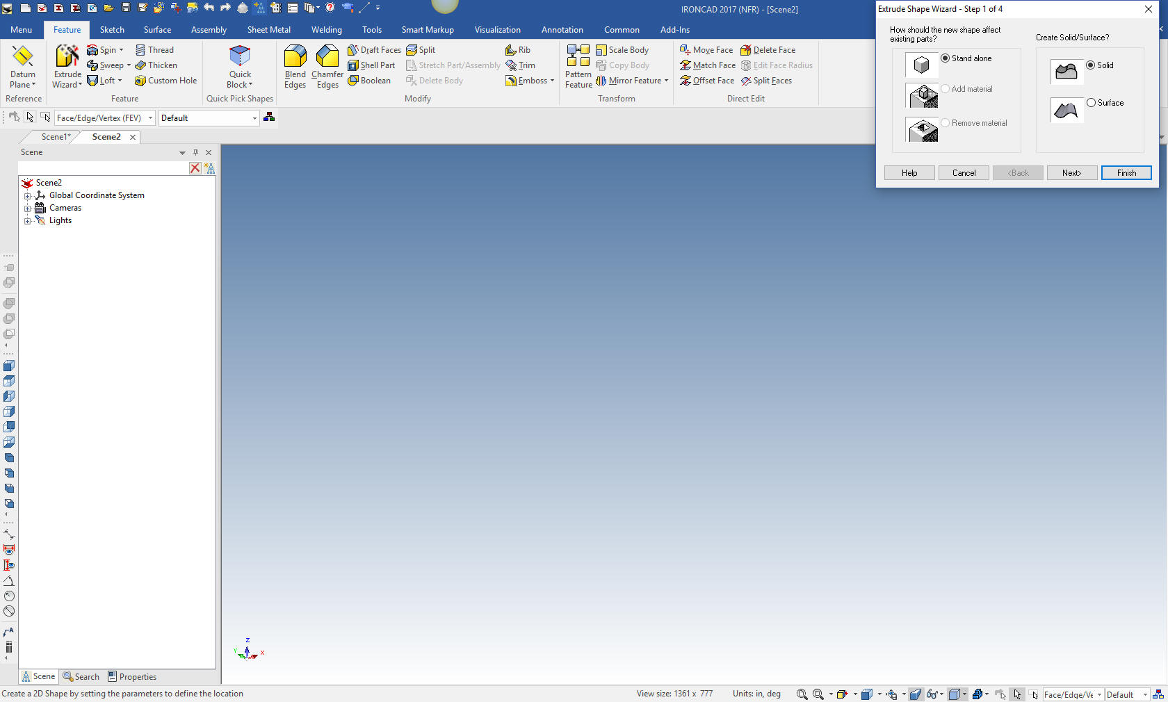
We
insert a sketch with the extrude wizard. We will create a stand
alone part.
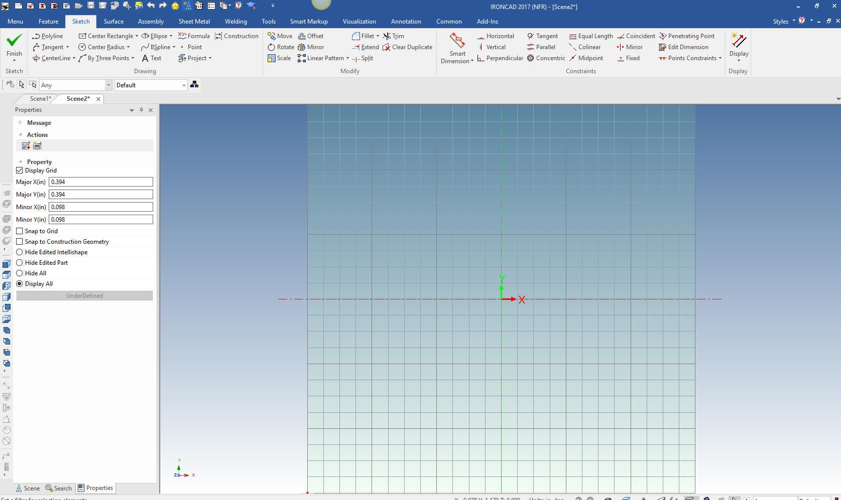
We select finish
and the sketching plane comes in ready to go to work. This is an
automatic extrusion and we will set the thickness later
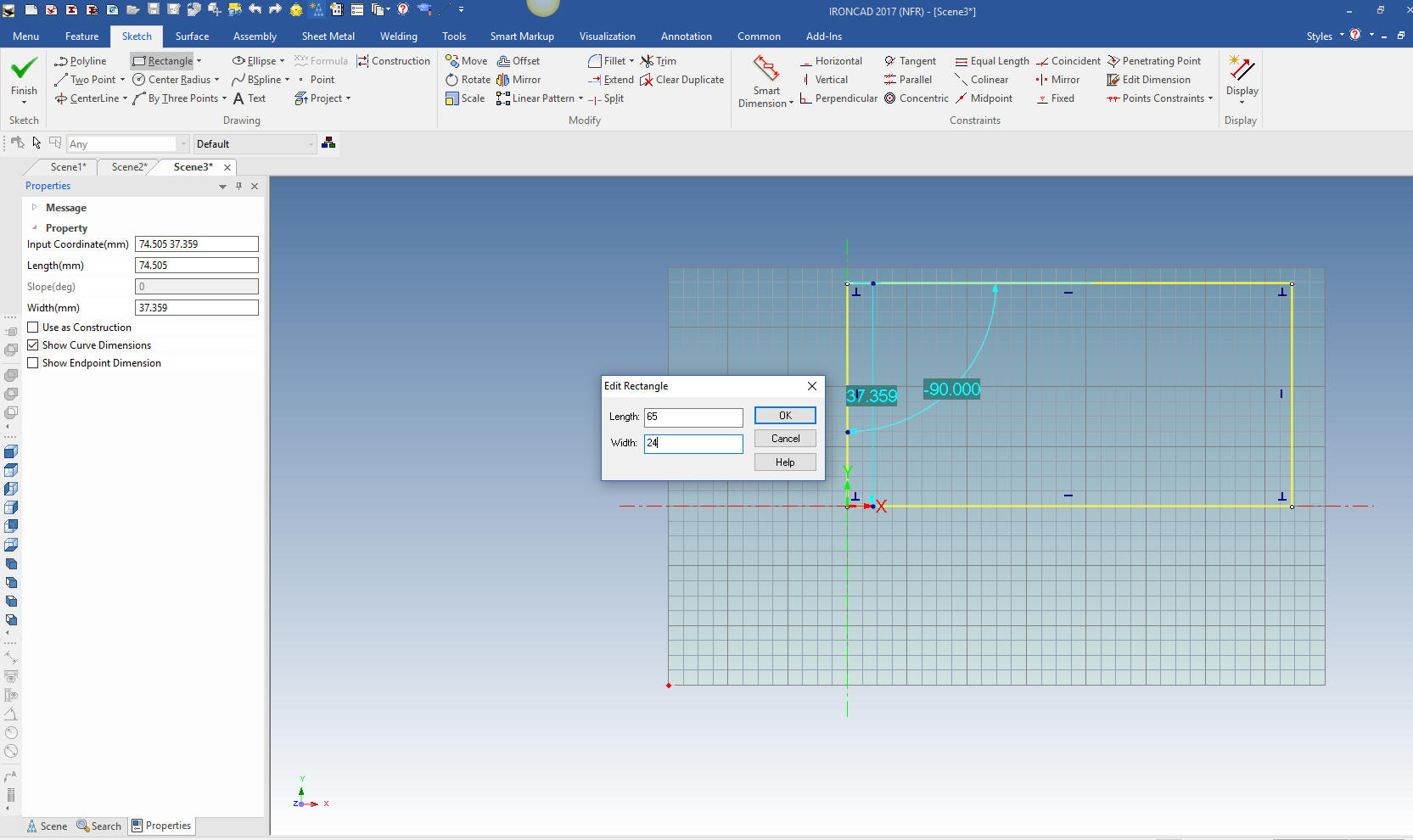
I first create a rectangle with the
rectangle with corners command. I use the right mouse button that
allows me to input the size of the rectangle 65 x 24.
Note: I have to make
a confession. I never knew about the right button edit function
until I started doing these exercises. It shows you how little I
used the sketching function. I have been using this program for
almost 20 years with tens of thousands of design hours.
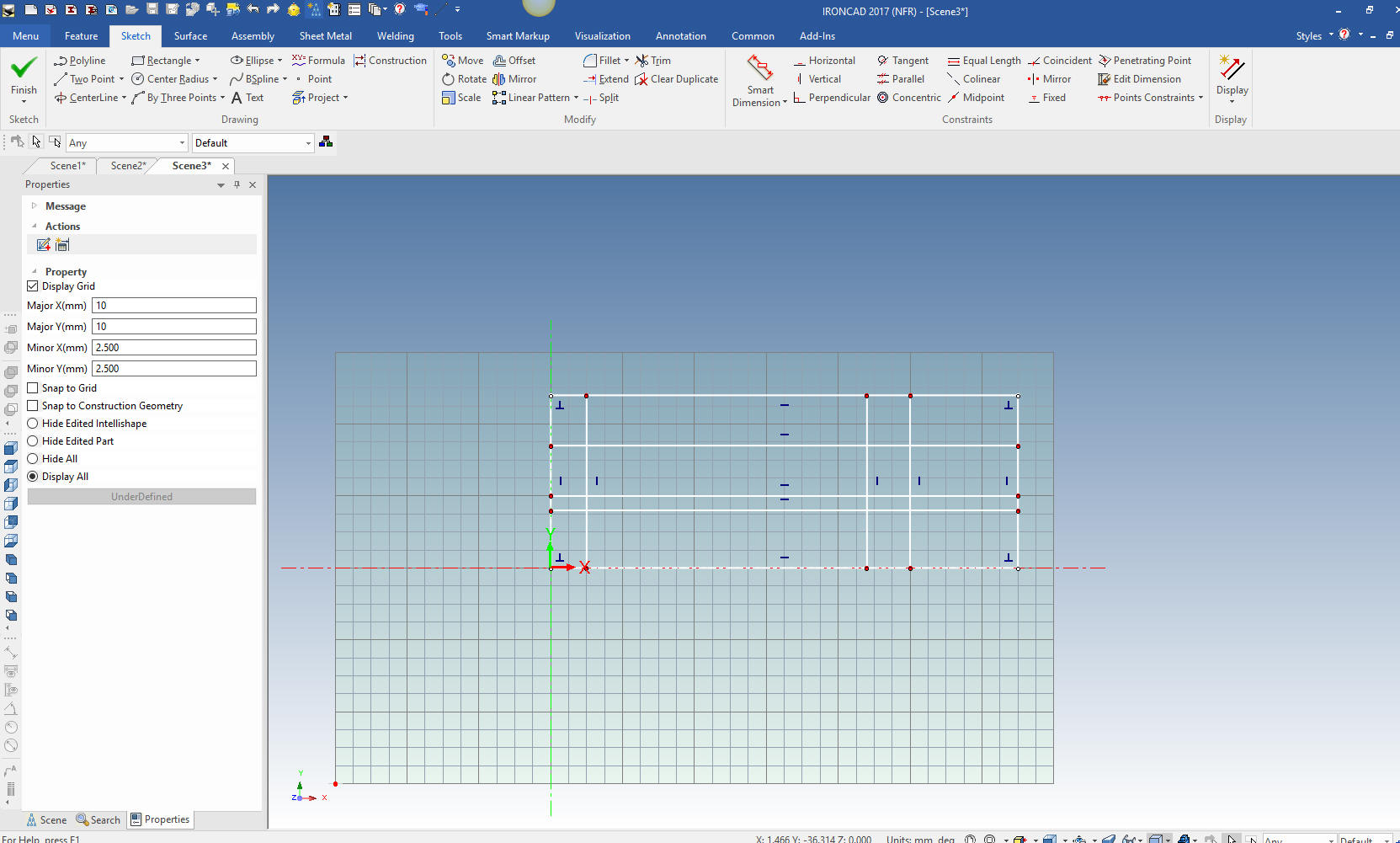
We will now create the vertical and horizontal offsets that are
the basics for our part. We will focus on the bottom profile here.
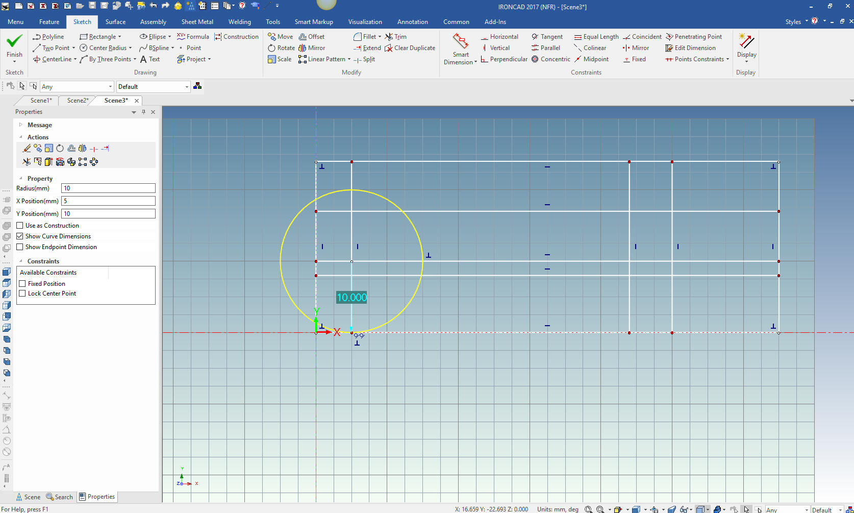
We
will add the 10 mm circle by center and location. No need to input a
dimension the graphics drive the dimensions.
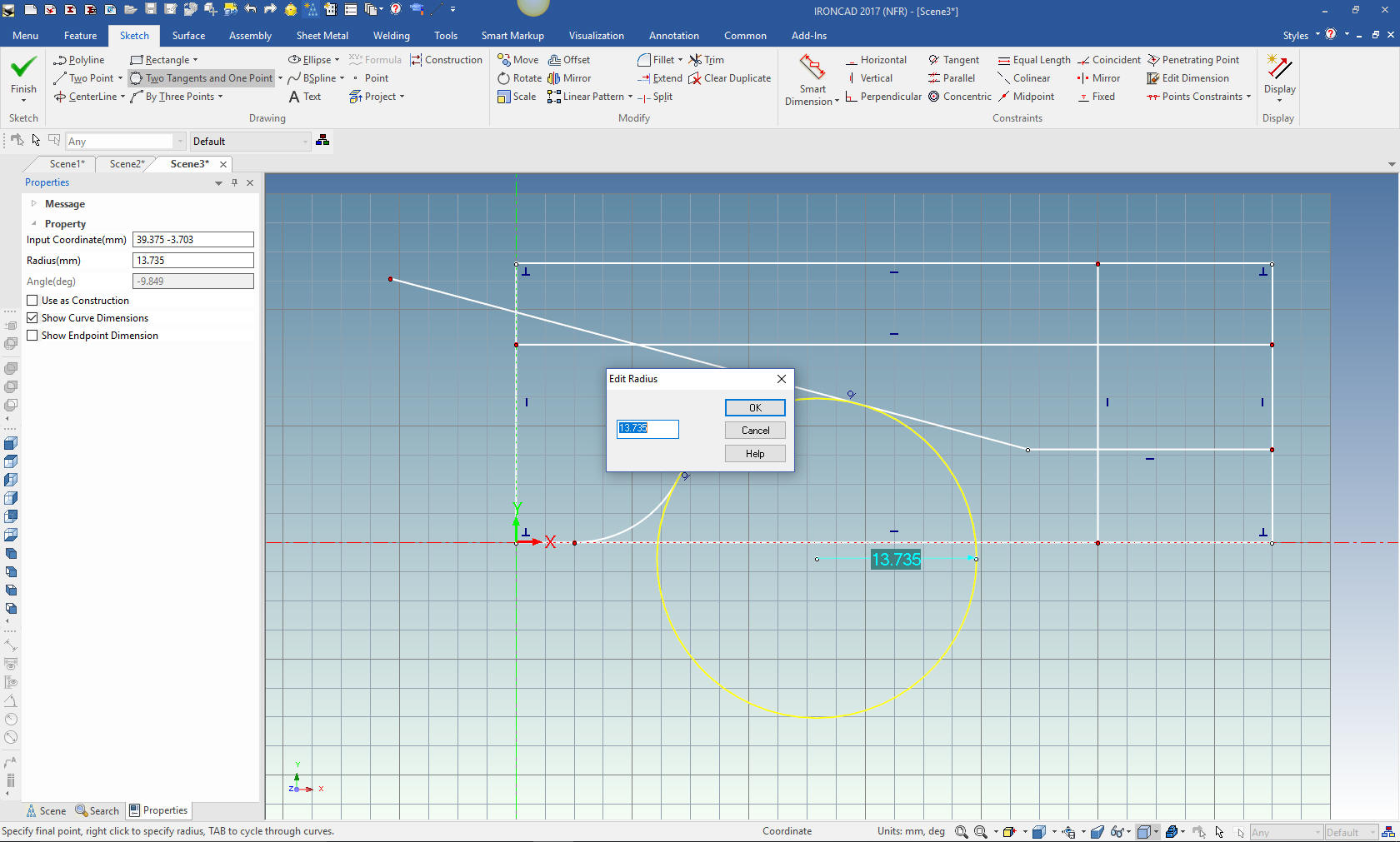
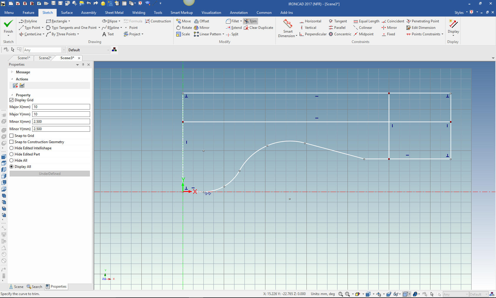
We
will do some trimming or deleting construction geometry to make it
more clear for the creation of the angled line. We create a two
point line with the right mouse button and set the angle leaving the
length arbitrary.
We
clean up a bit more and put in a two tangent and point circle using
the right mouse button which brings up a dialog box we enter 14.
We
trim the entities and are ready for the top profile.
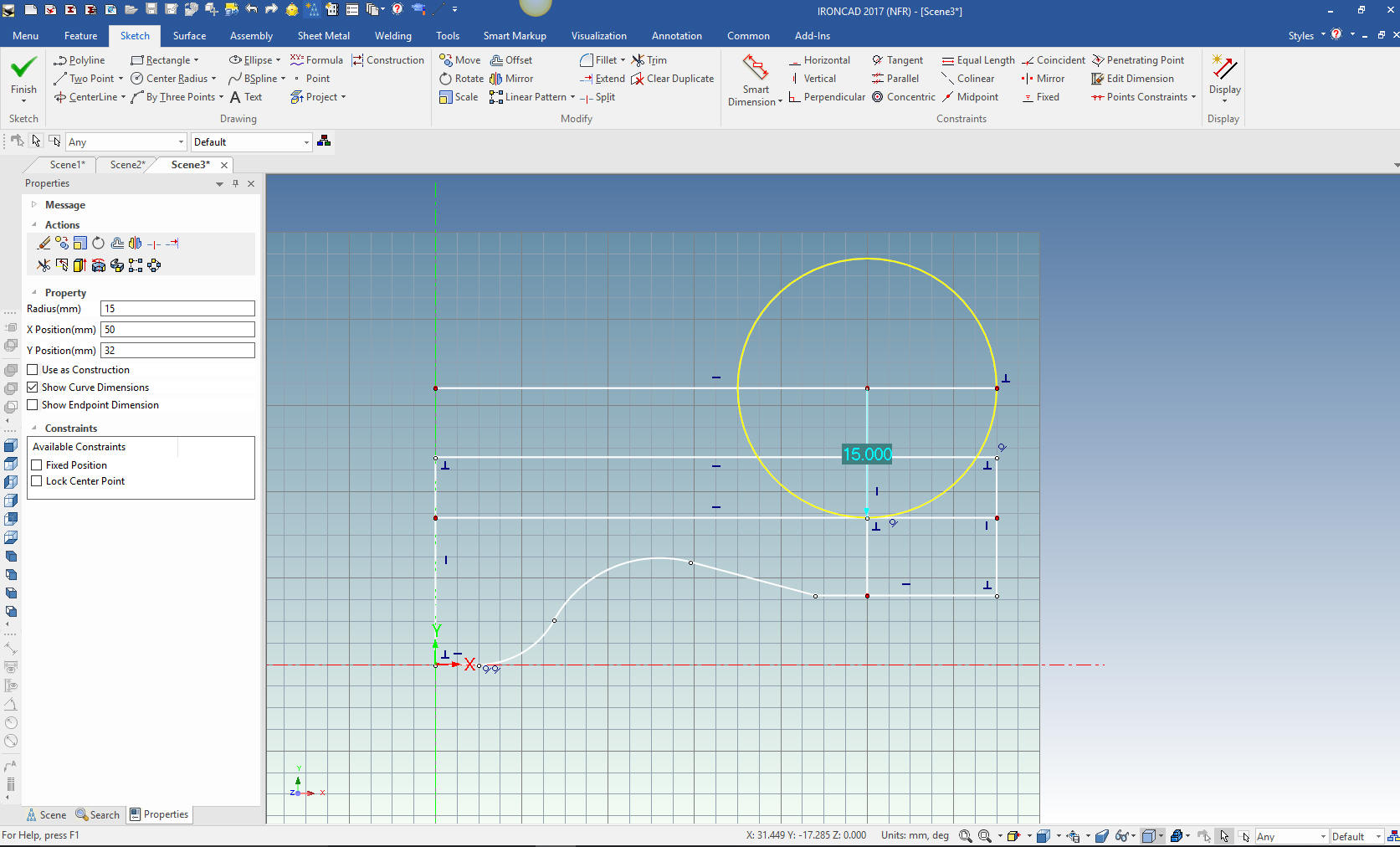
We
have to create another offset line from the affected horizontal line
at 15 and extend the applicable line to establish the center point
for the Radius. Again we let the graphics drive the dimension. I
will not concern myself with the R 10 since it is basically double
dimensioning.
We
just trim the entities and we are done with our sketch.
What
are you talking about, Joe, there are blends and chamfers??
Why waste your time sketching when putting in a blend or chamfer is
much easier. This is what I have called "Feature Based Modeling" as
compared to "Sketch Based Modeling" (if you can even consider
sketching, modeling).
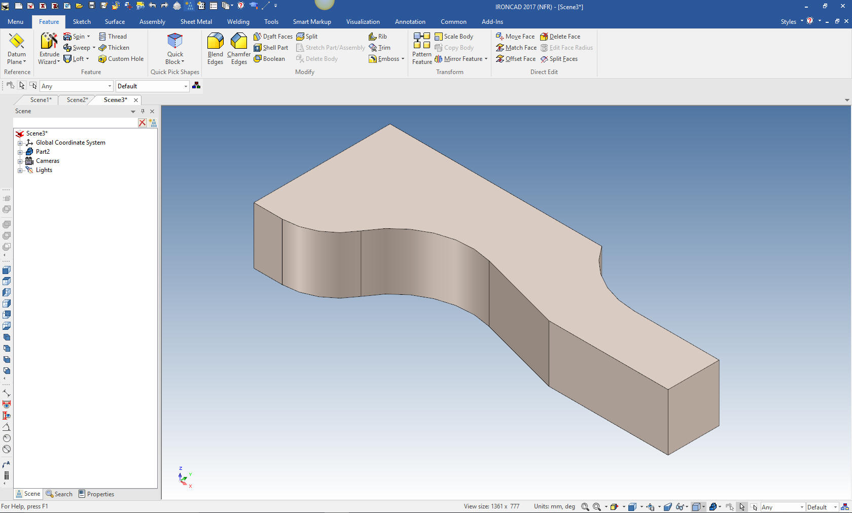
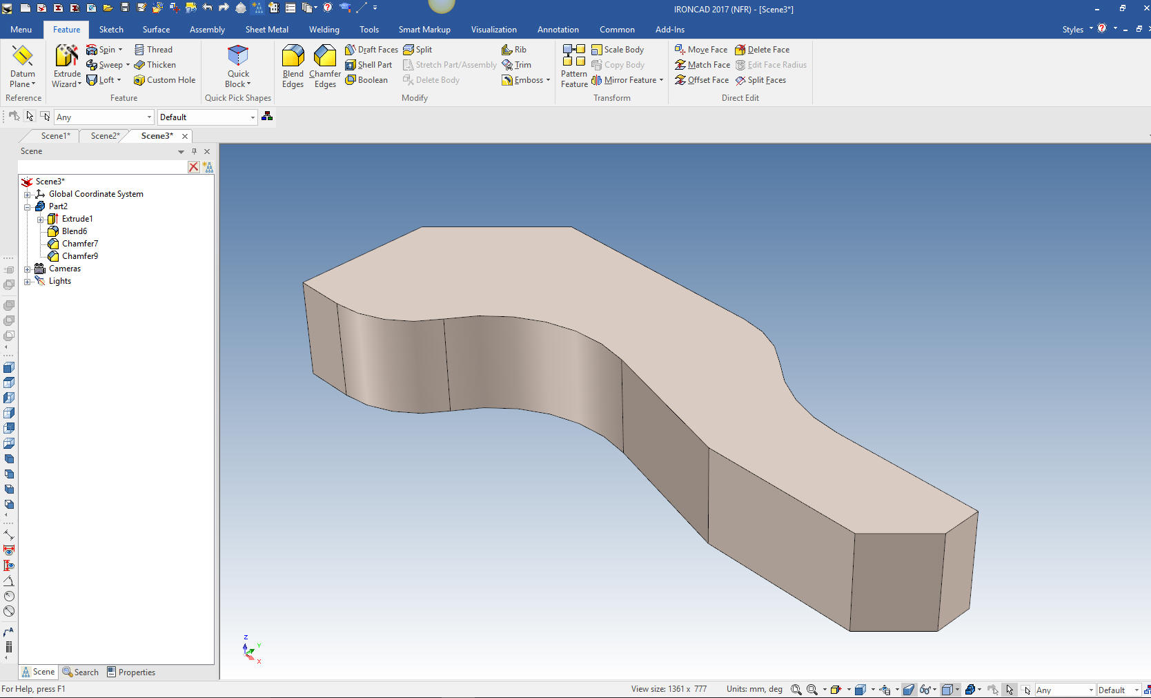
We select finish and the sketching of our part is done. We set the
thickness to 10mm
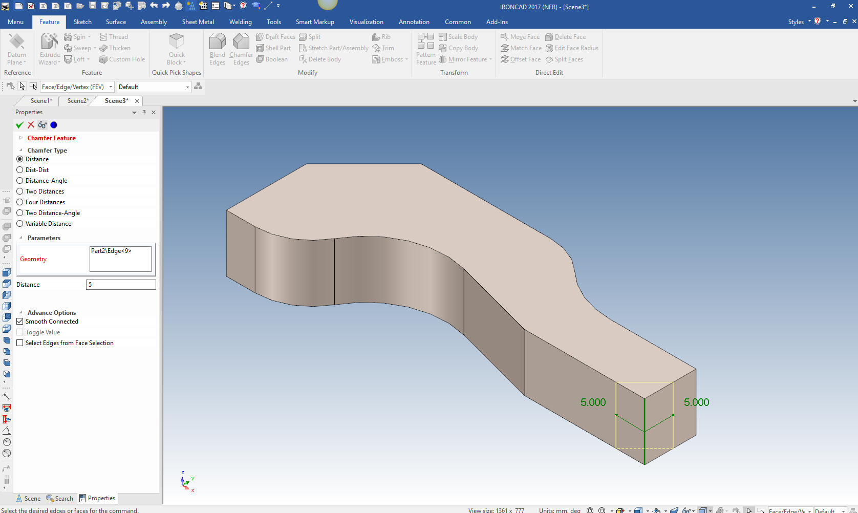
We just add the blend and two chamfers.
We
are done with our part.
Here is the drawing.
When you convert drawings to 3D you should also create a fully
detailed AID (drawing). To assure you have duplicated the part.
It is
very important that you look into how you or your engineers are
creating the parts. Streamline Sketching and Feature Based Modeling
is easy to learn and implement. It, alone, will increase
productivity 10X. Now, IronCAD with its unique integrated
history/direct edit functionality can increase your productivity
another 5X or more with changes! Again, time is money in
engineering.
More on Streamlined Sketching and Feature
Based Modeling.
To experience this increased level of productivity, please download
IronCAD for a 30 day evaluation. Legacy data is no problem, IronCAD
can read the native files of all of the popular programs. IronCAD is
a great replacement for the subscription only Autodesk and PTC
products.
Give me a call if you have any
questions. I can set up a skype or gotomeeting to show this part
or answer any of your questions on the operation of IronCAD. It
truly is the very best conceptual 3D CAD system.
If you are interested in adding professional
hybrid modeling capabilities or looking for a new solution to
increase your productivity, take some time to download a fully
functional 30 day evaluation and play with these packages. Feel free
to give me a call if you have any questions or would like an on-line
presentation.