IRONCAD vs Fusion 360 Lesson 17 3D Modeling Techniques Defined
Alternate Sheet Metal Modeling Streamlined Sketching/Feature Based Modeling
The modeling technique is
hugely responsible for the level of productivity. Those of you that
are only trained in the sketch, sketch, constrain, constrain world
are truly limited by not using the freedom of Streamlined Sketching
and Feature Based Design,
that is available in even the most Pro/e-ish of CAD systems. If your
designers are designing in these very unproductive and time
consuming processes it might be time to review your standard design
processes. Don't have any do you? When I introduce IronCAD's very
flexible design paradigm I have a hard time to get the Pro/e clone
users, like Solidworks and other programs to understand the drag and
drop design paradigm.
Download
IronCAD/Inovate and take
the one day and 17 lesson course. I get rave reviews from my new
customers. Give it a try, this is a fully functional 30 day
evaluation with all of the native translators so you have access to
your legacy engineering information.
IronCAD Self-Pace Training Course
I saw the
following video challenge on linkedin and thought I would give it a
try. I actually did it before I watched the video, so I
did it a bit differently. This will give you an idea how different
and flexible IronCAD is compared to the conventional Pro/e clone and
to the not so conventional Fusion 360. Fusion 360
Monthly Challenge: September 2019
Alternative Sheet Metal Design
I was introduced to
3D CAD in 1982 with Computervision CADDS 4, Found PC base 3D CADKEY
at Boeing in 1986, Started using and selling it in 1987. This was 3D
wireframe, no fancy sheet metal modules. We even had unfolding
programs for the wire frame design.
Here is an image of a
this part in wireframe. With CADDS 4 we started with one color!
Green on Black! They added Color for $35,000 per seat with CADDS 4X.
I sold PC Based 3D CADKEY in 1987 with full color with 90% of the
functionality of CADDS 4 and Catia 2 for $9000.00 with CADKEY, a 386
computer and 19in CRT. CADDS 4 and Catia were well over $100,000.00
per seat.
Are you looking up or down? This used to drive the engineers
crazy. Yes, in those days 3D CAD was only in the realm of draftsmen!
Enter solid modeling in
1995. We started modeling our sheet metal like we do all of our
models. I am afraid the many of the new millennial engineers really don't
know you can probably do your sheet metal design faster and easier than
with the sheet metal modules. Now, I suppose if I only designed
sheet metal parts it might be advantageous. But most of us design
projects where a variety of mechanical design is used. Machining,
sheet metal and other fabrication. So you may design just a few
sheet metal parts.
Being a Boeing trained draftsman, I have
extensive sheet metal design experience. We would do flat
pattern development on undimensioned drawings to .005 tolerance.
They would photograph them on to the tool.
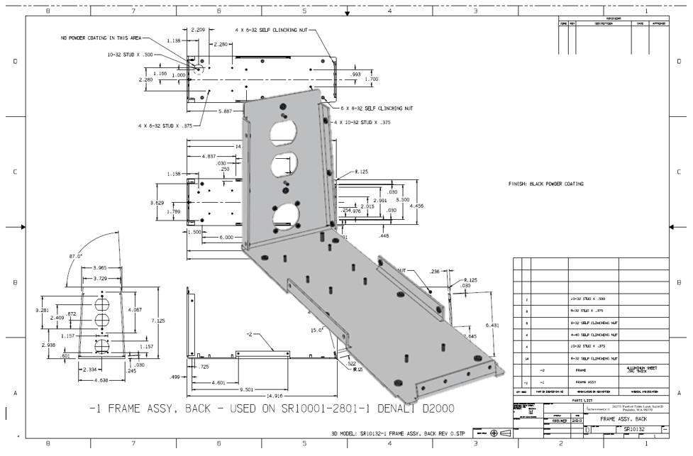
Today, I
just use the basic solid modeling tools. In IronCAD I may grab a feature from the sheet metal
module, but that is it.
Here is just one of my many jobs.
IronCAD vs Fusion 360
While creating 3D models from drawing is the very best
way to learn 3D CAD and maybe some design techniques is does not
expose the designer to the design flexibility necessary in product
design. IronCAD is all top down due to the single model environment.
Creating mating parts is a cruise. But modeling is just one aspect of a
well designed productive 3D CAD system.
I would do a
video, but I really am not good at it. So I will show you step by
step. I will try and get IronCAD support to create one. They are
very good.
I always create the part before I watch
the Fusion 360 Video, so as to not taint my process. Of course,
there are a multitude of ways to create a model. There is no right
way, just more productive ways. From what I have seen from these
very complicated processes done by the Fusion 360 fellow, it is not
just limited by the 3D CAD system.
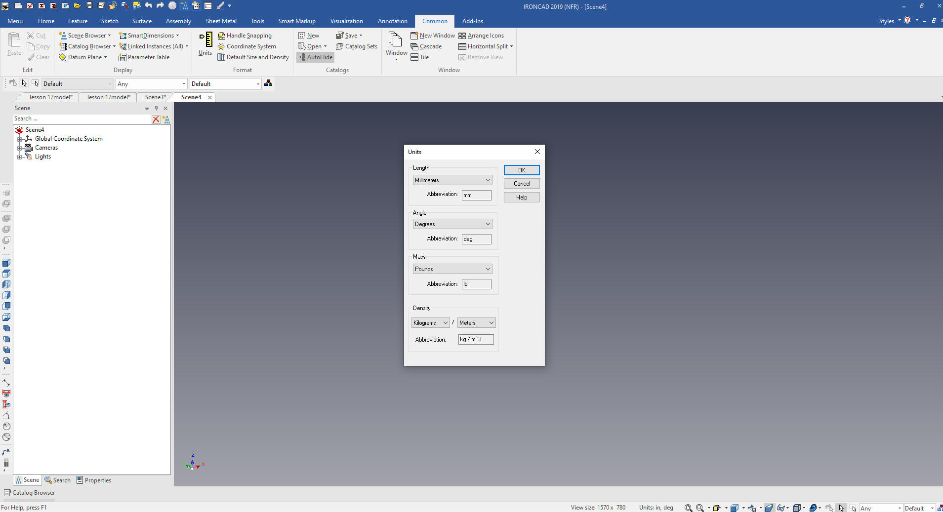
Here is IronCAD. My default is inches,
so we will set the units to mm. Let's get started.
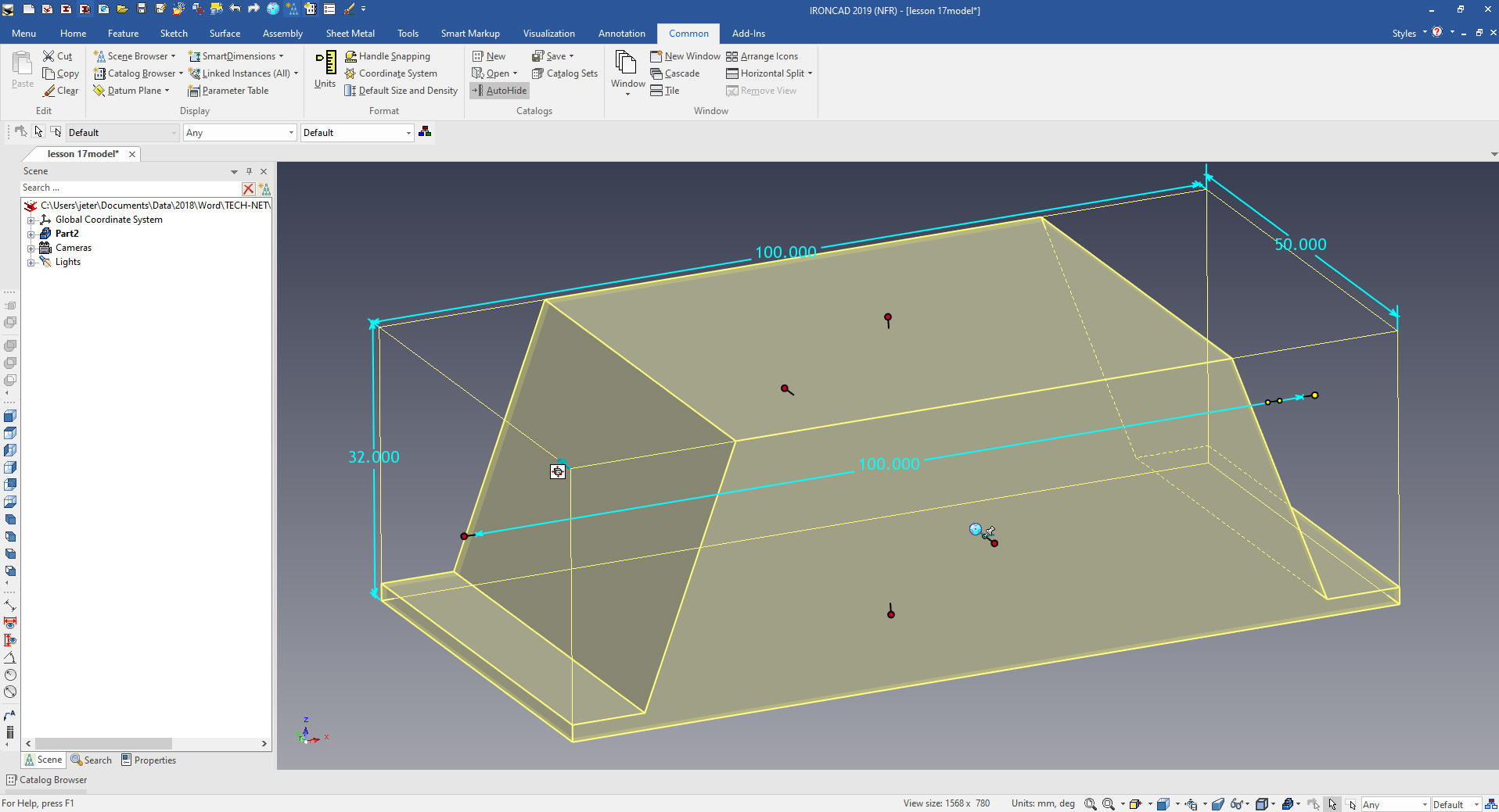
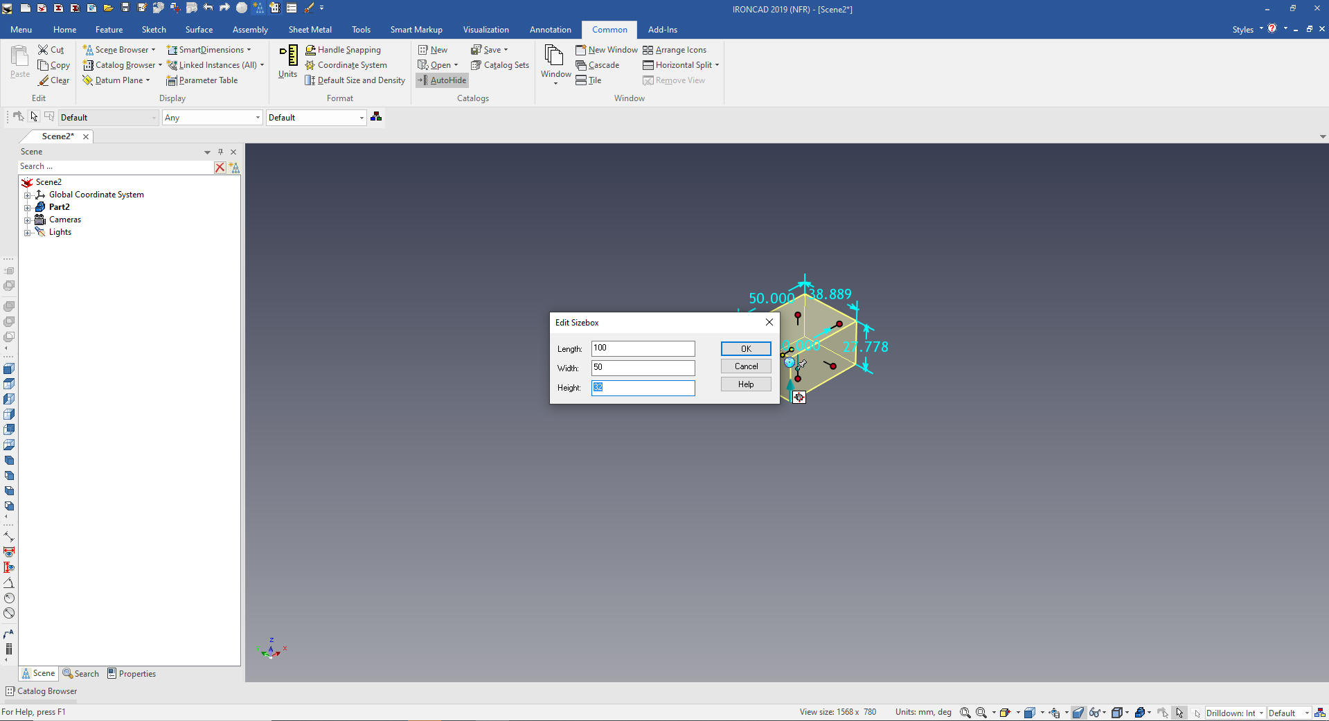
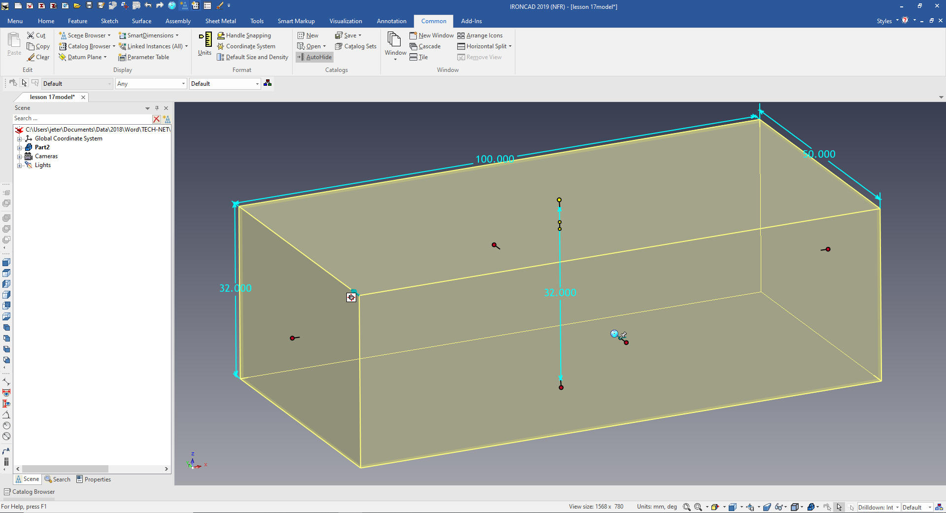
I drag and drop a block into the
scene. I size it 100x50x32
Note: Why does IronCAD call it a scene instead of a workspace?
IronCAD was first released as a graphic design program called
Trispectives. It still has much of the graphic design functionality.
It truly is a wonderful mixture of professional 3D CAD and graphic
design, which puts it in a much more flexible category as compared
to the Pro/e (Creo) clones.
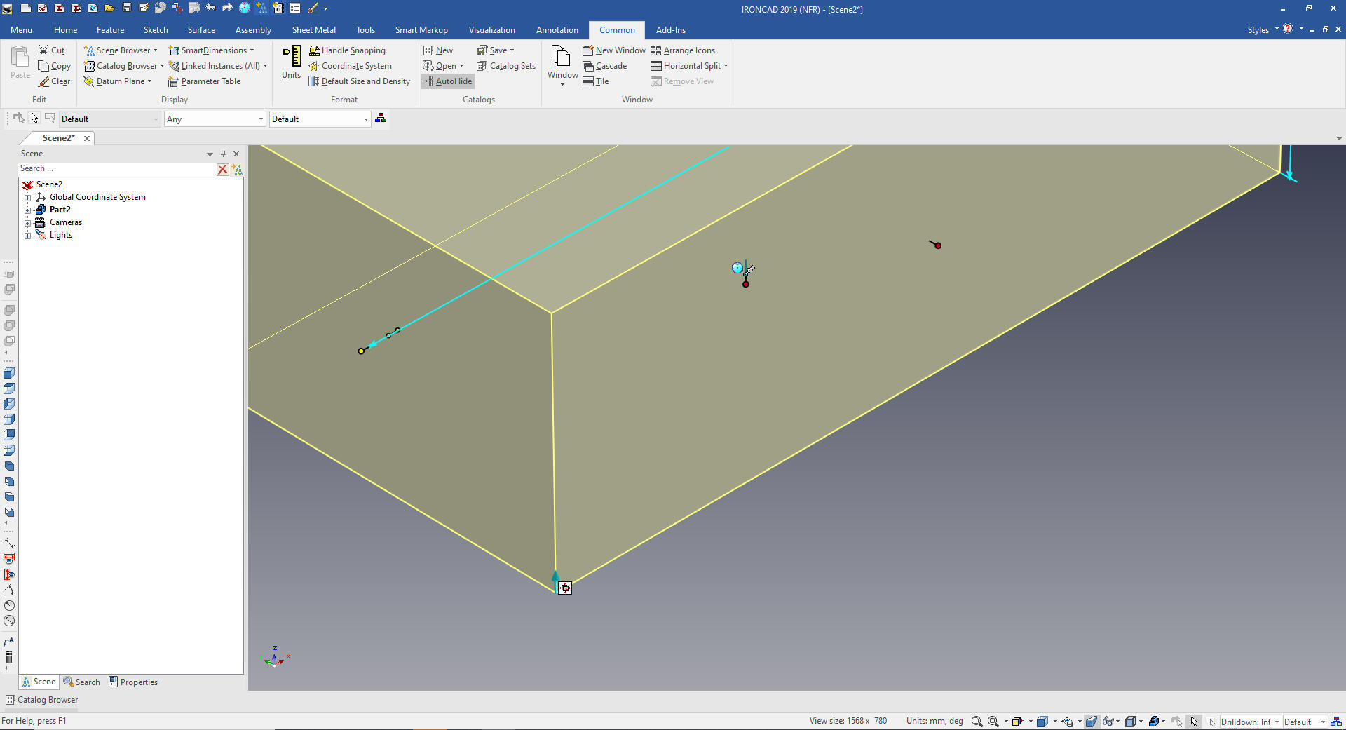
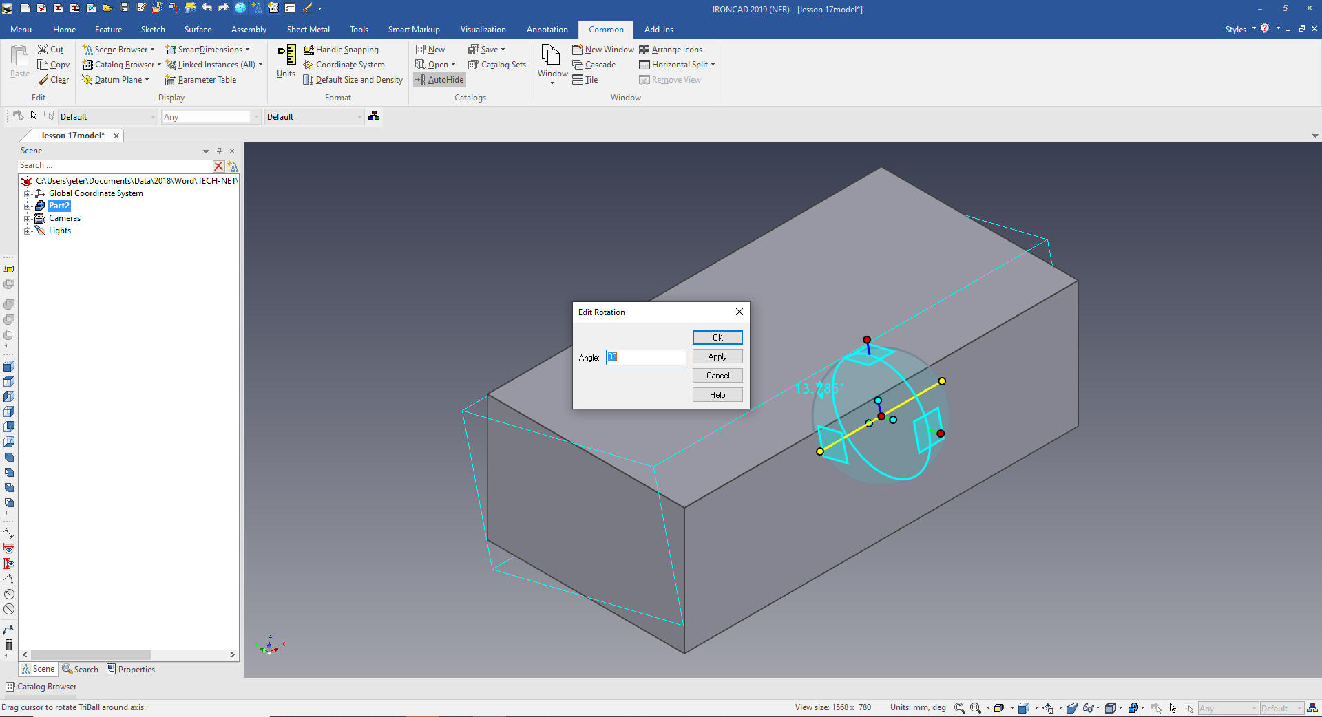
Look
at the small arrow in the corner. All of the Intellishapes are based
on sketches. The arrow indicates the extrusion direction. I am going
to rotate the block into a different orientation I want to work.
We
rotate the block 90 degrees with the Triball. We want to rotate the
part, which is shown with a blue outline.
IronCAD has 4
different levels of operation.
Yellow - Assembly Blue -
Part Yellow - Feature (as shown above) Green - Face or
Surfacee
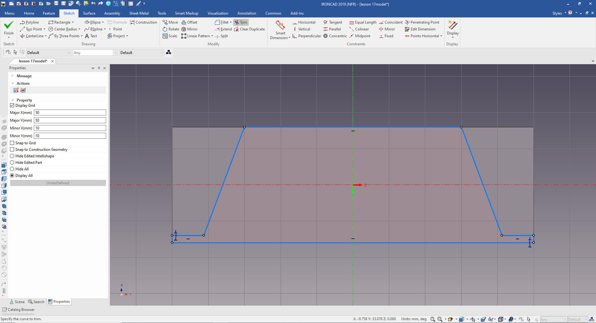
We
will resize it for the new orientation.
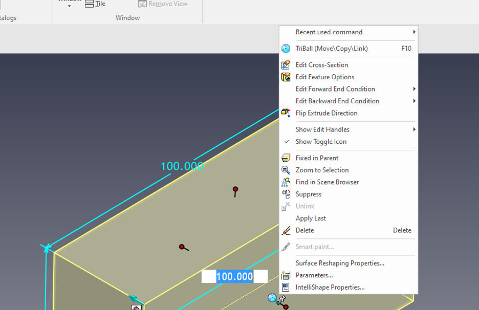
Now
we will "Edit Cross-Section" and modify the sketch. I have to tell
you this beyond clever!! IronCAD offers flexible functionality
beyond any 3D CAD system!
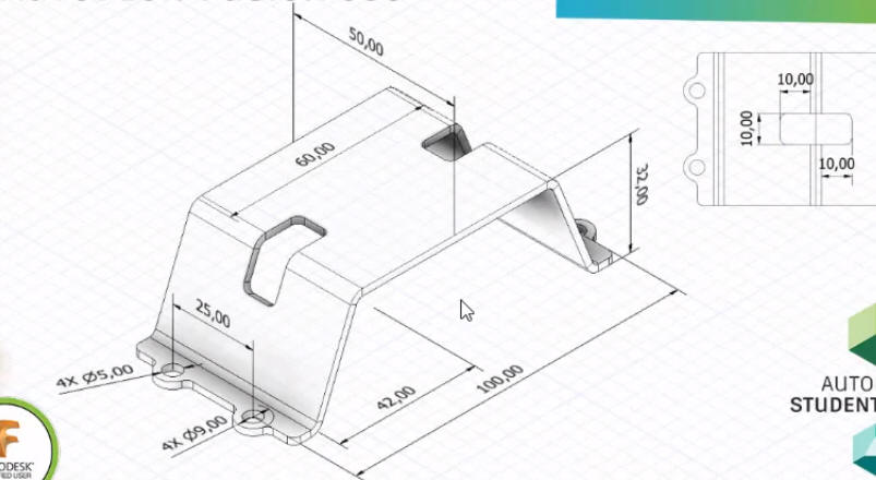
The
Fusion 360 fellow made a mistake. Notice the dimension in the Iso
drawing are from OML to OML. You have to dimension to the OML to be
able to inspect the part. This was a problem in the old day when
creating the part drawing. I will show you how to avoid these
problems.
Another problem with this drawing is it comes from
a center line that is not tied to a feature, hole or edge. This is a
no, no because it creates another level of tolerance. You will see
my AID (drawing) below showing the correct way to dimension this
part for inspection. Even though drawings in the past defined the
part, they also were used for inspection. We used to say "You can
make the part anyway you want as long as it matches the drawing."
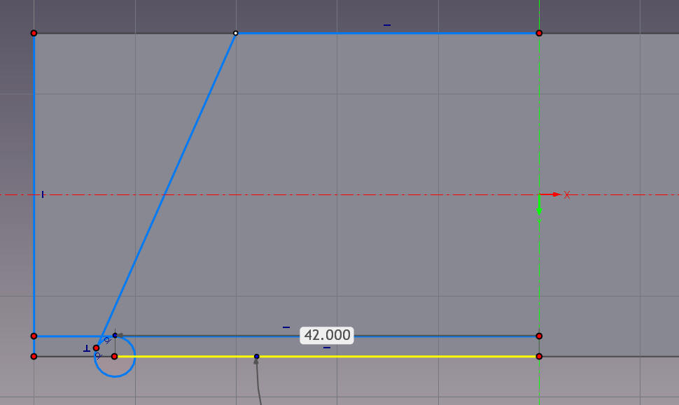
This is how you have t develop this part. Look at the 42
dimension it goes to the bottom OML and 30 dimension goes to the top OML.
These points do not connect. You have to create a circle the
thickness of the sheet metal and create a tangent.
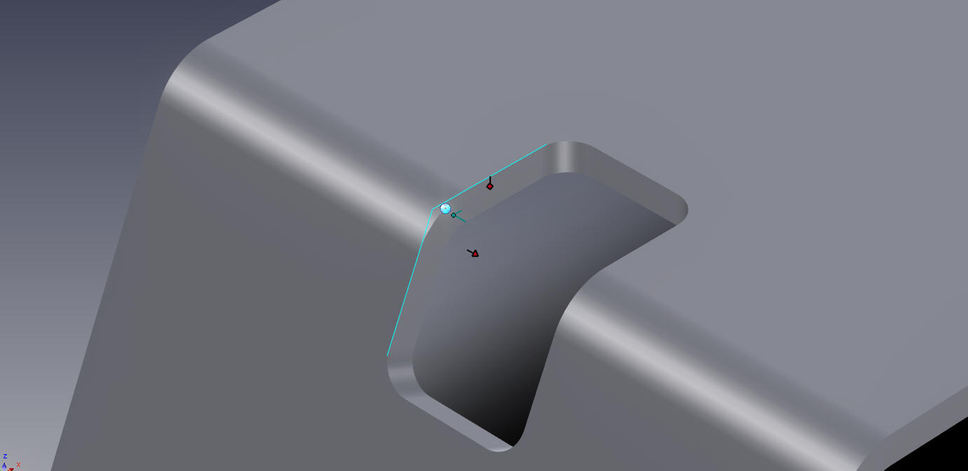
I
will use that line for my diagonal edge. I will finish up the
sketch. That is why the Iso drawing is not viable documentation.
We
exit and voila we have our base shape. I show it here at the feature
level.
Think this through for a second. We created a block,
oriented it and edited a sketch.
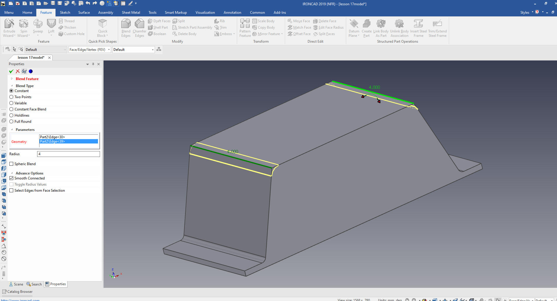
We
add the bend radii.
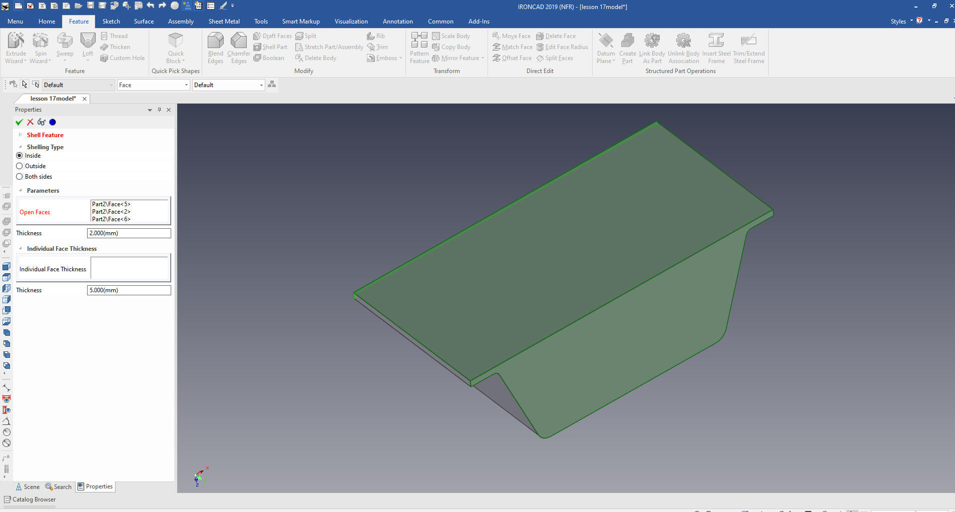
We
just shell the shape.
As I state above I was modeling sheet
metal part before they had the sheet metal modules. Now there are
very many unique sheet metal functions, and it may behoove you to
use them. But for most sheet metal parts this type of modeling is
much more productive.
We now
have basic sheet metal part.
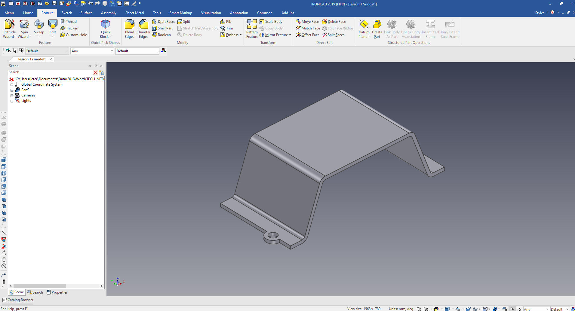
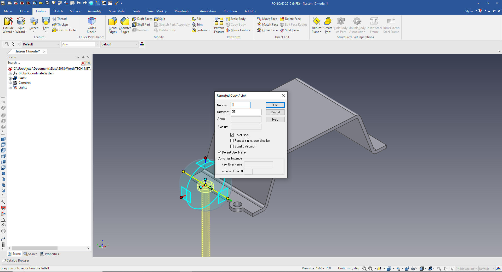
We now drag and drop a cylinder
on to the flange then we drag and drop a hole cylinder to the center
of the flange cylinder. We locate with the Triball.
We
select the two features, cylinder and hole cylinder in the scene
browser on the left, locate and link them using the Triball
The browser is a bit like a history tree, bud due to the single
model environment offers much more, profile (sketches), parts,
entities, assemblies, cameras, lighting, features in parts and more.
Again
we select all of the affected the features in the scence browser and
we mirror the features by moving the Triball (You free the Triball
with a push of the space bar) to the mid-point of the front edge.
You have many locating options with the Triball!
Now for the two cutouts. I am sorry but I am not going to go the
a flat pattern to design this part. Most companies do not supply the
flat pattern to the supplier. We want them to inspect to the
designed part. So I will create the cut outs in the model.
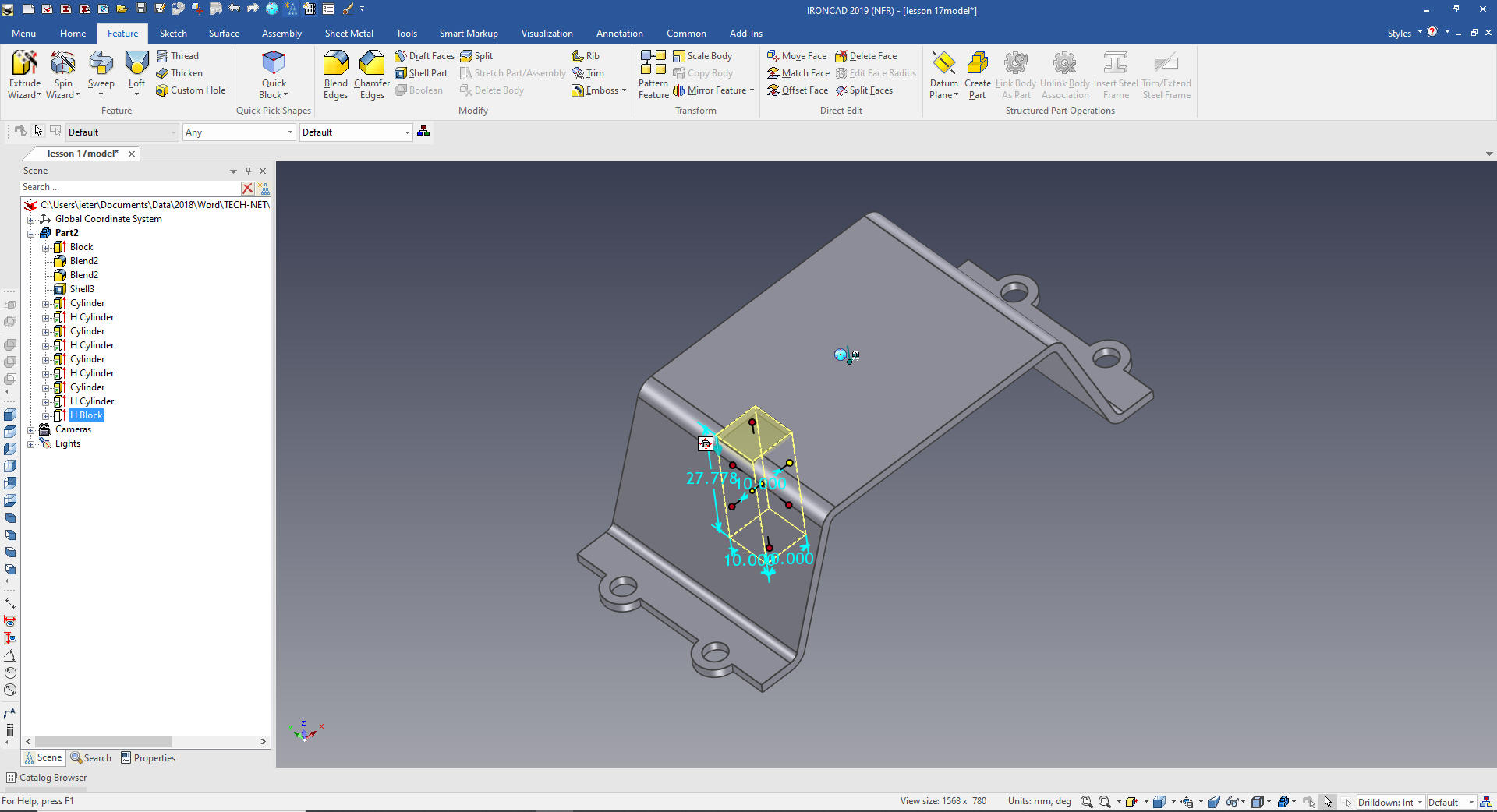
We
drag and drop the first hole block, locate and size it.
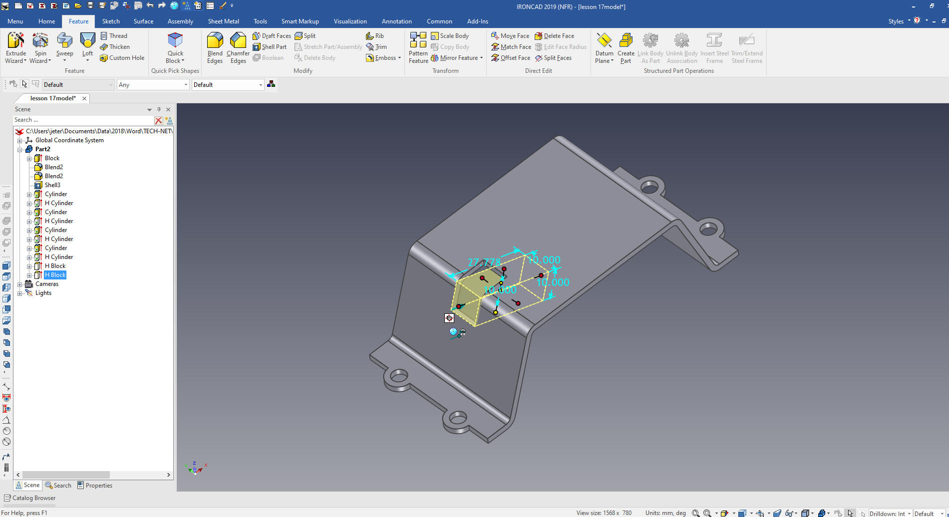
We
drag and drop another hole block on the diagonal face using the
exist cut to locate and size the cut out.
I
realized had to have a corner for my cuts. I Just created a sketch
and the intersection was available to snap to.
We
select the two feature, locate the Triball a the mid-point of the
edge as we did with the tabs and holes and mirror link the features.
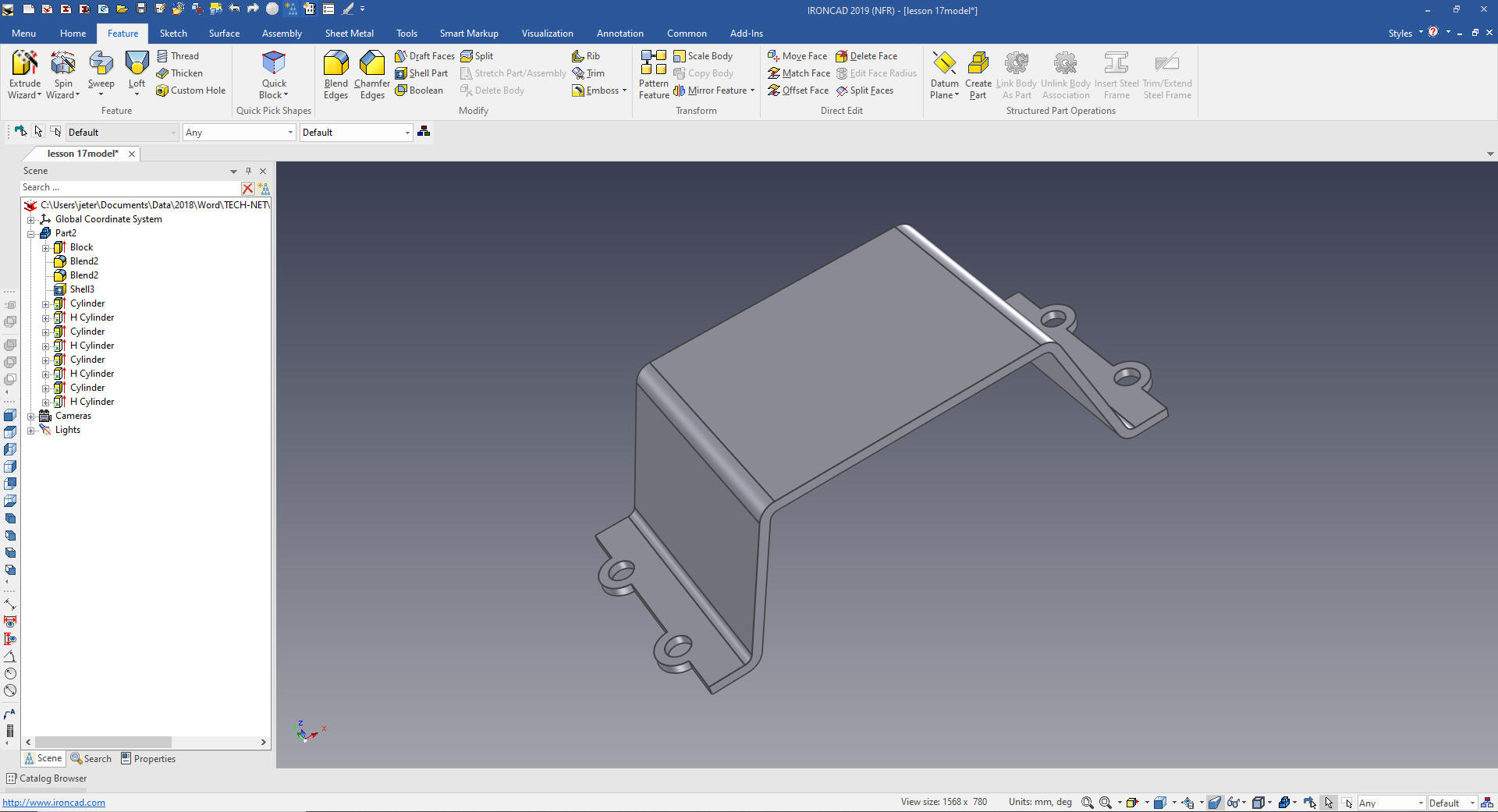
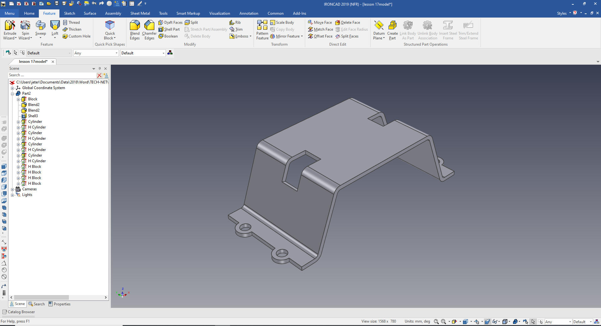
We
Select mirror link and we are done with the easy part of the model.
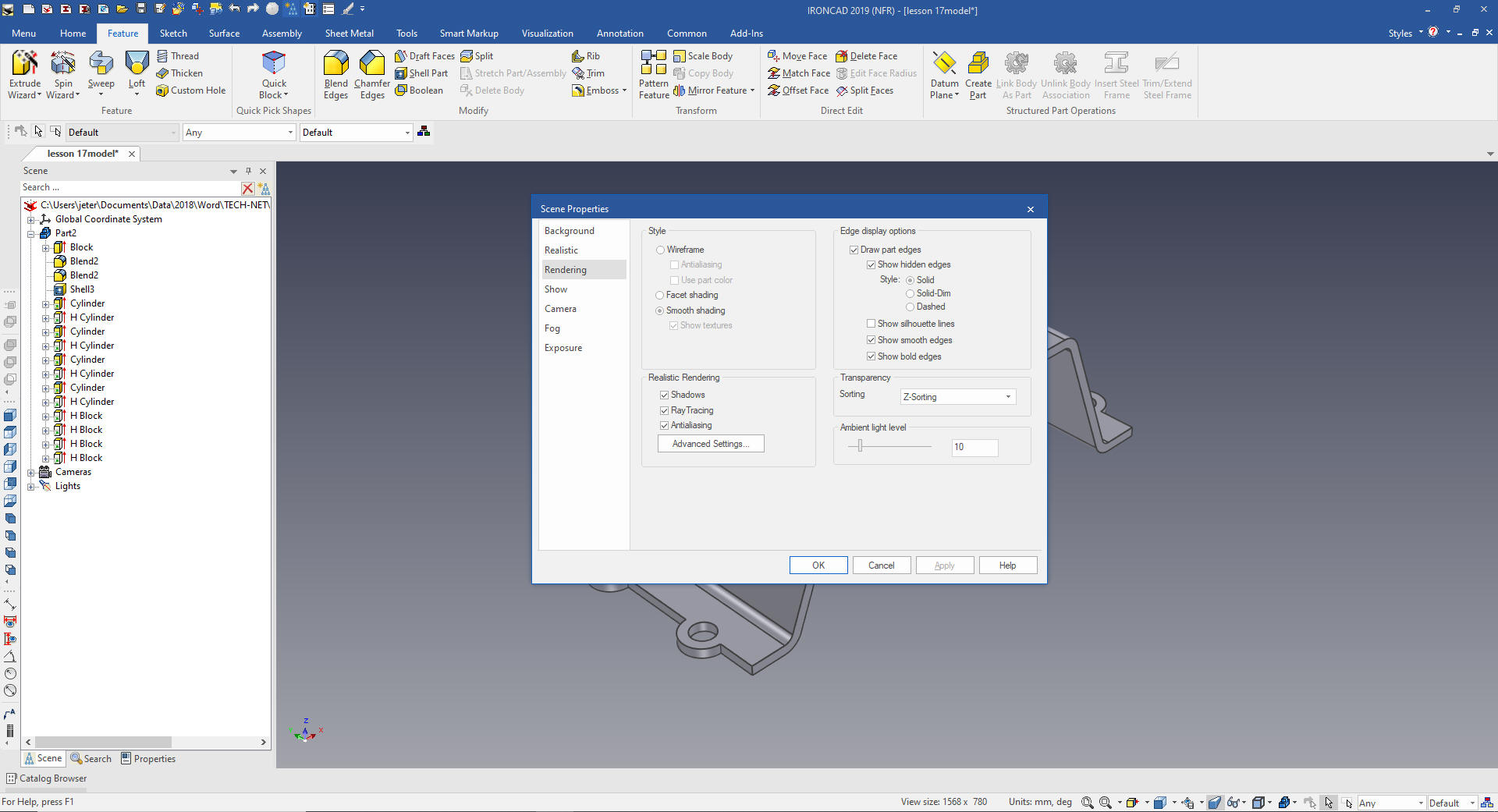
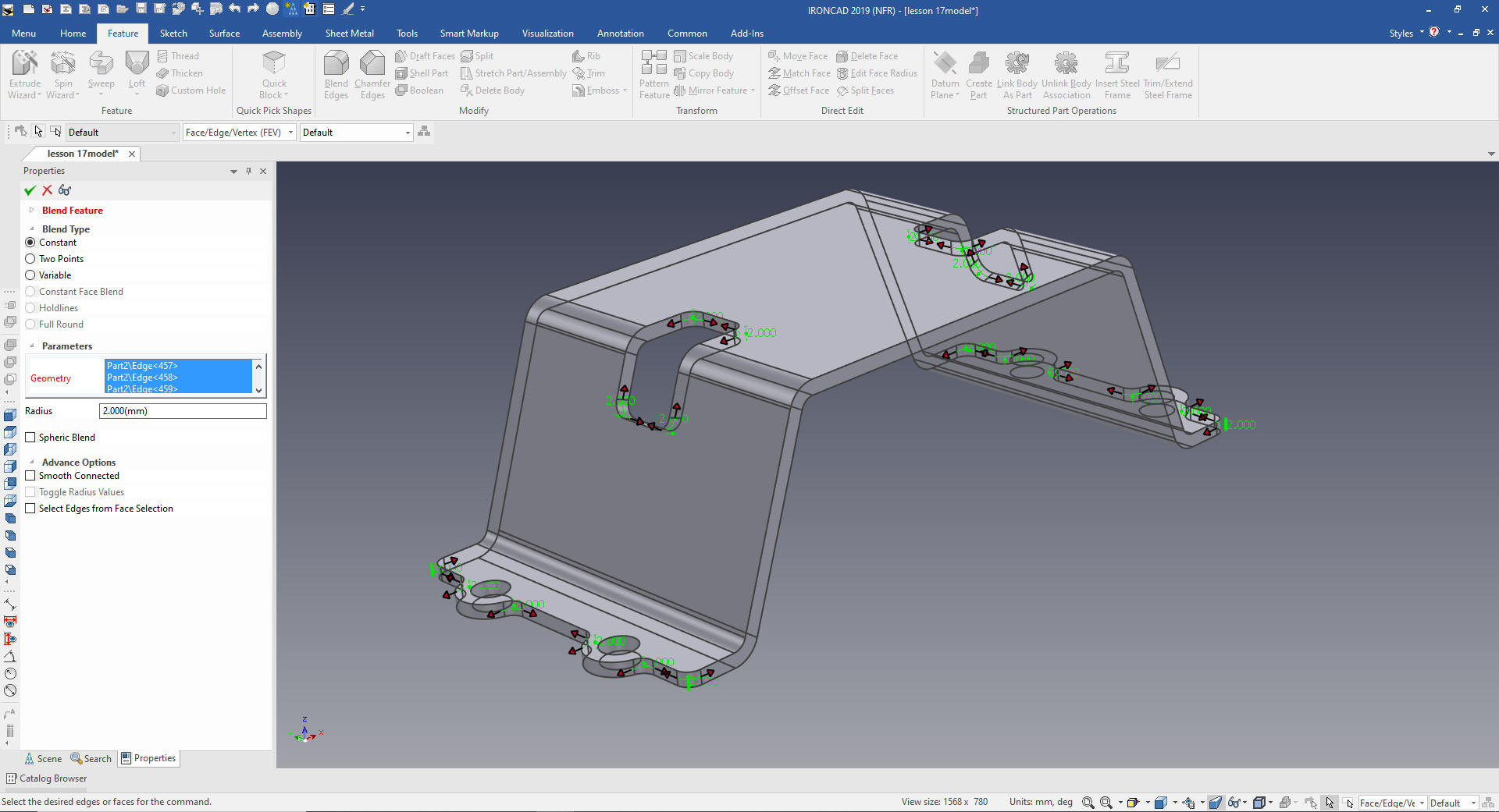
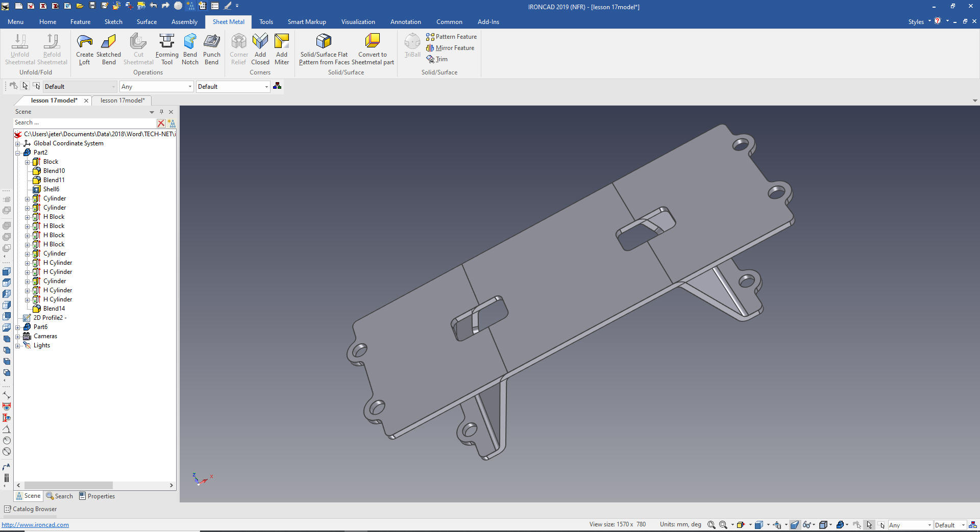
Now for the tough part - blends I right click in the scene and
select rendering in the dialog, we select "Show Hidden Lines" since
there are so many edged to select.
We put in the blends.
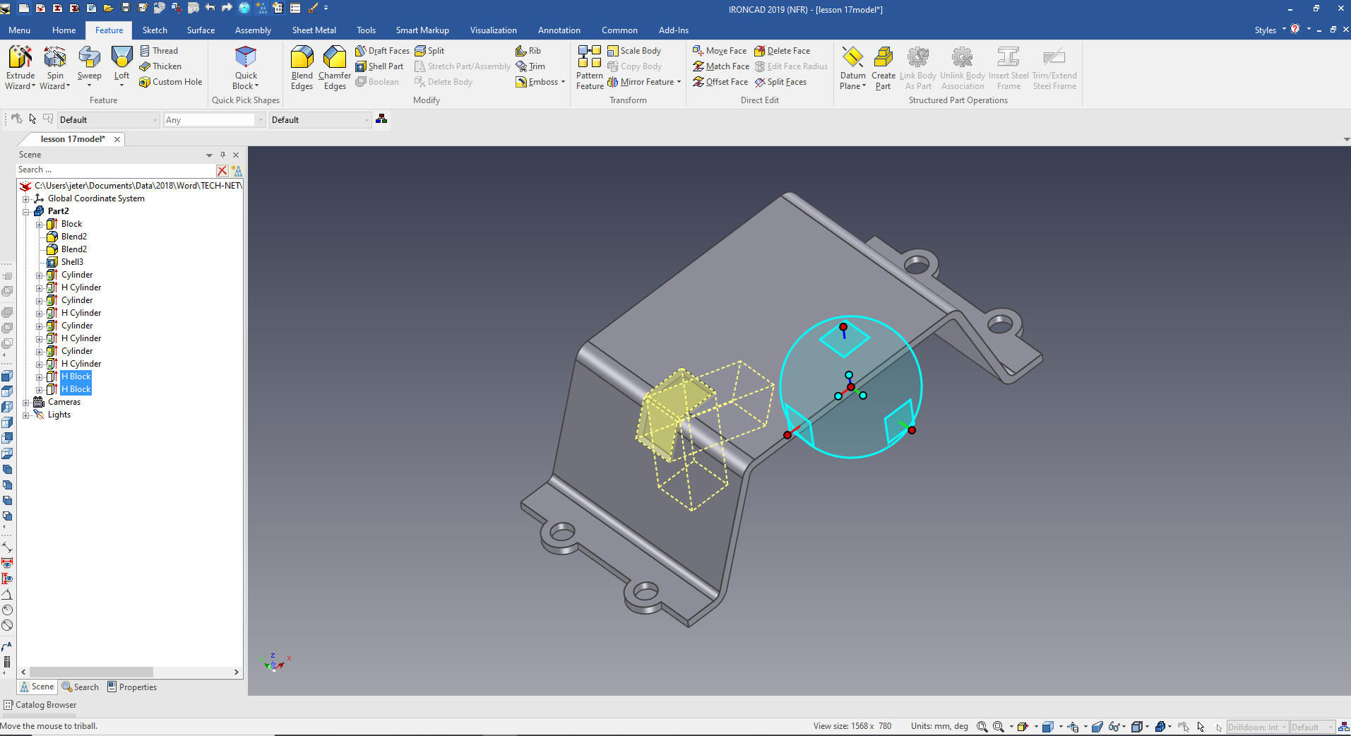
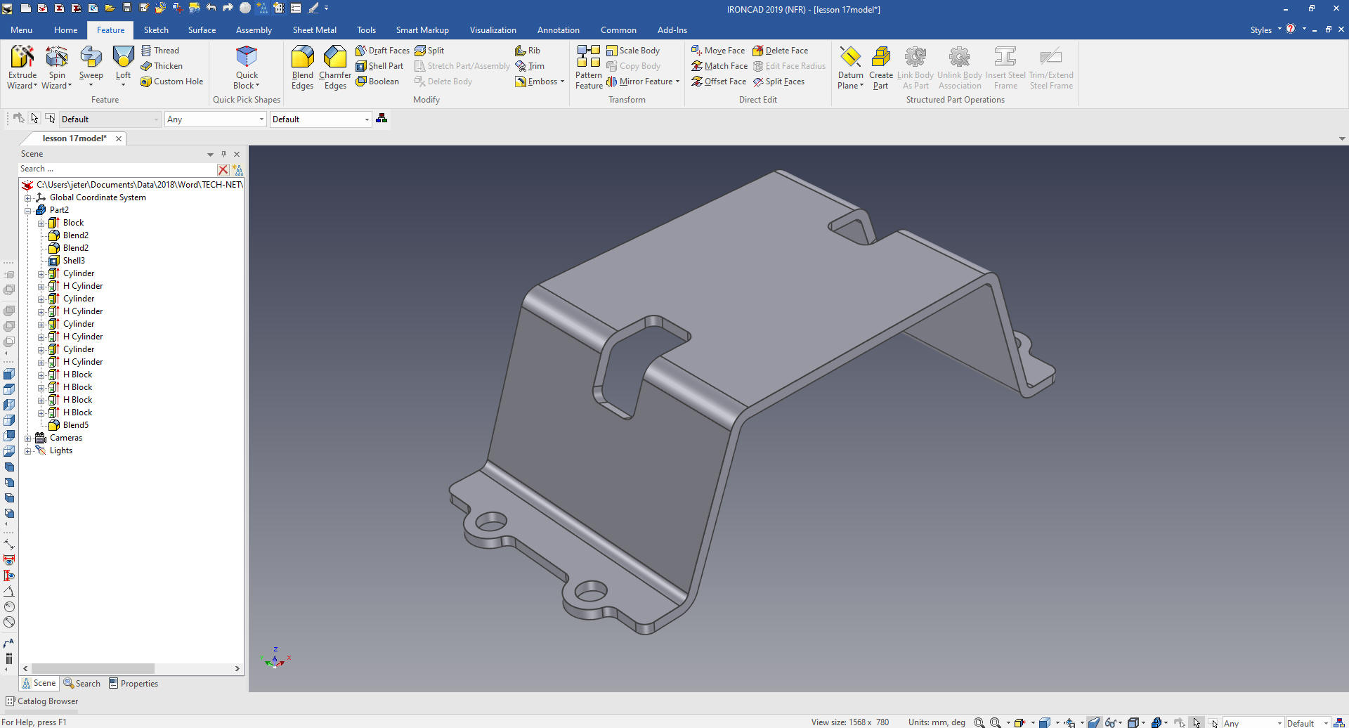
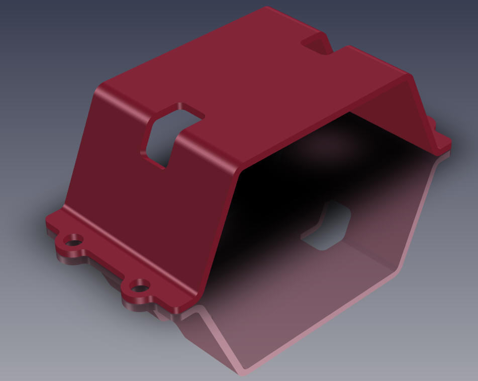
We
are done. If you watch the Fusion 360 presenter it is almost
tortuous all of the hoops he has to jump through. Honestly, can you
see this is a much better design paradigm?
While
ISO AIDs are a bit easier to understand, they leave much to be
desired to truly define the part. I expect all engineering
professionals to be able to understand a drawing, if you can't you
will be out the door.
Now we will detail the part correctly. Of course, we cannot really
detail a part by itself. We need to have the assembly so we can
define relationships of the features so both or more mating parts
align. So I will just defined the part so it can be understood by
manufacturing and those that may want to create the model.
When converting drawings to 3D you have to re-detail the part to
assure it is the same as the drawing.
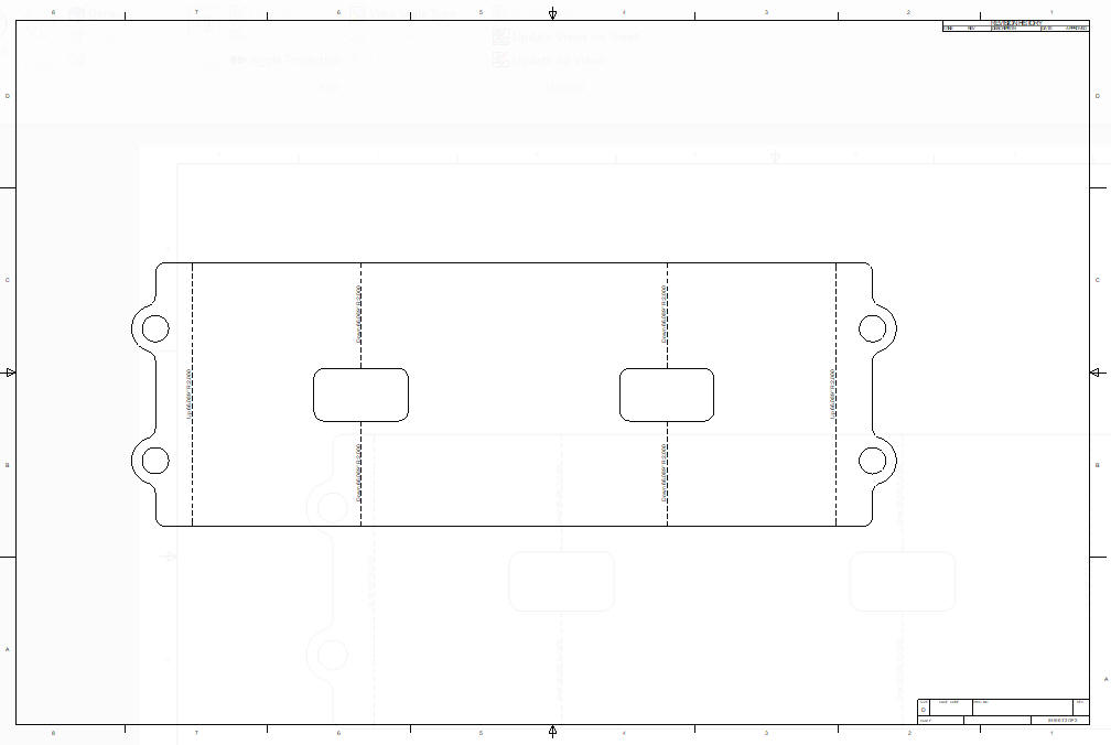
Here is the AID. IronCAD has a separate
documentation module.
Unless you are working in a sheet metal house you should send the
AID (drawing) and the 3D model to the sheet metal supplier to create the flat
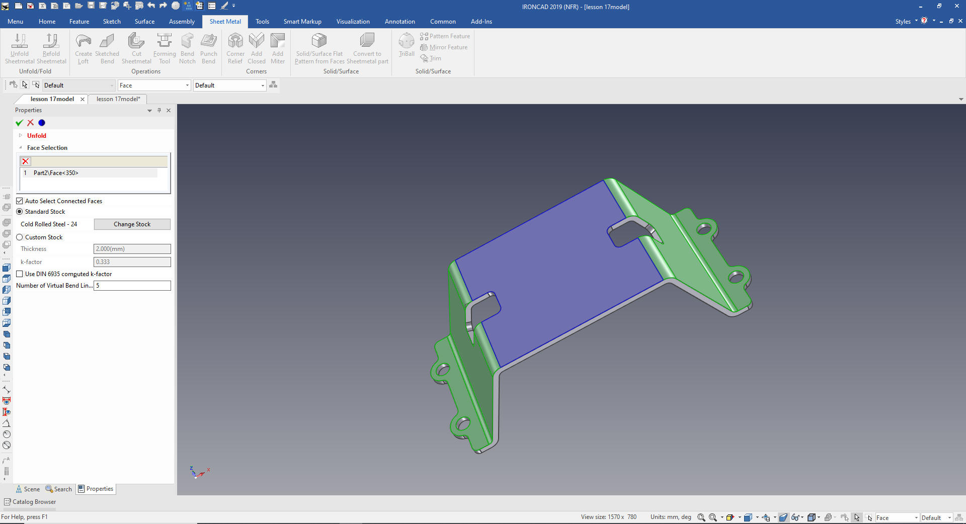
pattern. But IronCAD will unfold any correctly designed model.
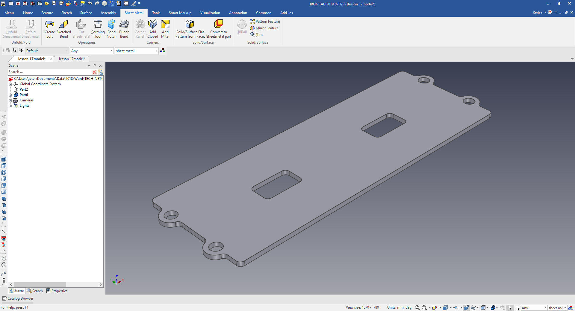
We select the base face.
Here is the flat pattern model.
We have to create a configuration call sheet metal to create the
AID.
We suppress the original part and now we can create the flat
pattern AID.
The unfolded flat pattern
So there you go. That is how we
modeled sheet metal parts in the past and I still do.
It is
very important that you look into how you or your engineers are
creating the parts. Streamline Sketching and Feature Based Modeling
is easy to learn and implement. It, alone, will increase
productivity 10X. Now, IronCAD with its unique integrated
history/direct edit functionality can increase your productivity
another 5X or more with changes! Again, time is money in
engineering.
More on Streamline Sketching and Feature
Based Modeling.
To experience this increased level of productivity, please download
IronCAD for a 30 day evaluation. Legacy data is no problem, IronCAD
can read the native files of all of the popular programs. IronCAD is
a great replacement for the subscription only Autodesk and PTC
products.
Give me a call if you have any
questions. I can set up a skype or gotomeeting to show this part
or answer any of your questions on the operation of IronCAD. It
truly is the very best conceptual 3D CAD system.

 Now
Now