|
All You Wanted to Know About Drawing to 3D Conversions 
There are very few people that know more about 3D CAD than I do.
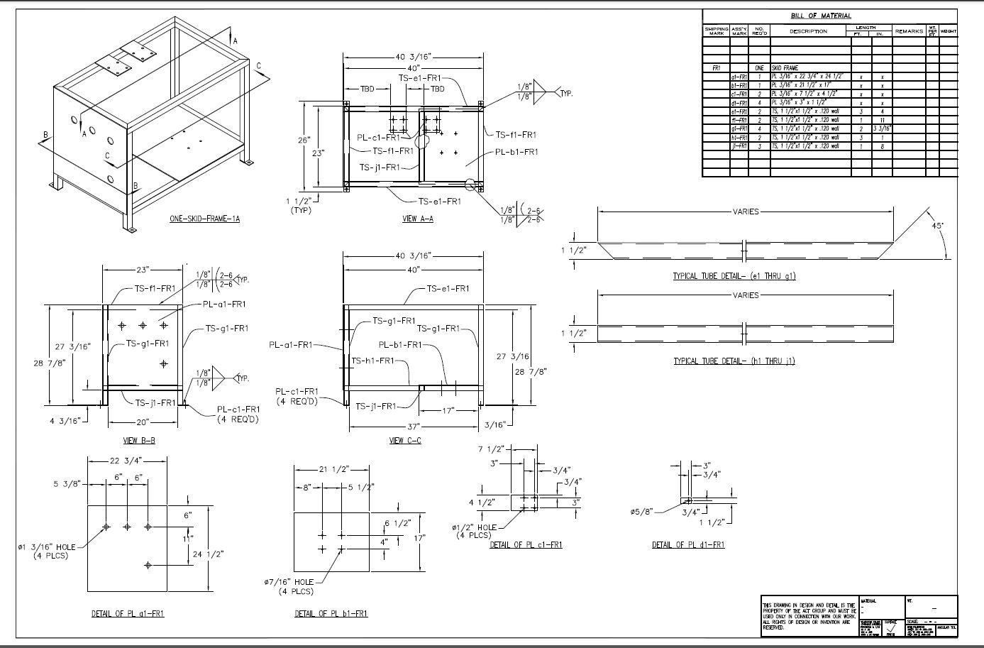
The 1980's - 3D CAD - The Beginning There were no drawing conversions in the beginning, from about 1982 to 1988, due to the selling point of 3D CAD was faster drawings. Now, of course, these were not drawings. Actually, there was no name for them at the time, the Boeing draftsmen called them the "Flat File". They were plotted on vellum treated like drawings and released as blueprints. It was around 1988 and surfacing was introduced to CADKEY, with an add-on called Fastsurf. Things changes. The 3D model could now be used for more than just basis for the drawing. The 3D model could now be used for CNC. This was the beginning of MBE. The model now was delivered to manufacturing as an IGES file to use as a pattern. They were delivering the model along with the blueprint. The Death of the Drawing I had a great business turning drawings, manual or electronic, into 3D models. I even was turning 3D wireframe into net surfaced parts. This went on until 1995 with the introduction of solid modeling on the PC. The 1990's - 3D CAD/CAM Moves to the PC!! With electronic drawings, mostly from AutoCAD, we had two options. Use the drawing or utilize the 2D graphics provided by the .dxf. Many of us are still taking .dxf or now .dwg and creating the 3D models. .dxf was a bit of a faux translator since it was controlled by Autodesk. While the graphics came over great the dimensions and annotation left a lot to be desired. Here is a simple example of a .dwg conversion in IronCAD. This will give good idea how this works. Complex part take a bit more work but it is worth it in many cases. But again you have to check the model to the original drawings. Autocad drawings are notorious for not being correct. IronCAD is the only program that provides CAXA a standalone Autocad clone or association with the 3D modeler. This provides a high level of compatibility with the .dwg. Creating a 3D part from a Autocad drawing Here is a bevel gear created from a .dwg in ZW3D. This shows you a level of complication that 2D graphics can provide in a 3D conversion. This is a good example of how drawings to 3D conversions can be used for 3D CAD training. Convert 2D Data to 3D Models Many machine shops will not take drawings anymore. In the past the CNC programmer was skilled in 3D CAD and was part of his/her job to do these conversions. I sold Boeing and every Boeing supplier a seat of CADKEY, IronCAD or ZW3D. They would not only convert the drawing but they could tweak the 3D model when necessary. All of these programs offer robust direct edit functionality. Checking, Design Review, Manufacturing and Data Extraction! I took a contract to turn two torpedo propellers into 3D models, because the Navy couldn't find a shop that would take the job. These were drawings that were drawn 10x showing the section cuts of the blades. Not a hard job, but one that takes the skill of a pattern maker. Rule number one! The goal is to have a 3D model that matched the drawing. There is only one way to check the job. You have to re-detail the part. There are no short cuts. How do you re-detail the part? We do not draw drawings today since we are creating 3D models I have a very good example that I did to show an IronCAD prospect how much faster they could design in 3D and produce documentation. From Drawing Based to 3D Based Example Some may have been stuck in Autocad making drawings. But none were still on the board. A while ago, I gave a presentation of IronCAD to a company that was still using Autocad to make drawings. They built welded assemblies and did not design any machine parts and were satisfied with creating drawings since they were basically doing fabrication component design. I actually created the frame assembly in front of them in less than an hour and created the AID's (Associated Information Document) including an ISO view of the assembly within minutes. Showing them the speed of solid modeling and document creation. Remember when the model was revised so was the AID. Here is the original .dwg. I did not use the .dwg graphics in creating the model. It was made of square tubing and I just created one tube and copied and pasted them into position and pulled them to the correct length and trimmed if required. The other were plates that I could pull to match the other structure.
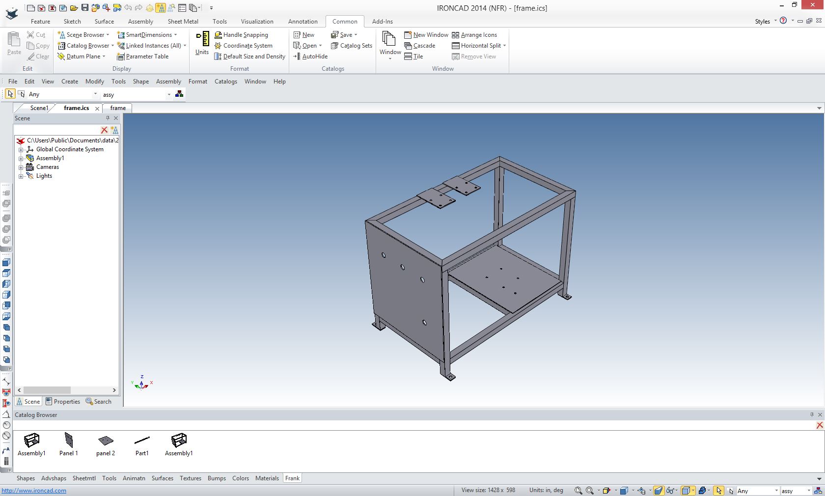
Here is the assembly created in IronCAD. Notice we created a custom catalog (bottom) with some of the common parts.
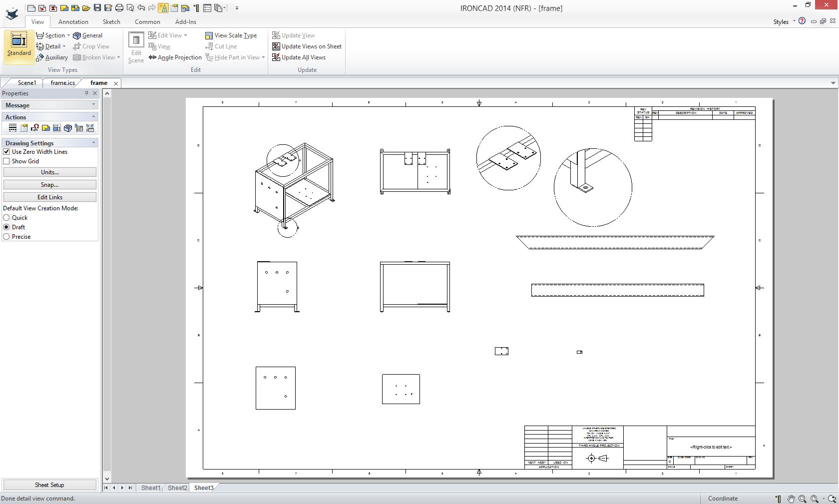
Here is the assembly AID sans dimensions and parts list defined in minutes
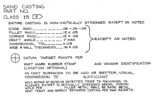
A Drawing to 3D Conversion Failure! I was hired to do an evaluation of a machined part from an old customer and associate working for a large machine shop. He called and said a large airplane company sent them a drawing and the 3D modeler was finding cavities in the part. This was after two weeks of modeling in Catia 5. They needed the 3D model to do the CNC programing and then machine it. I am not sure if the company has a contract with these folks to convert the drawing and provide the Catia model or just deliver the final part. You have to wonder if the large aircraft company would inspect it or leave that to the supplier. I assure you all standards are out the window. I asked if it was a sand casting and he didn't know. One look at the drawing.
The drawing consisted of the sand casting and the machining of the casting. No one questioned these two separate definitions? This large aircraft company is a leader in Model Based Enterprise! The model is the design authority!
Can the 3D Model Be Used as the Design Authority? Why in the world are they sending out drawings? You would think the company would have a department with a "Standard Process" dedicated to convert drawings to 3D models in Catia to assure they were meeting the model as the design authority. I am sure this would be a great place to put the millennial engineer to get familiar with the products components.
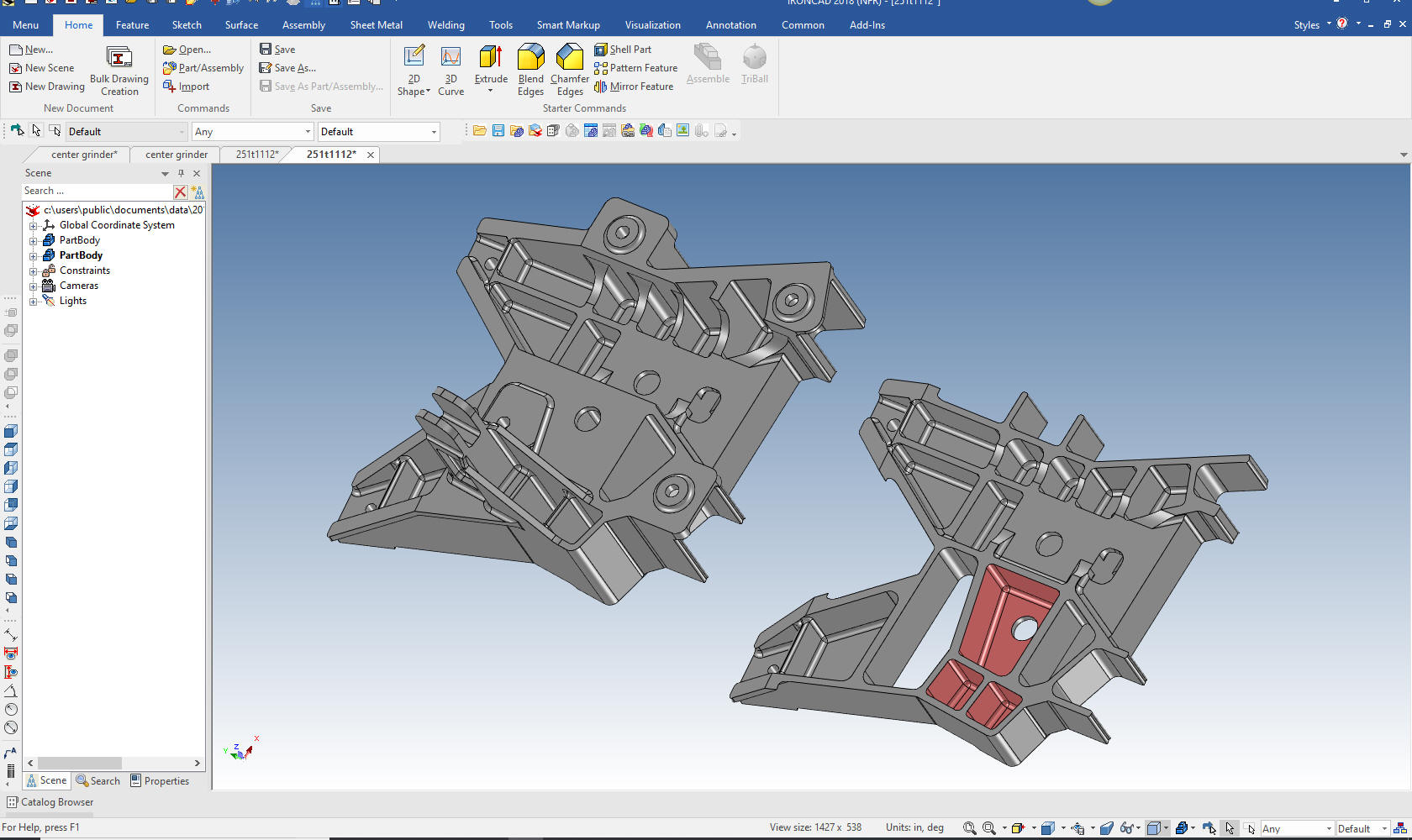
This level of irresponsibility of a company It is interesting that the supplier is now required to provide the model. But at what cost? This two day model turned into weeks, maybe months? Now they have to provide the model, which I saw was done incorrectly. First, they have to check that the model matches the drawing, which it doesn't, then they have to inspect to the model. Uh, who is in charge of this mess. Why does this company depend on the supplier to provide the 3D model in Catia? We can only speculate. But again I note, that they obviously have no standard processes in place. Using the native Catia 5 file, I imported the model in IronCAD and found the cavities. You can see them here in the sectioned view on the right. But I also instantly saw the part was done incorrectly. The errors stood out like a sore thumb. You have to go through a thorough checking when you convert drawings to 3D models. So two weeks already spent. Corrections another week. Checking another week. How many more hours will it take? It took me less than 30 minutes to define the problem. If you need a checker or an highly experienced design draftsman, give me a call!
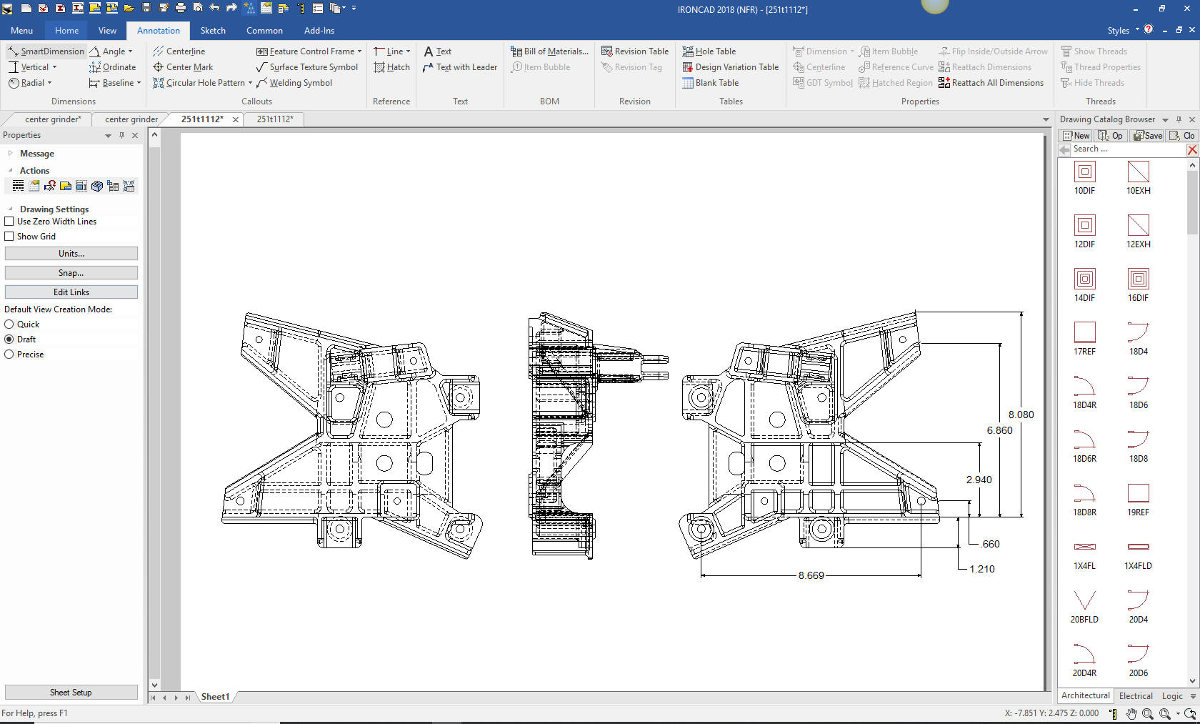
Drawing conversions are much different than designing parts. You have to re-detail the part exactly to check it. There are no short cuts. Murphy is looking play a big part in this process. This was a sand casting and came with basically two drawings in one. The casting drawing and the machined drawing from the casting. So you would model the casting first, then the machining. This would be simple in IronCAD or ZW3D since both parts could coexist in the same file. My first thought is how would they do this in PMI. If there is anyone out there doing this please give me a call and show me what the PMI looks like. This would probably take two PMI's to replace the single drawing. Where with an AID it would easily be defined. Here is an AID (drawing) checking the part with just a few dimensions I found a serious modeling error. You can see this is a very complex part. When you do drawing to 3D conversion you "have" to detail it. That is the only way to assure you have duplicated the part.
Here is an articles that brings this problem to the forefront. I have seen articles by PLM gurus that say it is too hard for an engineer to read a drawing. He is an BSME that has never did one drawing, 3D model or AID. It is hard for him to read a drawng. Yes, all Boeing airplanes from the 767 down are based on drawings. Where would they get the personnel to convert the drawings to parts. Would they contract them out like they did with the above part and lose control of the integrity of the parts. In 1986 I did a pilot project to see how CADKEY could do 3D modeling and documentation in the 747 Flight Deck group. In those days the product was a plot of the AID on paper. We would have to put in an order to get the print back. We delivered the AID in the form of HPGL plotting format. When we released the engineering it would be as an HPGL and it would be printed on Mylar and released into the system the same as a drawing. CADKEY was an instant success and Flight Deck proceeded to order 45 seats of CADKEY and eliminate one of the three Catia 3 seats. You would think with this obvious success that Boeing would have selected CADKEY, which they had 1500+ as their 3D CAD system. Remember CADKEY was already on the PC. Nope, they opted for Catia and never realized the benefits of the PC until the turn of the century. CADKEY or Catia? Boeing’s Billion-Dollar 3D CAD Mistake! The use of Drawing to 3D Conversions for Engineering Training. Today's millennial engineers do not know how to read a drawing. In this world of CNC the machine shop only use the AID (drawing) for reference so even the CNC programmer may not know how to read a drawing. But we still need to create AIDs for fabrications that do not require CNC or inseparable assemblies like weldments and sheet metal assemblies. How do we cure this problem? We truly need to train anyone coming into engineering classic drafting.
After a brief introduction to manual drafting, Drawing to 3D conversion is one of the best ways to train fit, form and function design and 3D CAD. It kills two bird with one stone. Each drawing is an example a level of design. I suppose we should have an assembly showing the relationship of the parts for tolerancing. Also different disciplines, machine, sheet metal and plastics. The would also train Millennial engineer what a drawing represents. So if you are an academic or engineering manager, you may want to look at this solution. Learning on the job will always be a part of the engineering education. But it would be nice to have the basics out of the way. All the above rules for the conversion should also be applied to training. Stay tuned I feel a training manual coming!
Give me a call if you would like to discuss this subject.
The Death of the Draftsman or
We sell and support IronCAD and ZW3D Products and provide engineering services throughout the USA and Canada!
If you are interested in adding professional hybrid modeling capabilities or looking for a new solution to increase your productivity, take some time to download a fully functional 30 day evaluation and play with these packages. Feel free to give me a call if you have any questions or would like an on-line presentation. For more information or to download IronCAD or ZW3D Joe Brouwer206-842-0360 |
|
HOME | ABOUT | PRODUCTS | SEMINARS | TRAINING | TECH-NET NEWS
TECH-NET ASSOCIATES | RENDERING OF THE MONTH | CAD•CAM SERVICES
HARDWARE | TECH TIPS | EMPLOYMENT | CONTACT