These articles started out as
product comparisons, but quickly turned into a study in 3D modeling
techniques.
When I introduce IronCAD's very
flexible design paradigm I have a hard time to get the Pro/e clone
users, like Solidworks and other programs to understand the drag and
drop design paradigm.
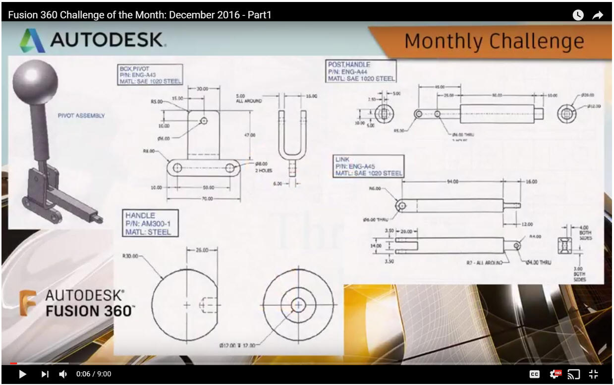
I saw the
following video challenges on linkedin and thought I would give it a
try on IronCAD. This will give you an idea how different
and flexible IronCAD is compared to the conventional Pro/e clone and
to the not so conventional Fusion 360.
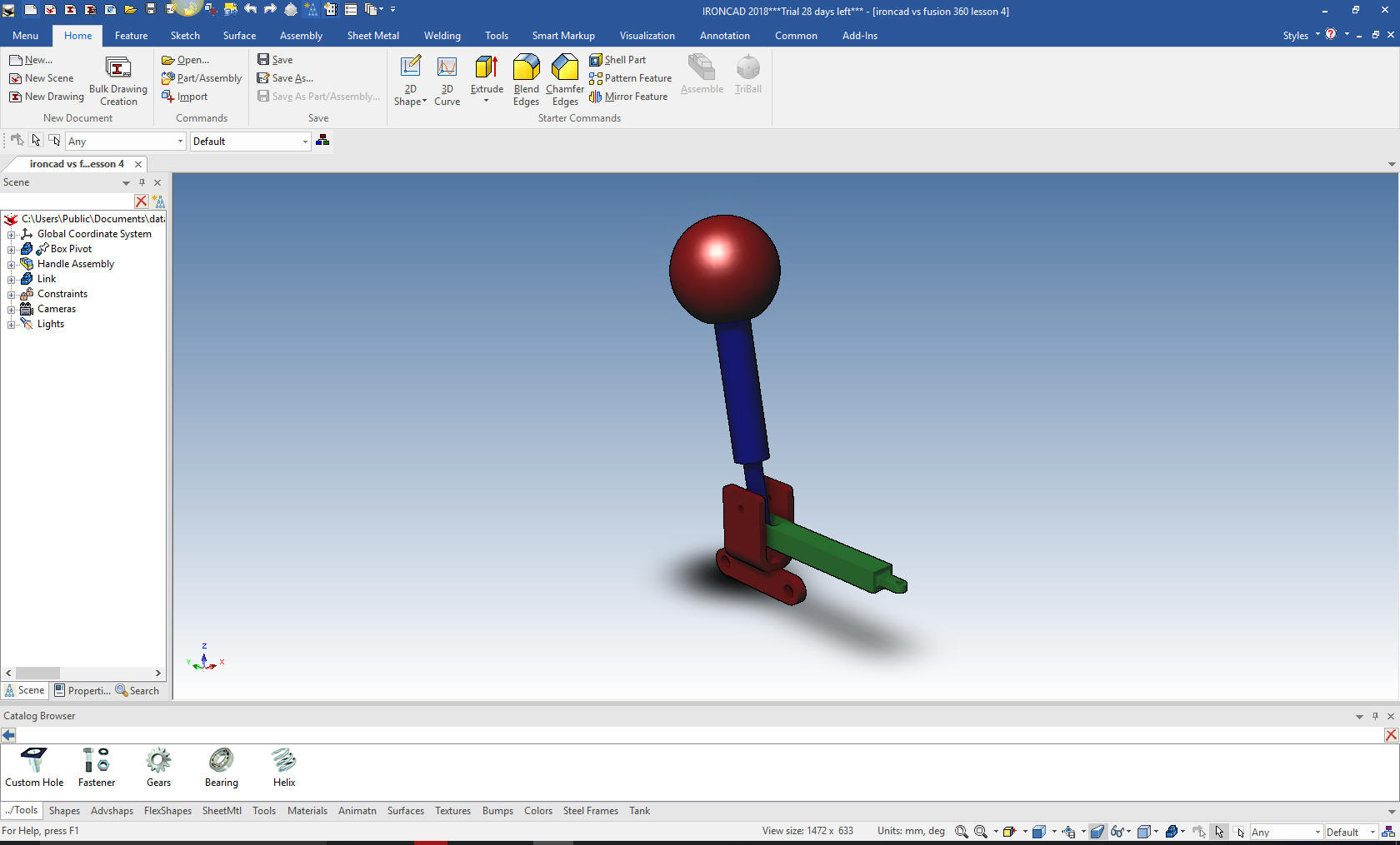
Here is the Drawing
Assembly is the very
best feature of IronCAD. With its true single model environment it
offers the highest level of productivity. Watch how we use drag
and drop with a minimum of sketching to complete this job in no
time. There is no better program that can manipulate parts and an
assemblies in a 3D space.
While creating 3D models from a drawing is the very best
way to learn 3D CAD and maybe some design techniques is does not
expose the designer to the design flexibility necessary in product
design. IronCAD is all top down due to the single model environment.
Creating mating parts is a cruise. But modeling is just one aspect of a
well designed productive 3D CAD system.
IronCAD vs Fusion 360
I would do a
video, but I really am not good at it. So I will show you step by
step. I will try and get IronCAD support to create one. They are
very good.
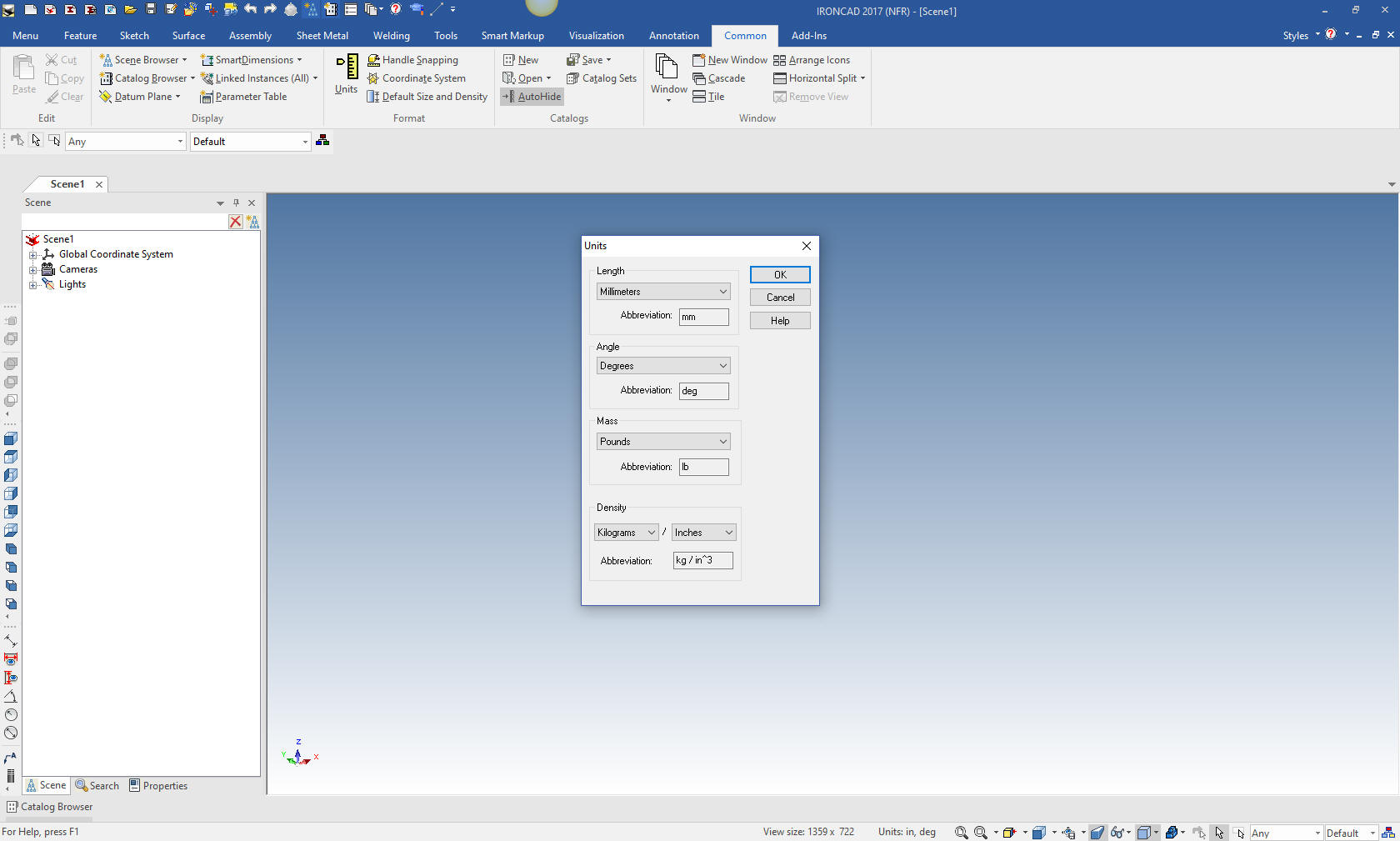
Here is IronCAD. We set the units to
millimeters.
I have to admit
that the Fusion 360 presenter made this part incredibly complicated.
If this is the way 3D CAD design is being done, we are wasting
thousands of engineering hours.
Even though IronCAD is very
easy and fast, Fusion 360 could be used much, much more effectively
with feature based design. It looks like many are stuck in this
wasteful sketch, sketch, constrain, constrain world. Even when the
system offers more productive options, they seem to stick with this
convoluted level of design. I had a Solidworks user try IronCAD. He
whined "I cannot sketch like I am used to". I just shook my head and
thought: "He is stuck in an archaic (1988) 3D CAD design Paradigm."
This is mostly design technique, not so much IronCAD. While we
extensively use drag and drop design the basic functionality of this
design process is in all systems.
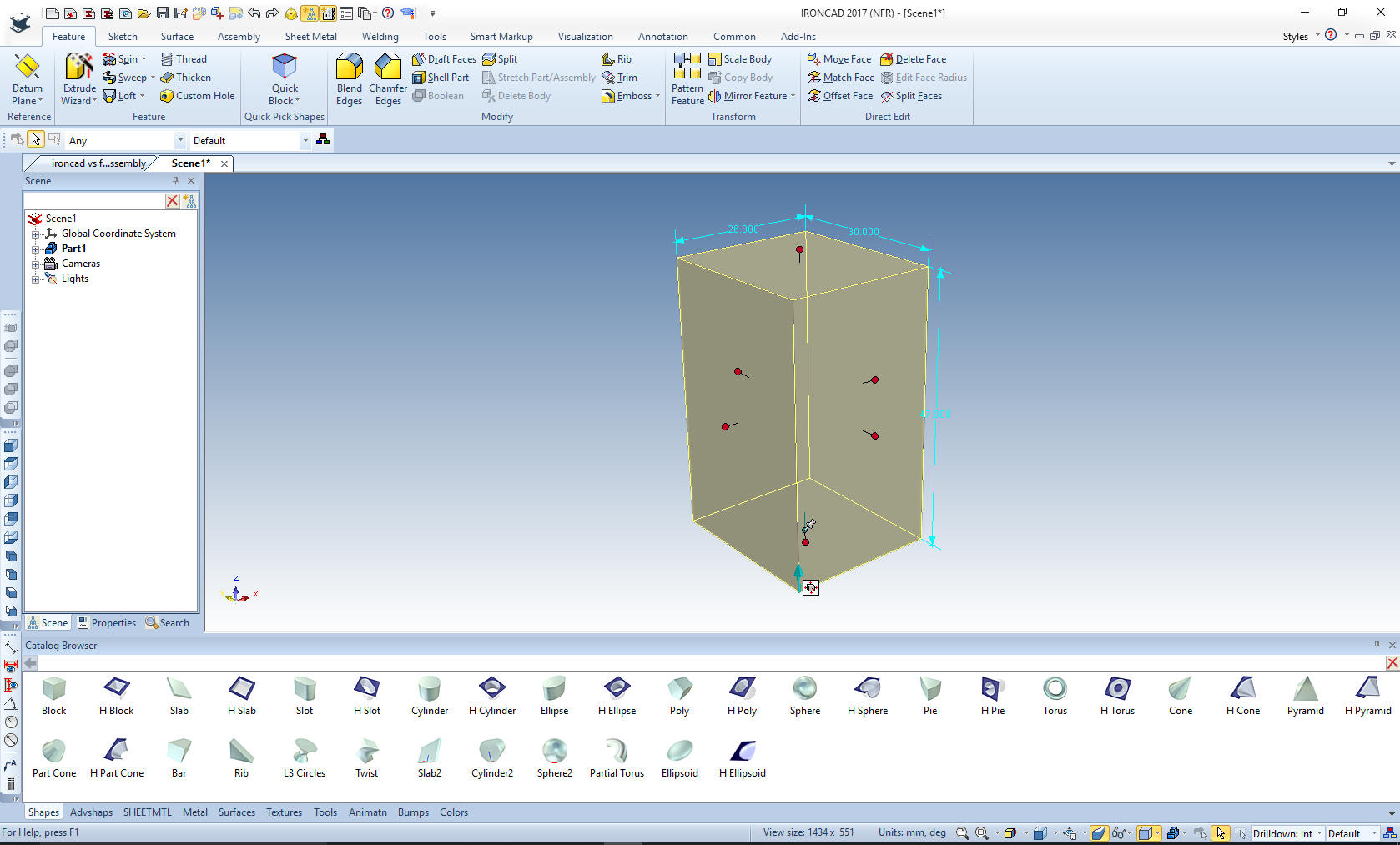
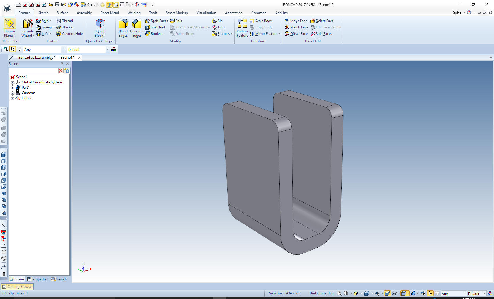
Let's start with the "Box
Pivot" We drag a
block from the standard shape catalog into the scene and size it.
This part is so
simple that it strains all credulity to watch how the Fusion 360
fellow modeled it. We will put in the two blends and shell the part.
That's it.
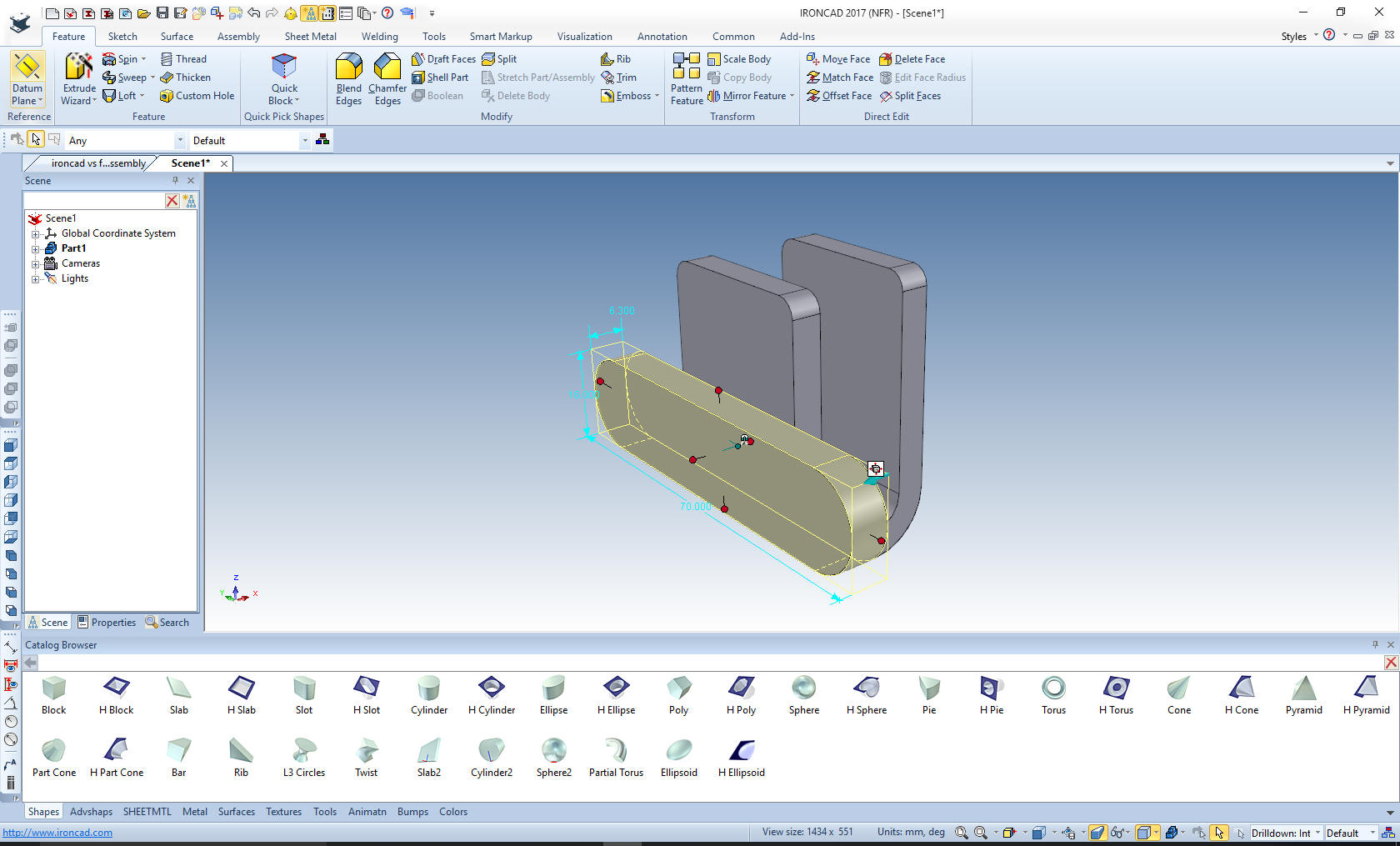
Now for the
support. We drag a slot shape from the standard shape catalog on the
to face of the yoke and size it. You learn quick with IronCAD how to
drag and drop the parts to make them most usable.
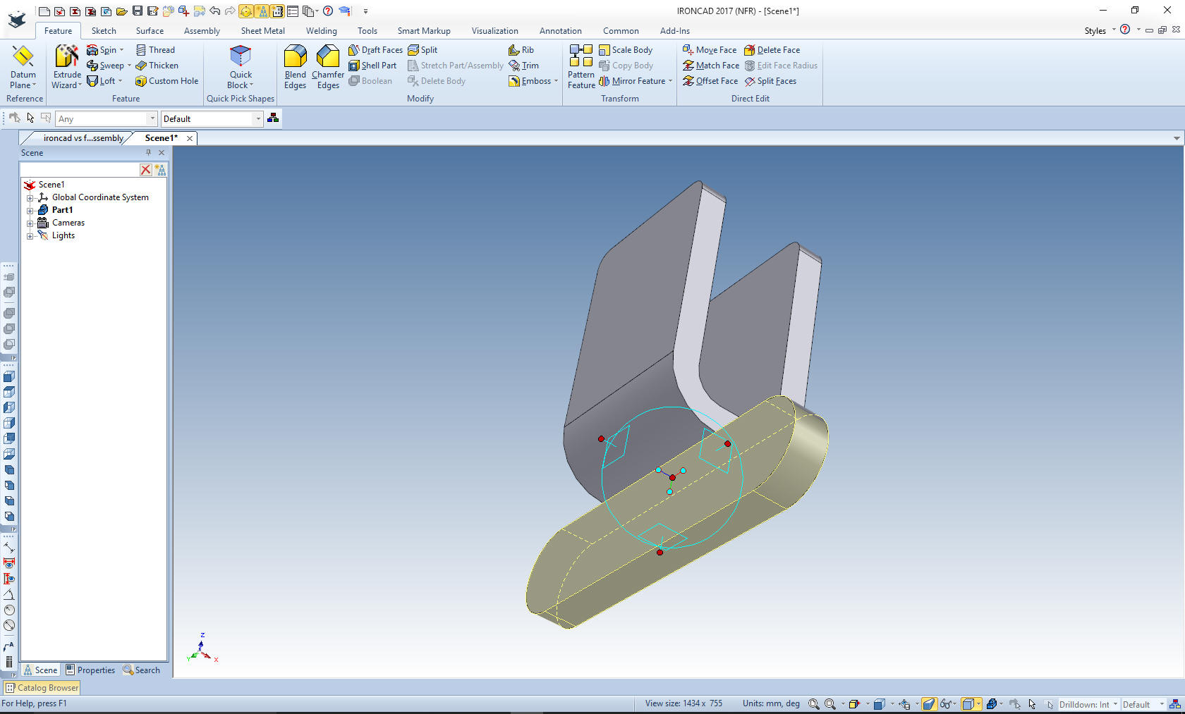
Using
the Triball we locate in middle of the top face of the shape. You
can locate the Triball at set defined points, edges, ends, centers
and in this case the middle of the face.
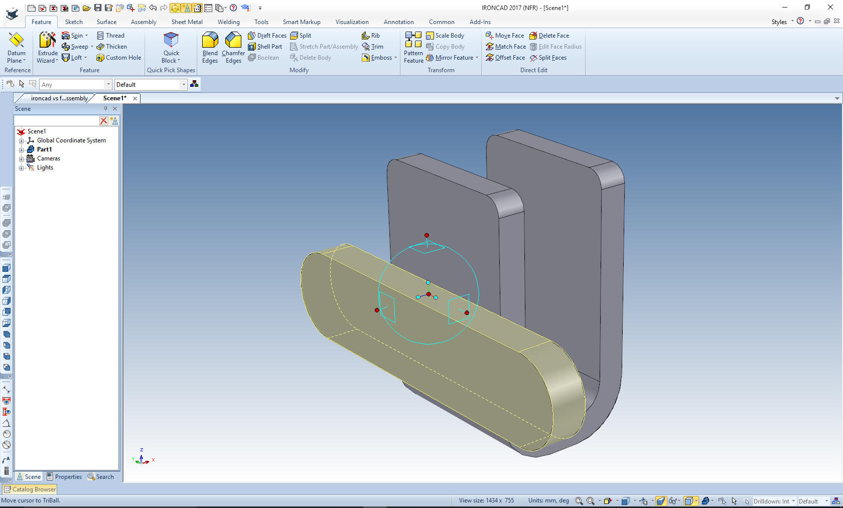
We just place it on the middle face of the
bottom of the yoke.
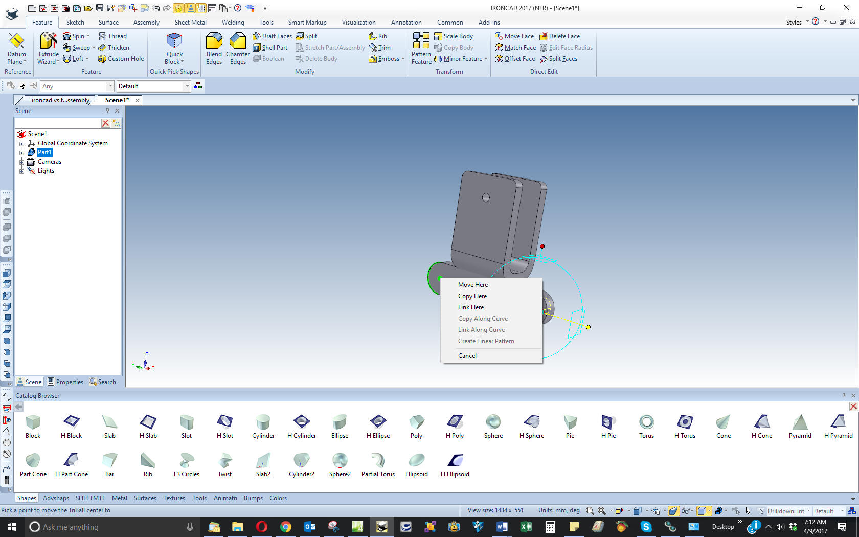
Now we drag the
holes on the the part. After we create the first bottom hole we use
the triball to drag it to the other location and link it. Linking is
the way to create associated copies of the feature, part or
assembly. With features you can edit one and all will change. The
same goes with parts or assemblies, but they also get recorded as
the amount of the multiple parts and sub-assemblies in the parts
list.
We are done. Nope,
again, not one sketch. We will lock the Box Pivot in its location.
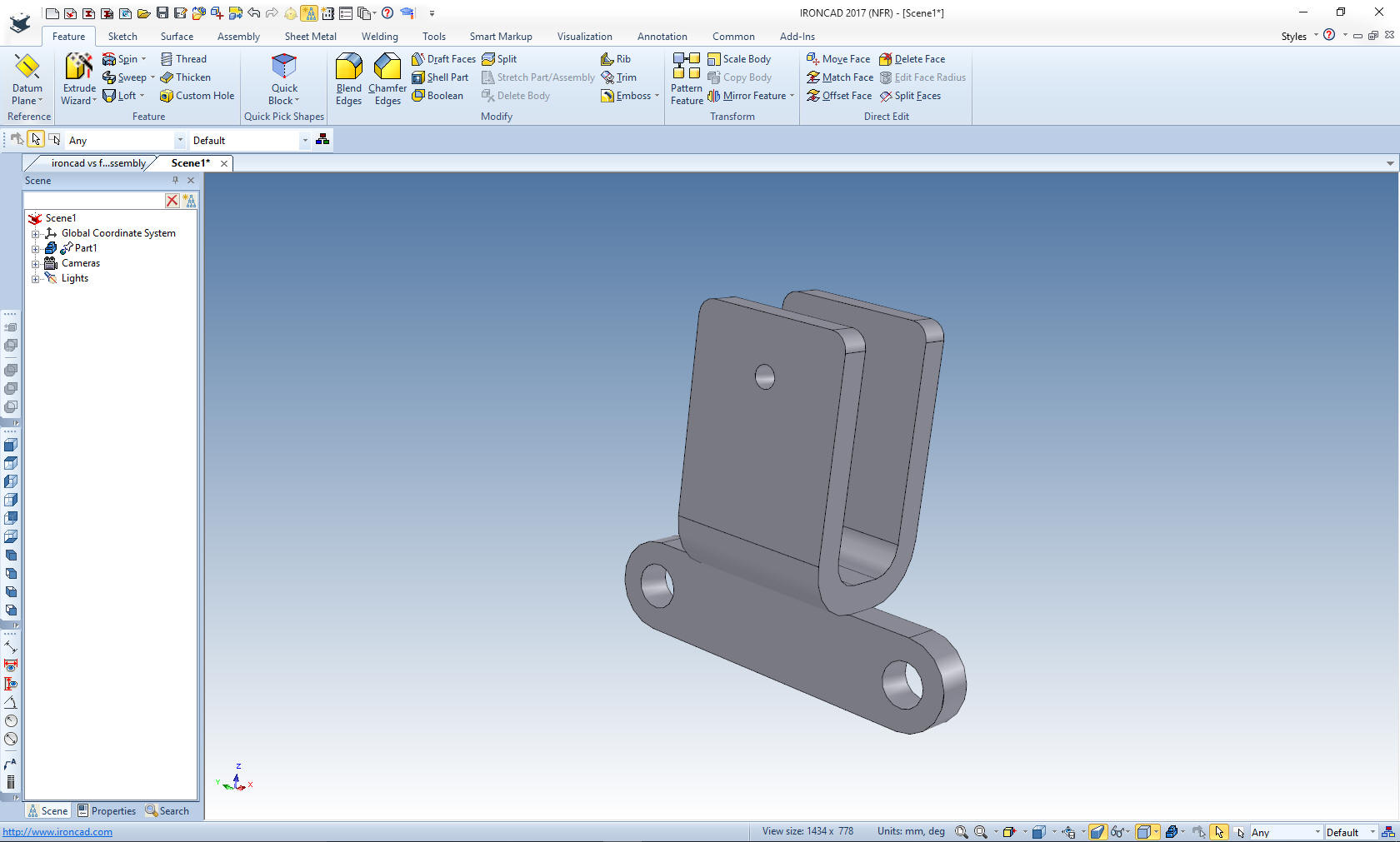
I
will do this in context, by designing the parts in location. We will
start with the "Post Handle"
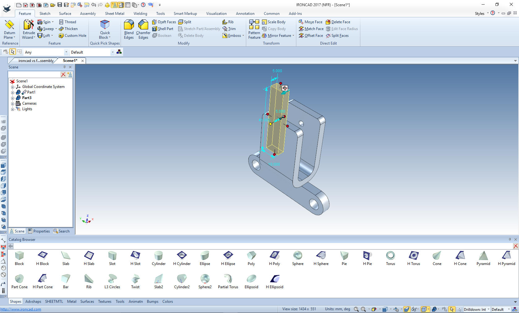
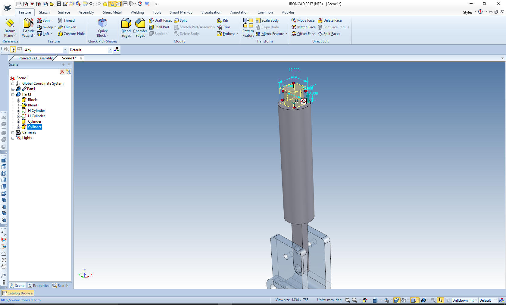
We drag another block on to the
face of the Box Pivot, just to keep it in close proximity, by using
the right mouse button that allows us to create a new part (notice
the different color). We locate the block on the top edge and size
it.
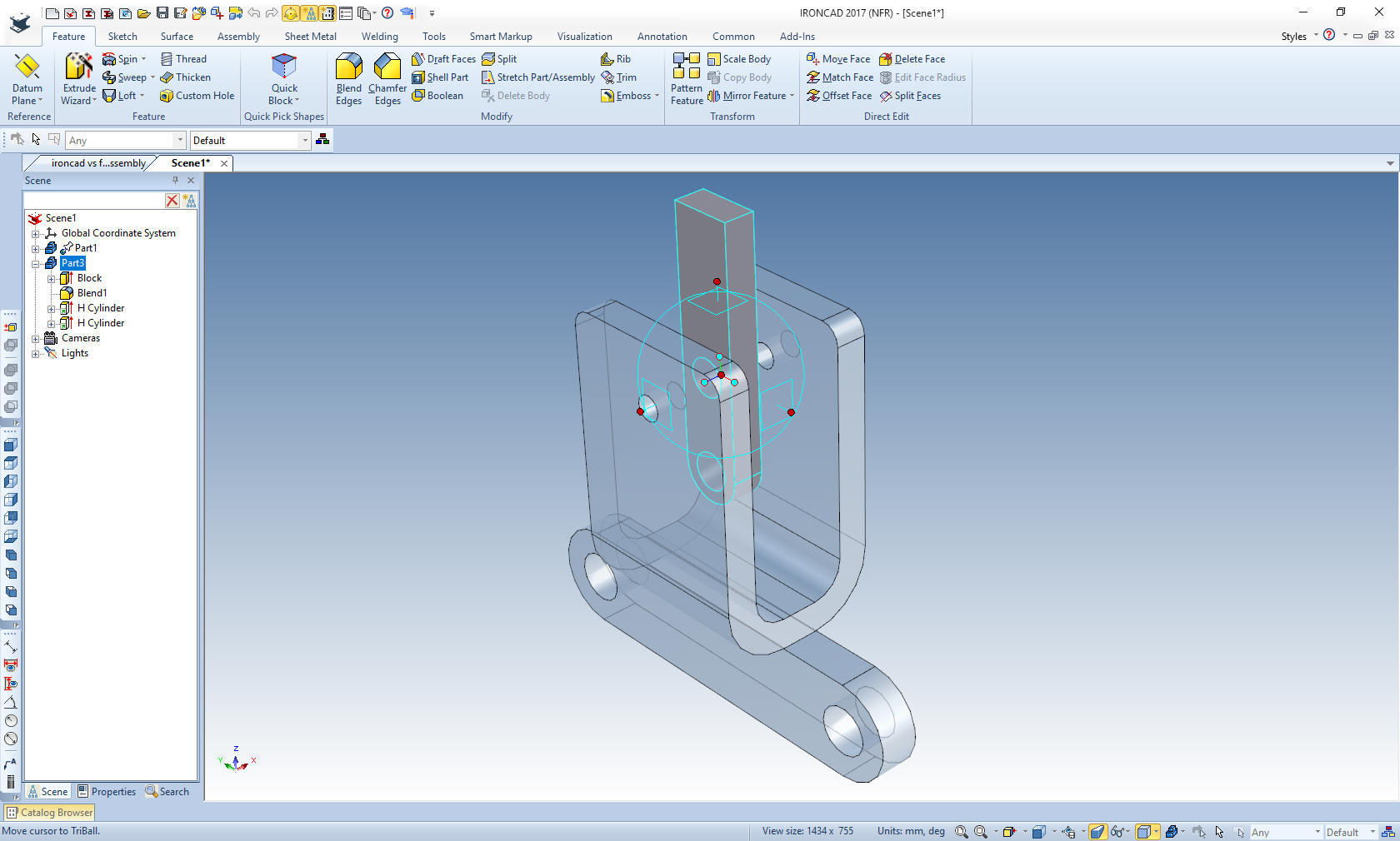
We will add the
blends and holes. With a few moves with the triball we locate the
shape. I made the Box Pivot transparent to see the shape more
clearly.
I will
now add the rod and the boss to the shape. I just drag two cylinders
out of the standard catalog.
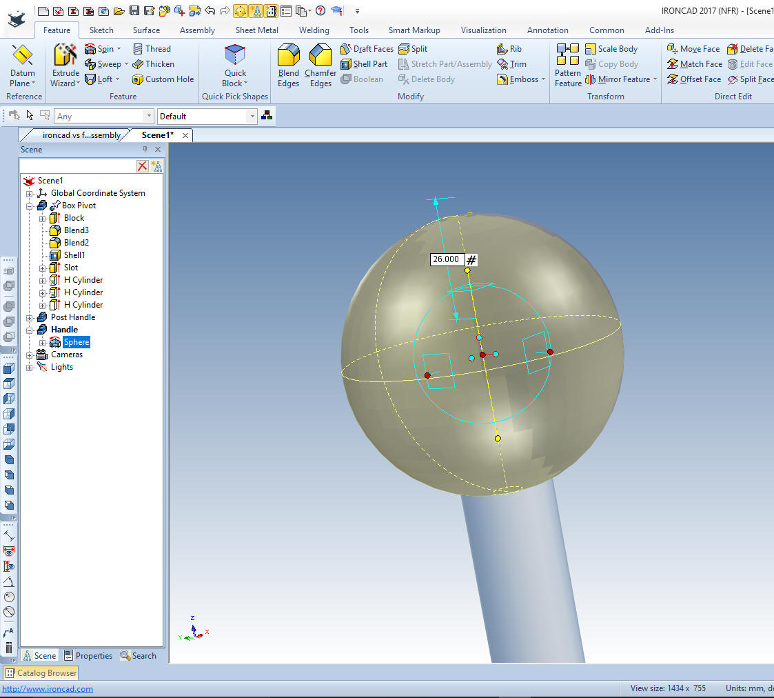
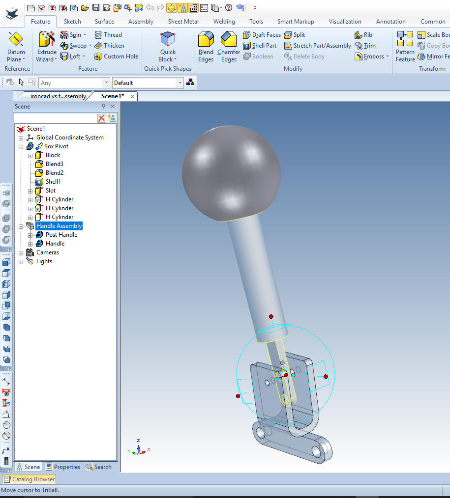
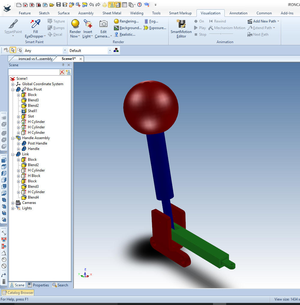
We are
done with the Post handle. Now for the handle. Again we drag a
sphere from the catalog and located it on the top of the lower
cylinder and size it by just editing one of the handles. I also move
it up 26mm to the correct location. I have changed the color of the
Post Handle show that it is a new part. I have also renamed the
parts. All parts are designed in a true single model environment.
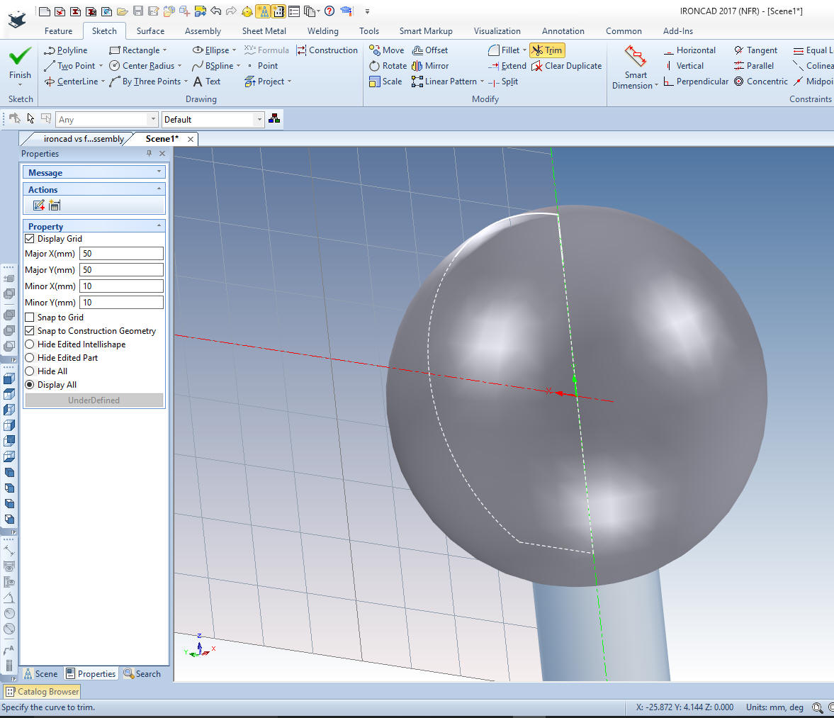
Okay, I am going to edit the sketch that the sphere is based. Even
IronCAD, has to do "some" sketching. I just create line and
trim the sphere. I could have created the hole in the sketch, but I
just dragged a hole cylinder to the center of face. It is just much
easier if I need to edit the hole later. Remember each shape
positive or negative is based on a sketch.
We select okay and we are done with
the handle. But we will now bring the Post Handle and the Handle
together as the Handle assembly. This will us to treat this as one
assembly when we move it.
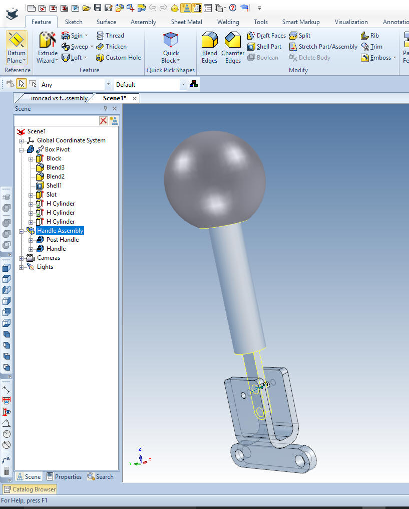
We
will rotate the handle assembly a bit to duplicate the original
Fusion 360 picture above before we start the link
Now we
will drop a block from the standard catalog on the face of the Box
Pivot with the right button and create a new part and size it. We
add the blends and drag a new whole block for the cut and size it.
The catalog is automatically hidden to provide more design space.
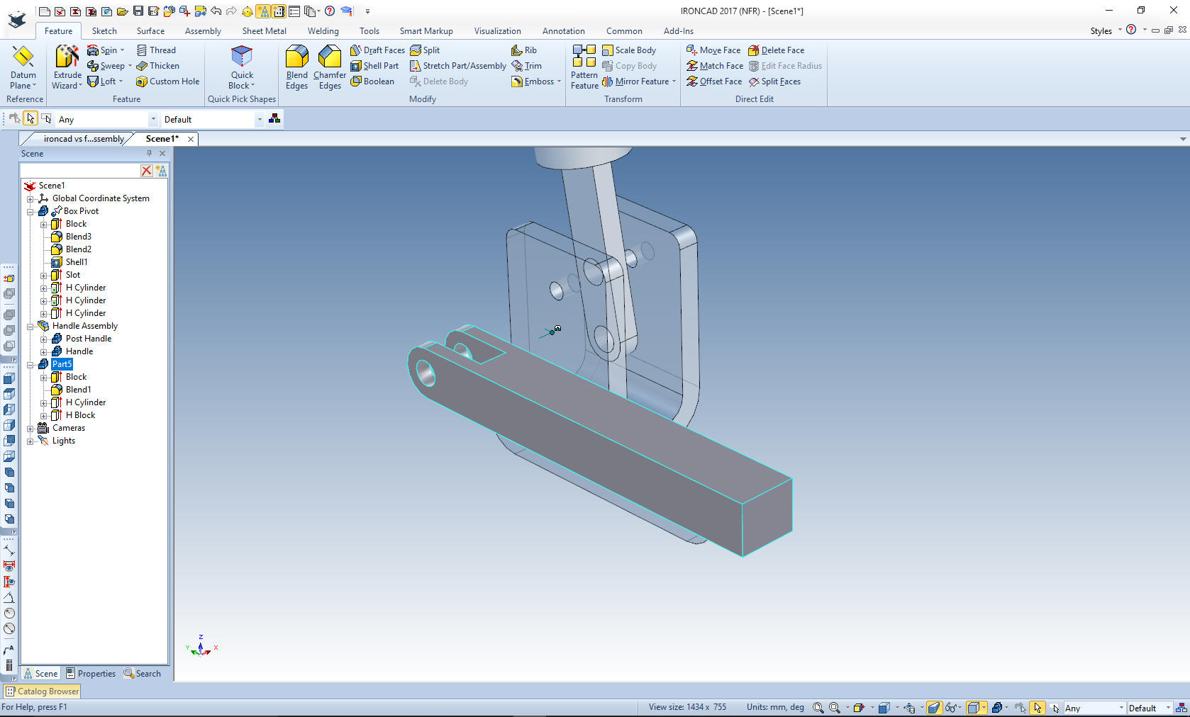
We
locate the bock and add the shape at the end.
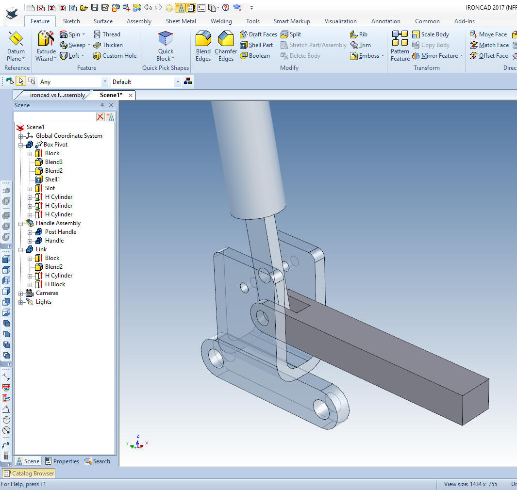
We
drag a block to the end of the link size it an create the blends and
the hole, add the last blends.
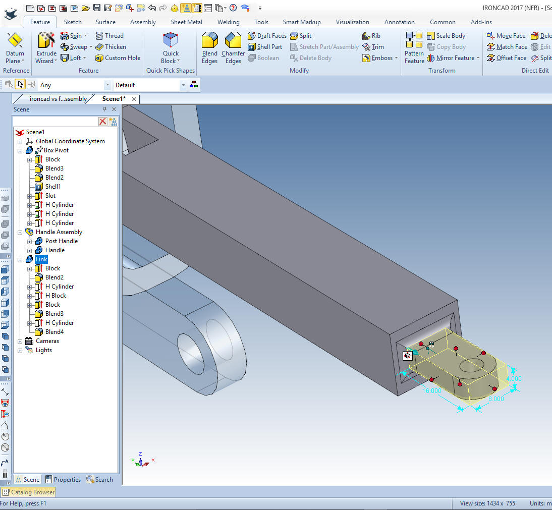
We are
done. One sketch!! If you watch all of the parts being made by the
Fusion 360 fellow you can see all of the time wasted on sketching
and constraining. Yes, time is money, but it is also so much grunt
work. IronCAD is easily 5x more productive in conceptual design and
10x more productive on changes.
It is
very important that you look into how you or your engineers are
creating the parts. Streamline Sketching and Feature Based Modeling
is easy to learn and implement. It, alone, will increase
productivity 10X. Now, IronCAD with its unique integrated
history/direct edit functionality can increase your productivity
another 5X or more with changes! Again, time is money in
engineering.
More on Streamline Sketching and Feature
Based Modeling.
3D CAD Modeling Techniques
To experience this increased level of productivity, please download
IronCAD for a 30 day evaluation. Legacy data is no problem, IronCAD
can read the native files of all of the popular programs. IronCAD is
a great replacement for the subscription only Autodesk and PTC
products.
For more
information or to download IronCAD
Give me a call if you have any
questions. I can set up a skype or gotomeeting to show this part
or answer any of your questions on the operation of IronCAD. It
truly is the very best conceptual 3D CAD system.
TECH-NET Engineering Services! |