3D Modeling Techniques
IRONCAD vs Solidworks Lesson Six
Streamlined Sketching/Feature Based Modeling
When I introduce IronCAD's very
flexible design paradigm I have a hard time to get the Pro/e clone
users, like Solidworks to understand the drag and
drop design paradigm.
I have created
fourteen
"IronCAD vs
Fusion 360" lessons to show the difference between IronCAD
and Fusion 360. These lesson are a study in modeling techniques.
I found the Fusion 360 presenter was wasting massive amounts of time
with overly complex constrained sketching procedures. I was
incredibly unimpressed. Look at my highly productive proven modeling techniques plus IronCAD's
superb design system.
I was quite pleased to have found these exercises from a
Solidworks dealer and thought I would show the difference in my
modeling technique plus the highly productive modeling method
offered by IronCAD. I again find modeling techniques that can easily
be streamlined even within their existing system. I call it
Streamlined Sketching and Feature Based Modeling. Please review a few of the above IronCAD vs Fusion 360
lessons, there are more very stark differences.
While creating 3D models from drawing is the very best
way to learn 3D CAD and maybe some design techniques it does not
expose the designer to the design flexibility necessary in design. IronCAD is all top down due to the single model environment.
Creating mating parts is a cruise. But modeling is just one aspect of a
well designed productive 3D CAD system.
Solidworks
is a marginal 3D CAD system based on the dated Pro/e (Creo) history
based modeling system. I have sold this product years ago and found
it, like all of the other Solidworks clones, not productive enough
for our engineering department. We use what we sell. That gives us
the experience to effectively support our user base.
I would do a
video, but I really am not good at it. So I will show you step by
step. I will try and get IronCAD support to create one. They are
very good.
As with my Ironcad vs Fusion 360 exercises
I have found the same problems with Solidworks. The modeling
technique is hugely responsible for the level of productivity. Those
of you that are only trained in the complex and time consuming
constrained sketching world are truly limited by not using the freedom of
Streamlined Sketching and Feature Based Modeling, that is available in even the most
Solidworks-ish of CAD systems. If your
designers are designing in these very unproductive and time
consuming processes it might be time to review your standard design
processes. Don't have any do you?
Let's get started!
I could do this model a bit more
productive but I want to start it without too much design intent
study to shows some interesting features in IronCAD. It is obvious
you would start with the cup since you have to shell it. But you will see
Streamlined Sketching and Feature Based modeling is much more
productive and flexible. It gives you a more real world feel to
your design process and is a much more pleasurable and productive experience.
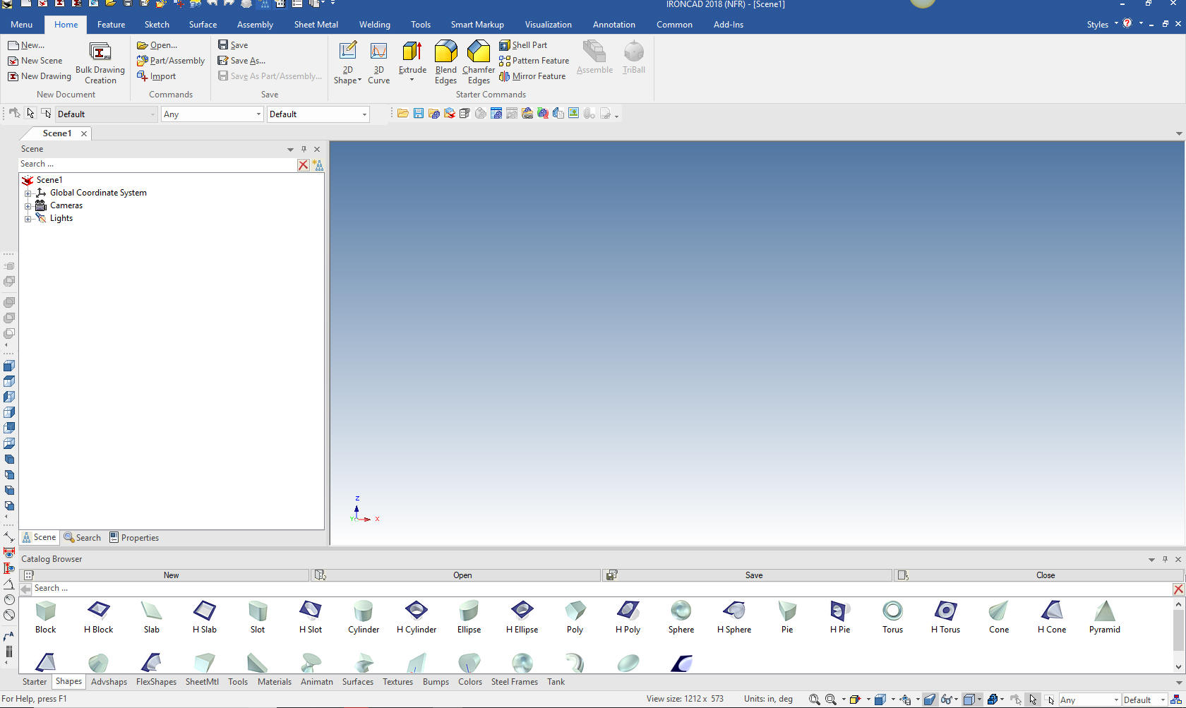
We are set the units to millimeters.
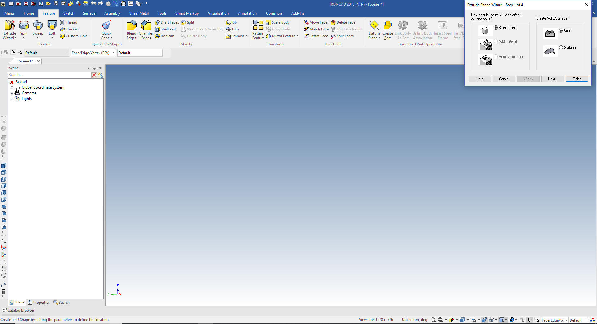
We select the
"Extrude Wizard" to create our first extrusion. We will model this
part much differently how many of you were taught by the constrained
sketch based systems.
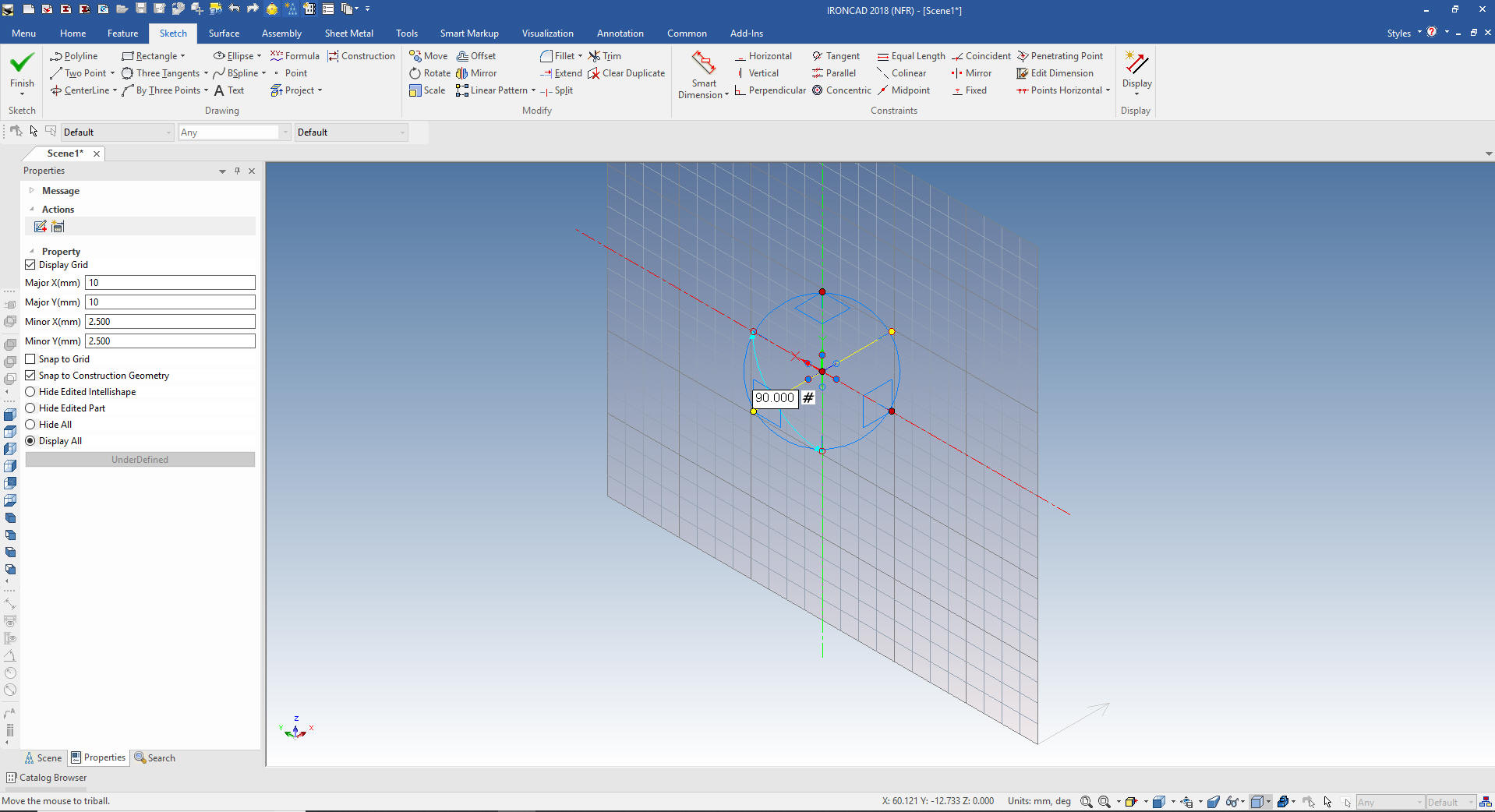
We set the depth at 15mm
Using the Triball we orient the sketch plane to work in the view we
want. Notice at the bottom right the direction of the extrusion
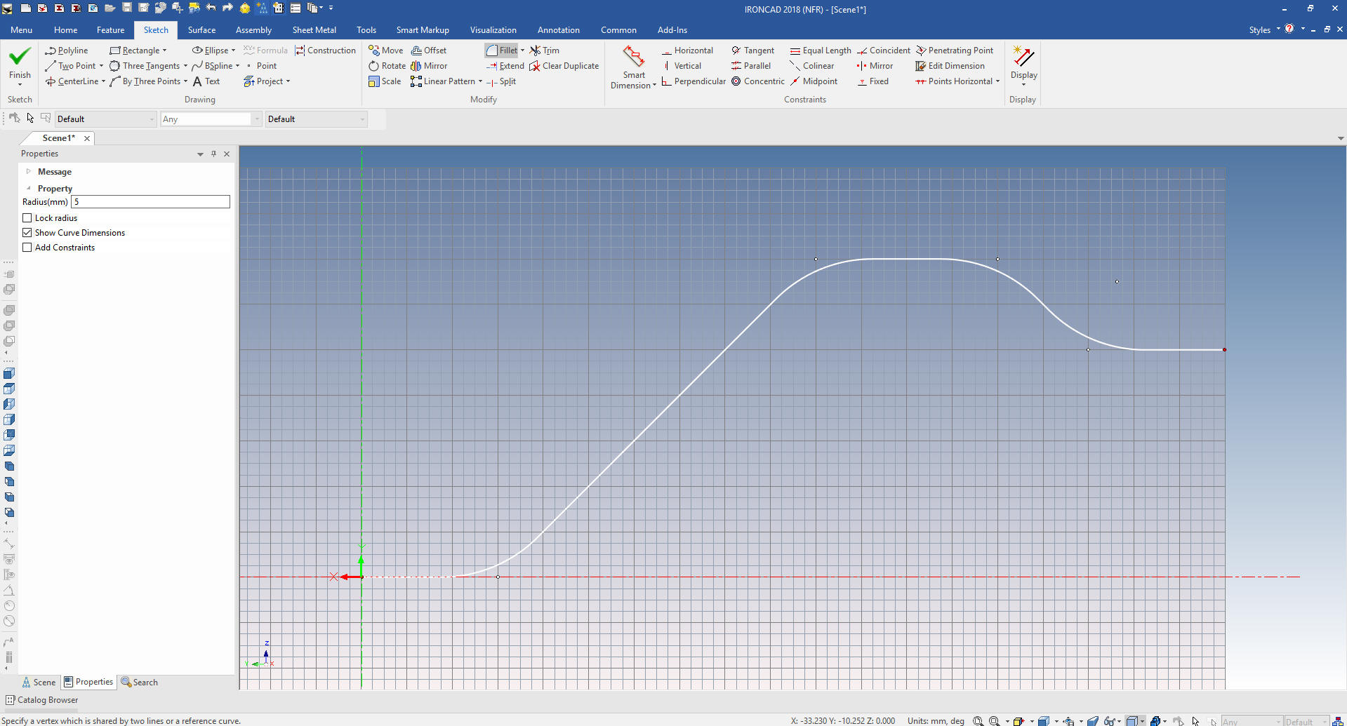
We turn off the Triball by hitting the
Esc key and look into the sketch plane. Sketching in IronCAD is
similar to any other CAD package. We create the handle contour
without and constrained or any dimensions.
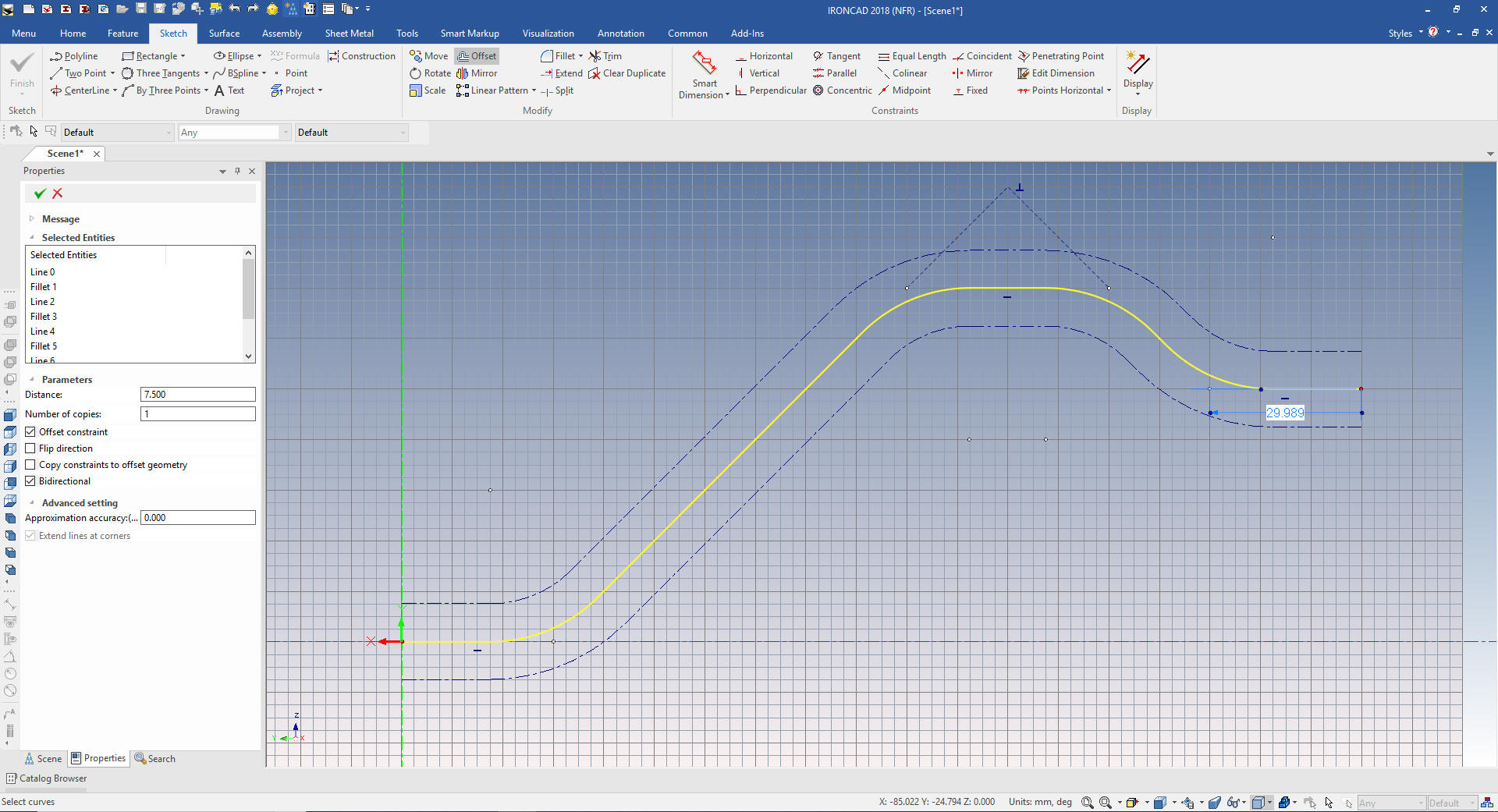
We offset the contour by 7.5 mm bidirectionally.
We can just hit the delete key to delete
the original contour and connect the ends and select okay and we
have our basic shape of our handle. We select iso view to see the
results.
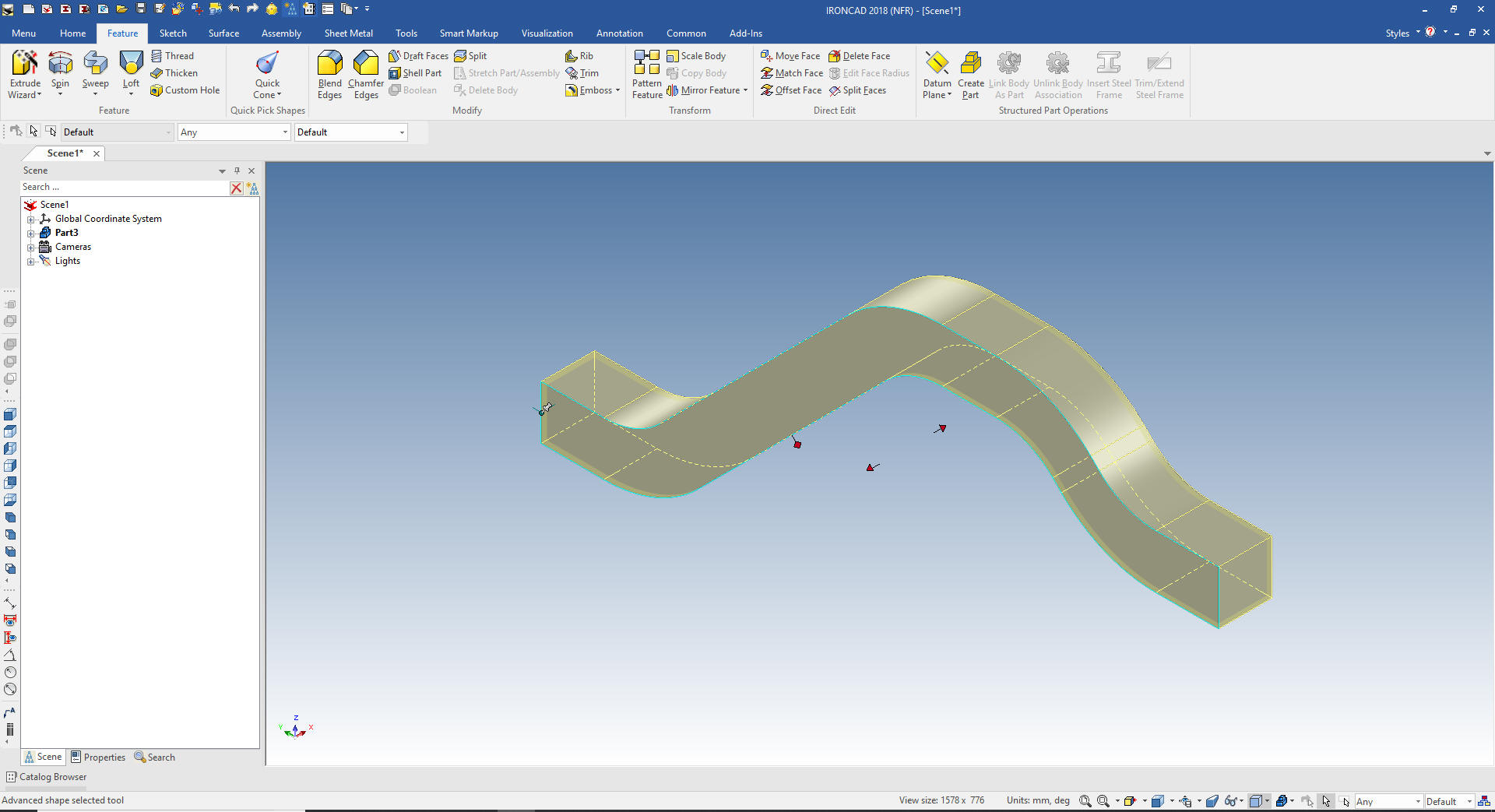
We
will leave it in the iso view for the next step of the inside cut.
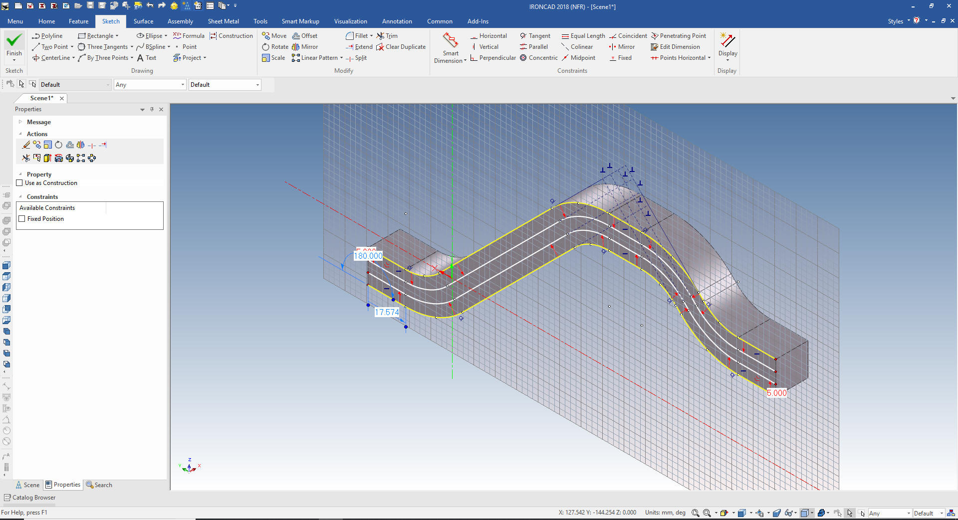
Using the Extrude Wizard we select the depth to 5mm and select the
front face for the sketching plane. We will project the complete
face and delete the end lines. We will offset the outside lines 5
mm.
Since the outside lines are highlighted we
can just hit the delete key to delete them. Add the end lines and we
select okay creating our cut.
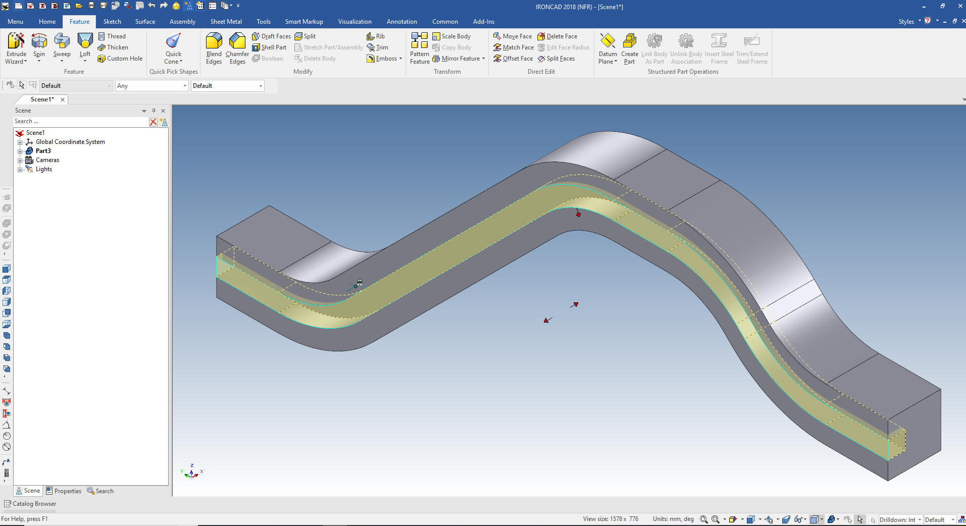
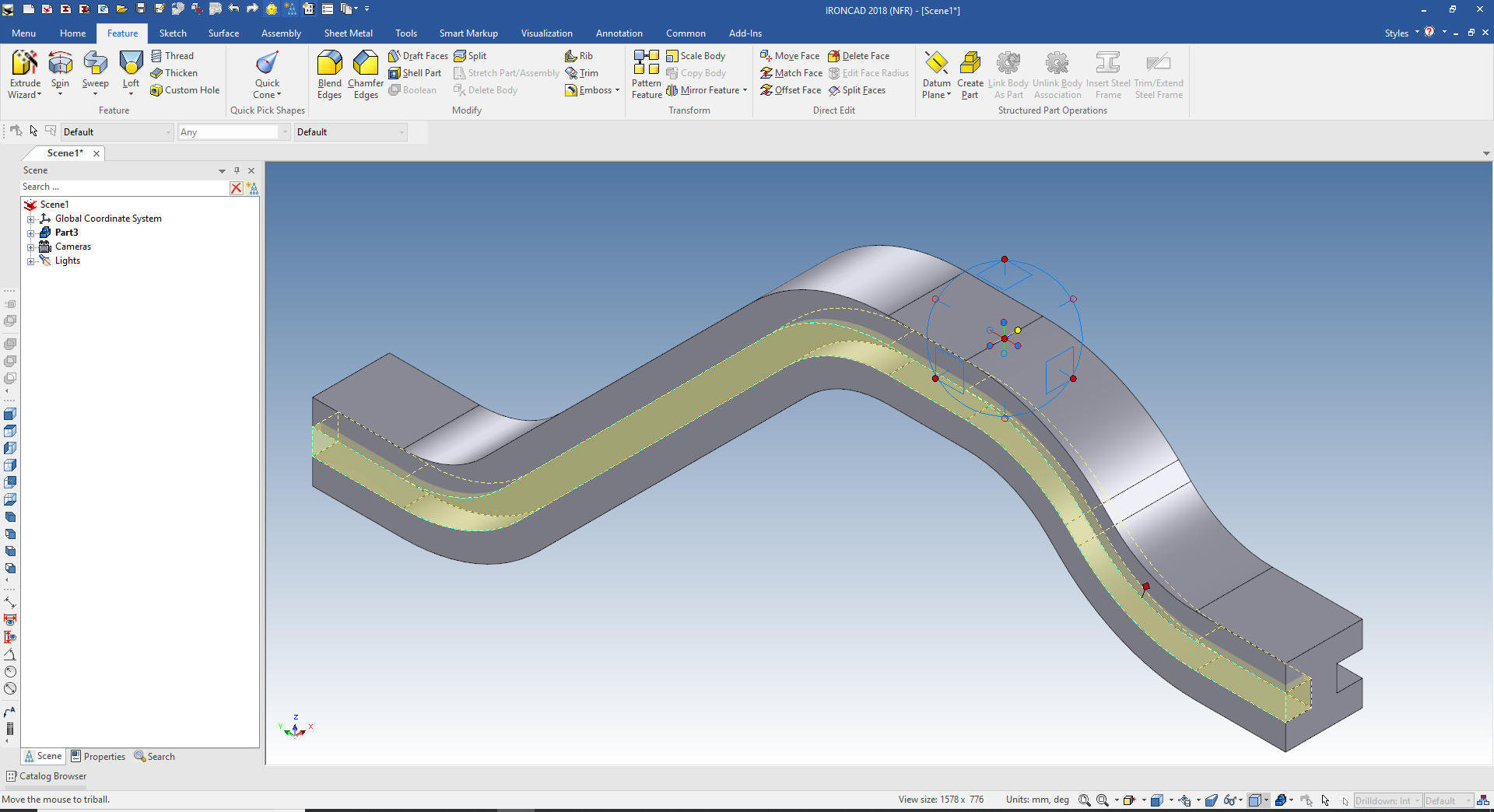
We
locate the Triball to the mid-point of any edge to mirror link the
new feature and we are done with our basic shape of the handle.
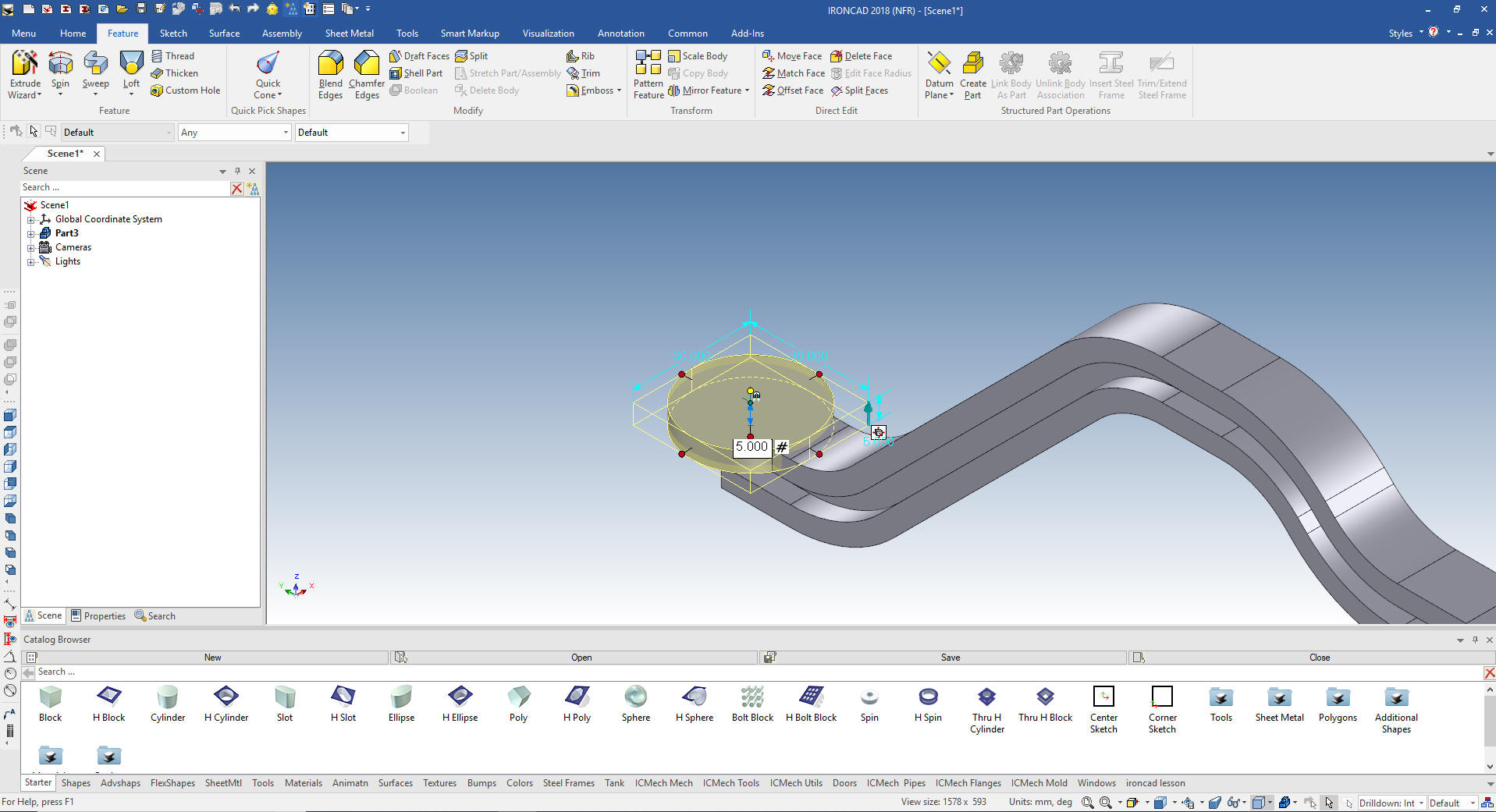
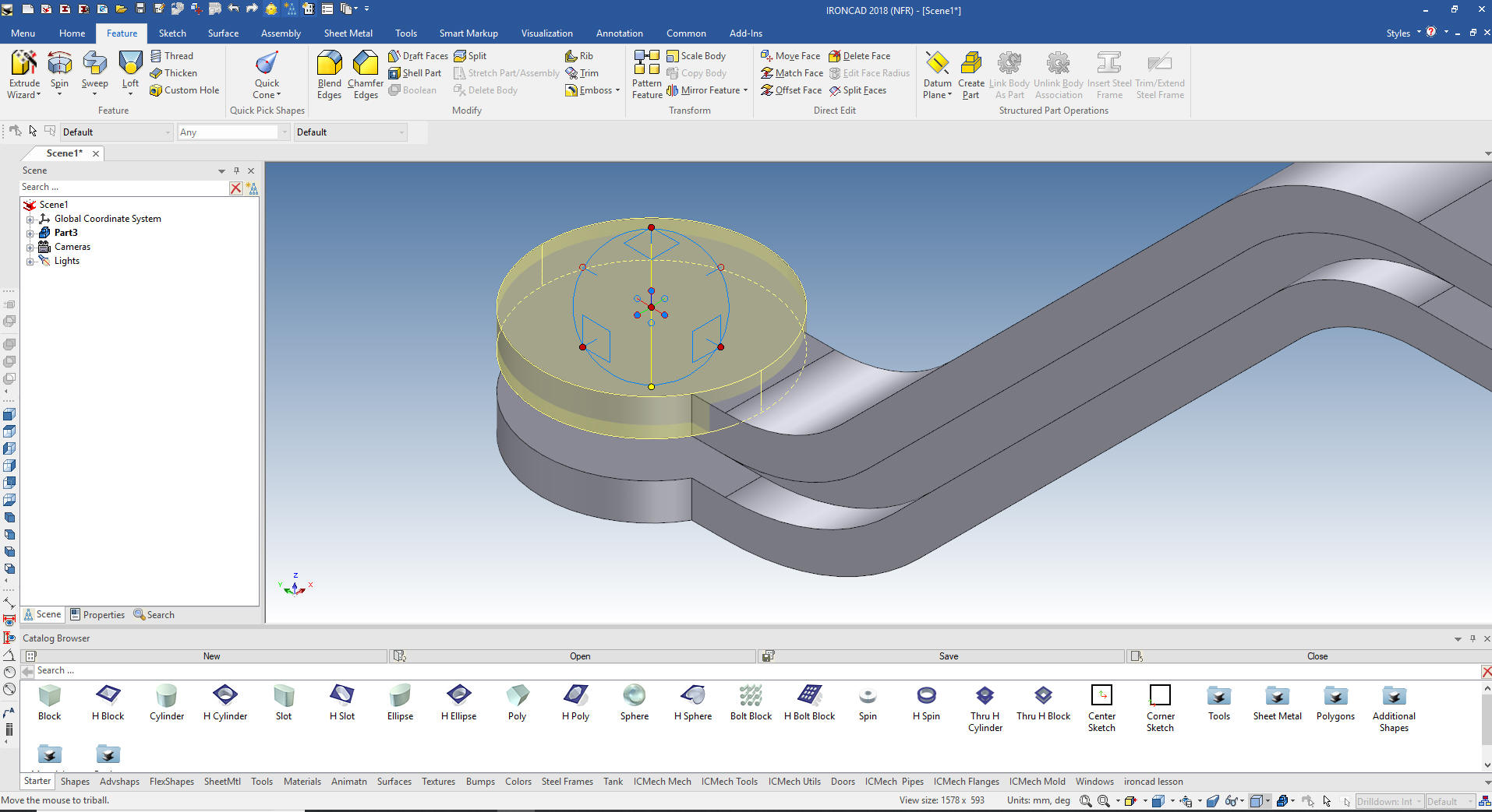
For the left side feature we turn
on the catalog browser and select a cylinder. We orient the view so
the cylinder recognizes the view necessary to use an edge for
placement. We drag and drop a cylinder on the edge and size it.
This is the second time I have seen a user first in Creo and now
in Solidworks to create cylindrical shapes with a revolve tool. I
suppose this is the fastest way in a sketch only based system but it
seems so strange to me. I suppose I could do this with sketches only
to see, but this exercise it for showing a different modeling
techneque.
Again using the Triball we just create a linked copy on the
bottom.
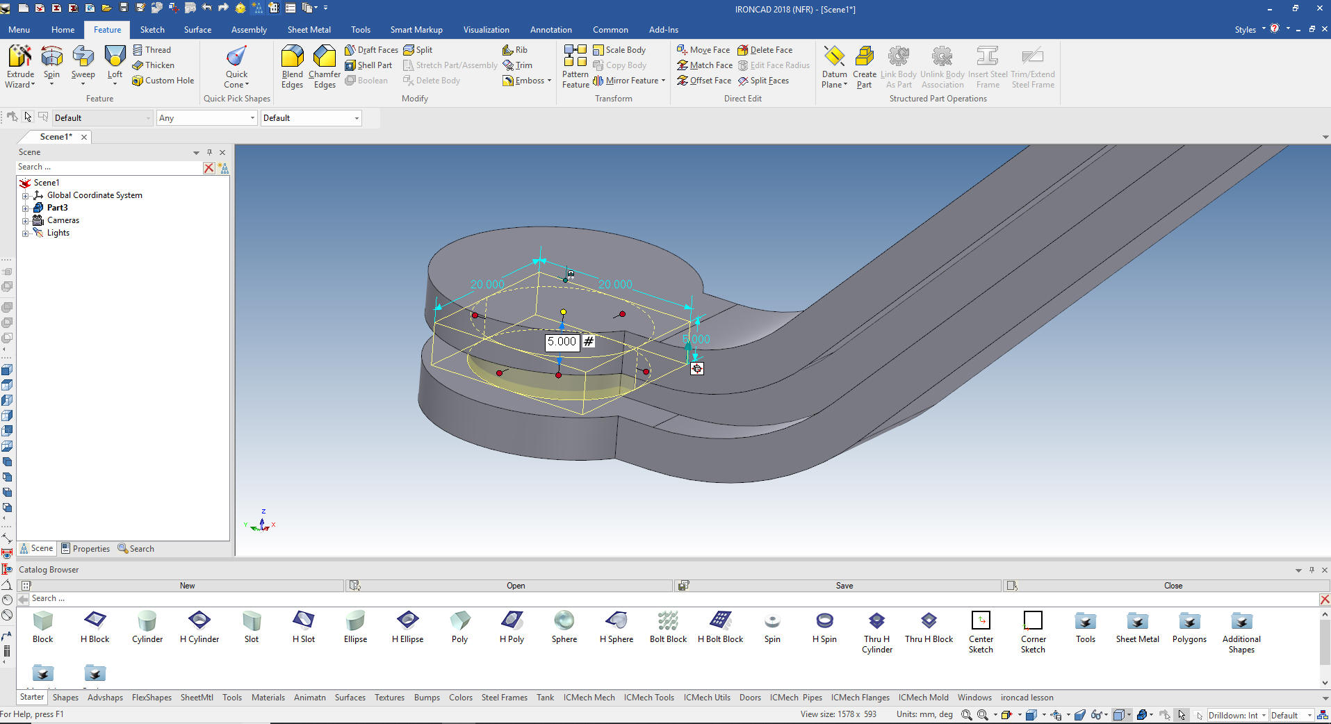
We just drag and drop another cylinder to the center of the top
cylinder for the center cylinder and size it.
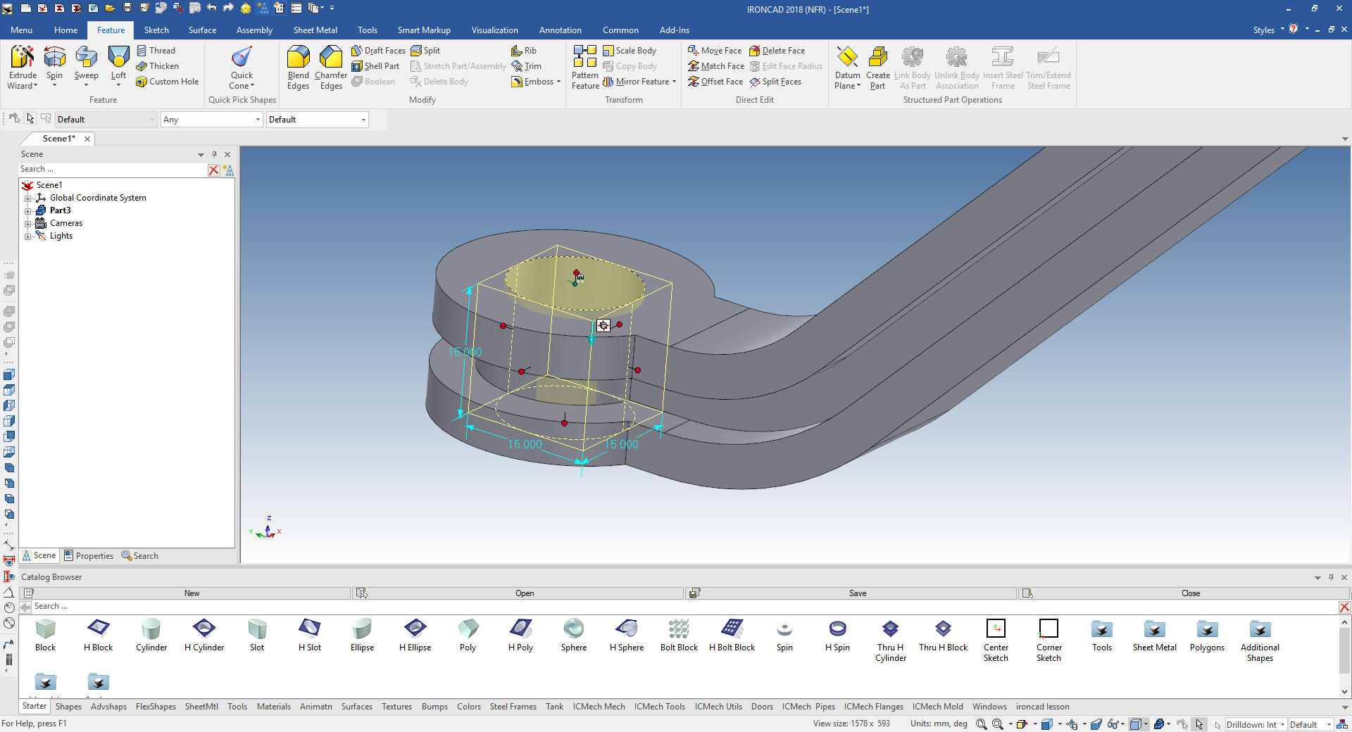
Dragging and dropping a hole cylinder to the center of the top
cylinder we create the 15mm hole.
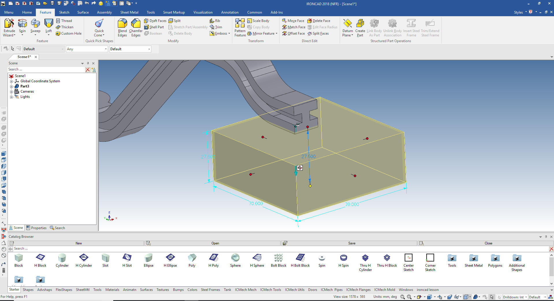
We are done with the handle. We drag and drop a block to the bottom
of the right side of the handle and size it. Why the bottom? You
will see in a couple of steps.
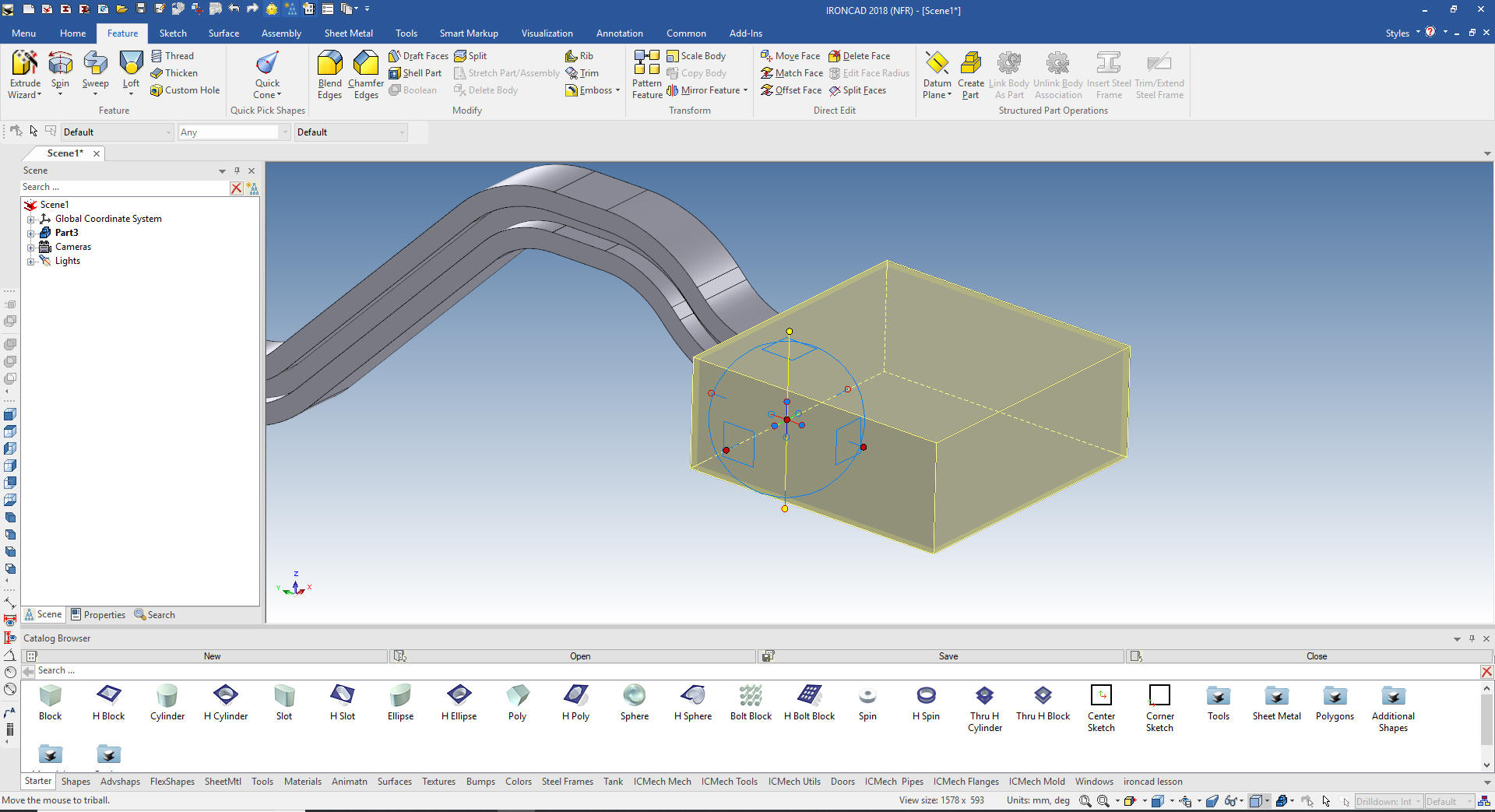
We move the block in the correct location with the Triball.
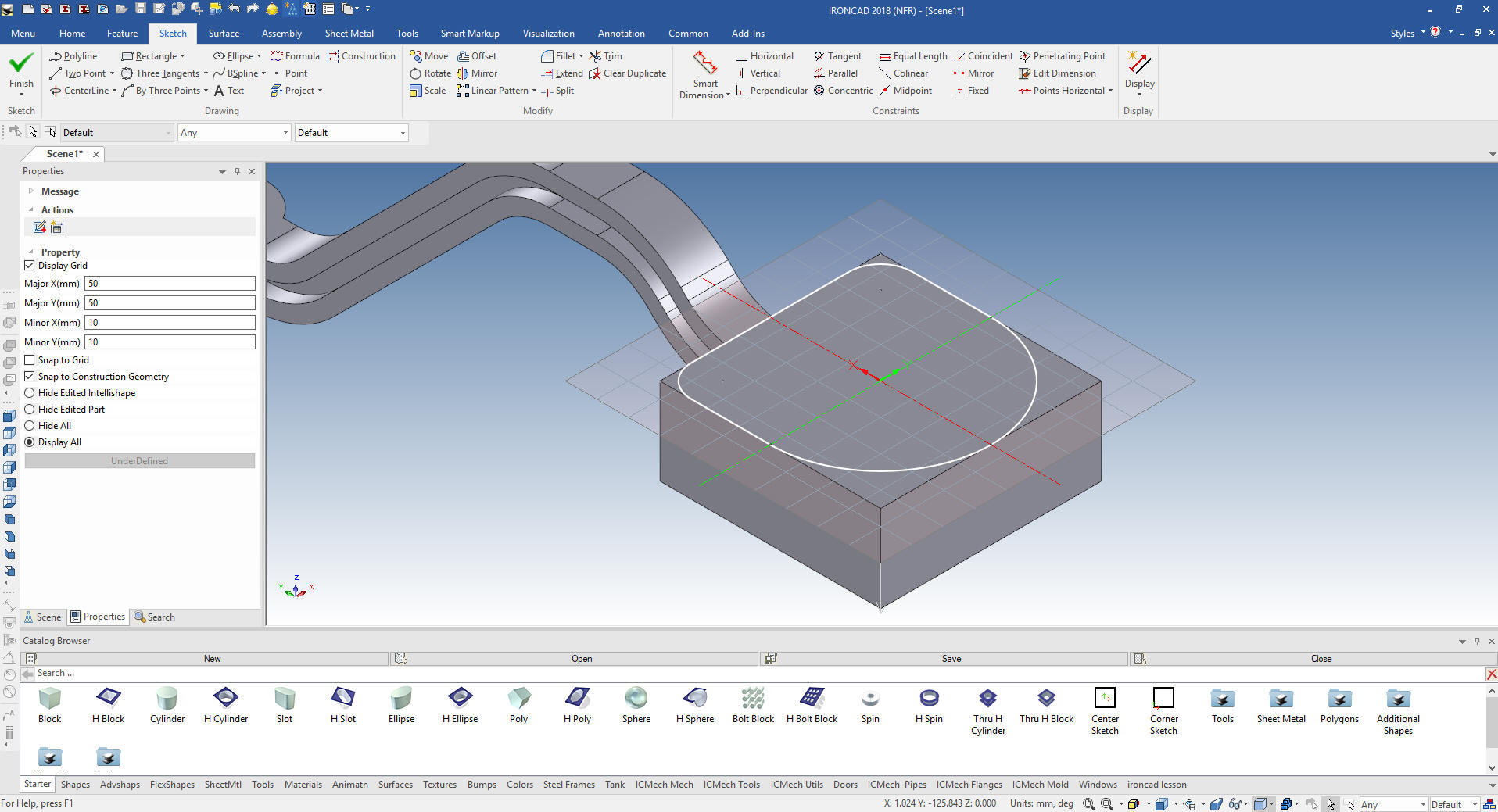
We are going to do a process that is only available in IronCAD. Each
intellishape, in this case a block is based on a sketch. I will edit
the sketch to the dimensions of the cup. I
We select okay and we have the basics for the cup.
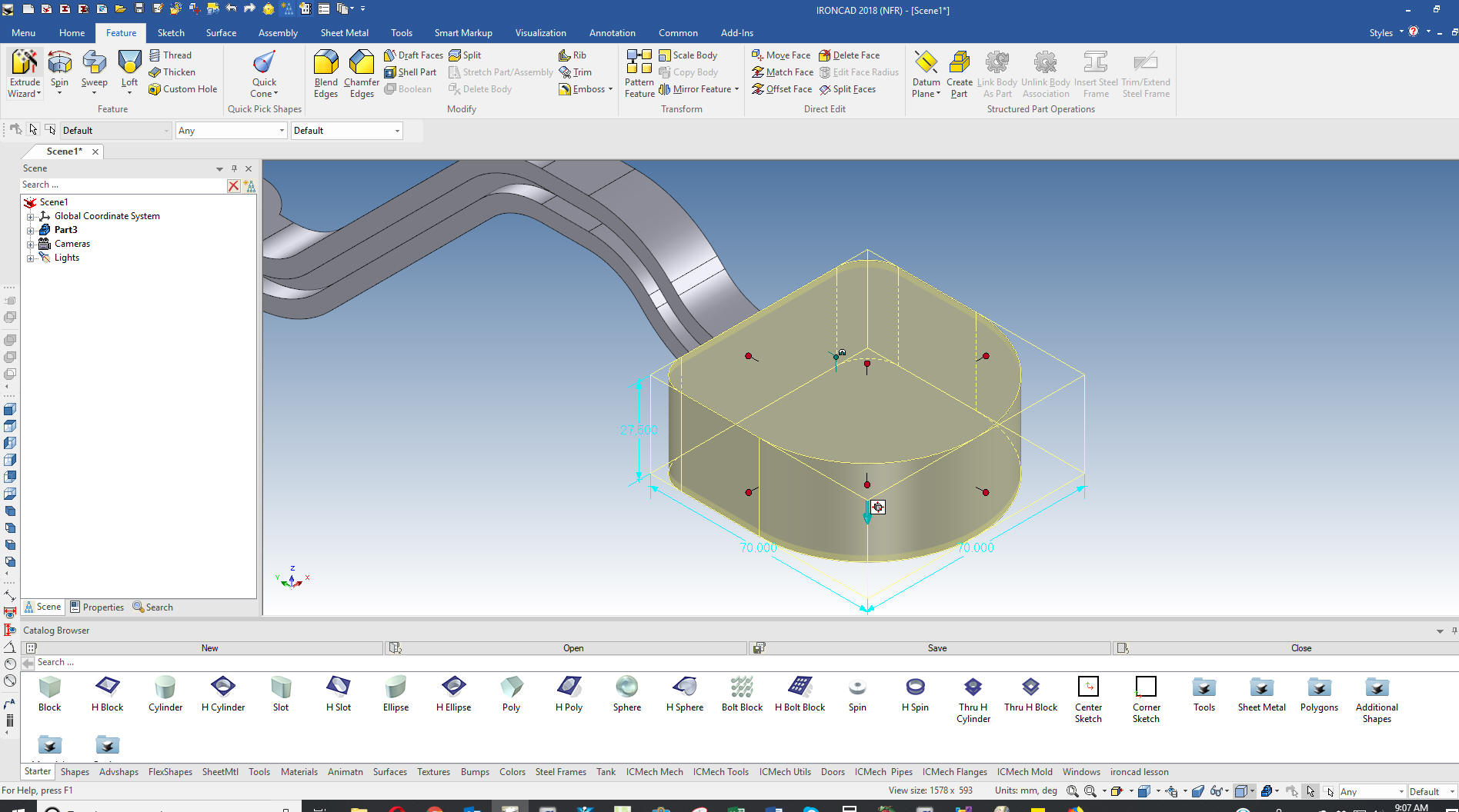
Remember when I dropped the block on the bottom of the face of
the handle? That set the block with the correct extrusion direction
for the next command. I usually don't add fillets in the sketch. But
as you can see in the drawing the fillets are tapered with the draft.
The Solidworks presenter missed this.
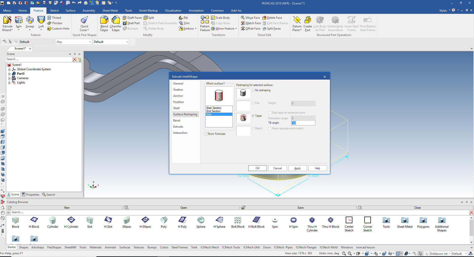
We go to the intellishape level and select surface reshaping
select size and taper at -10 degrees. This is an incredible
function only available in IronCAD. It just adds an level of
flexibility unknown to the Solidworks clone or direct edit only
systems.
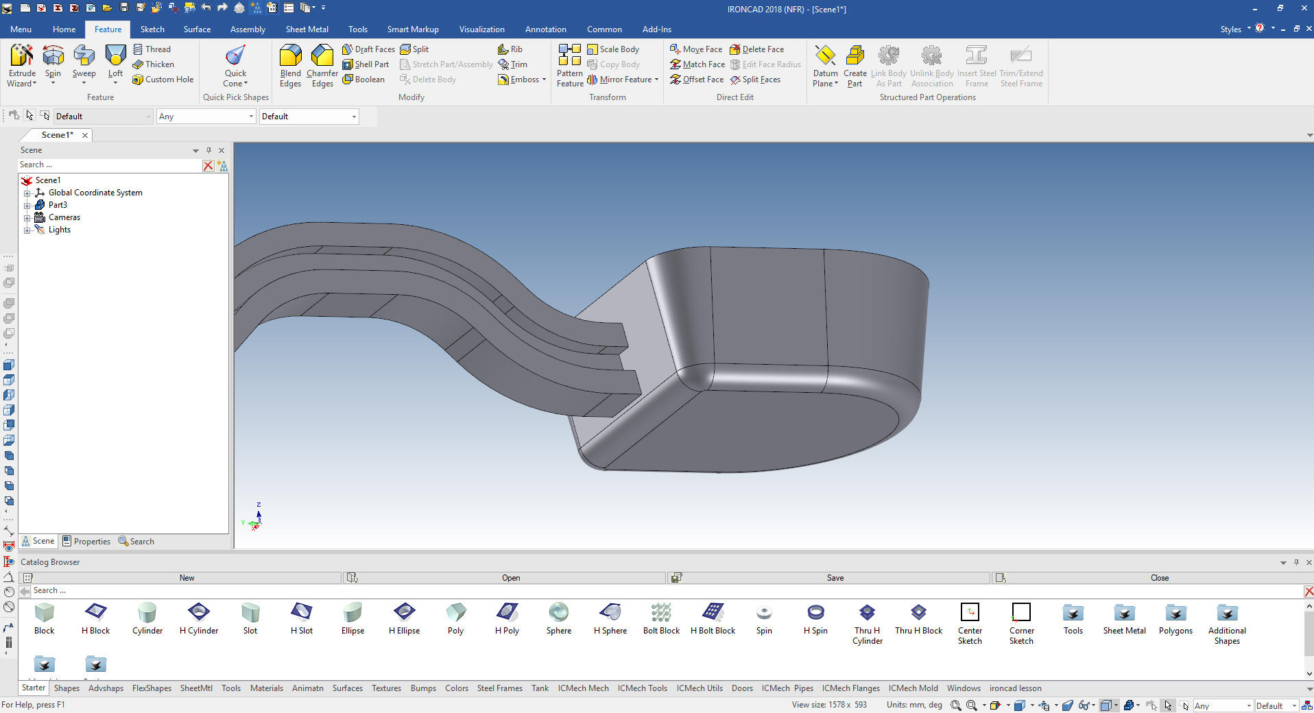
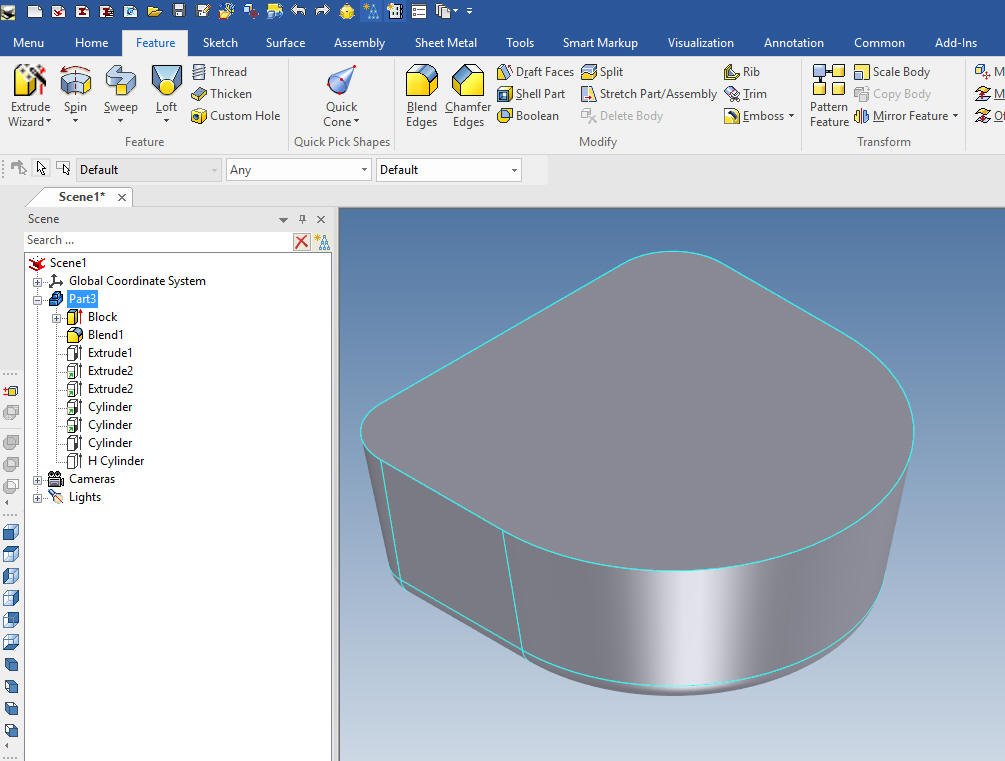
We add the 5mm fillet at the bottom of the cup and we have the
correct shape.
As I said in the beginning I would have started with the cup due to
the shelling process. But we can easily do it in any step. We first
suppress all of the steps in the history and move the block and
fillet that makes up the cup to the top. We can also set the
autohide for the catalog browser since we are done using it.
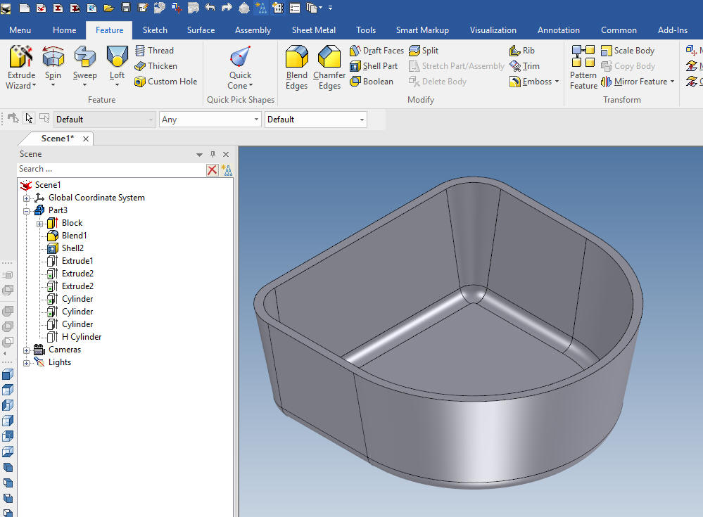
We
will now shell the cup and move the shell just under the blend.
We unsuppress the rest of the history and we can see that the handle
now sticks into the cup.
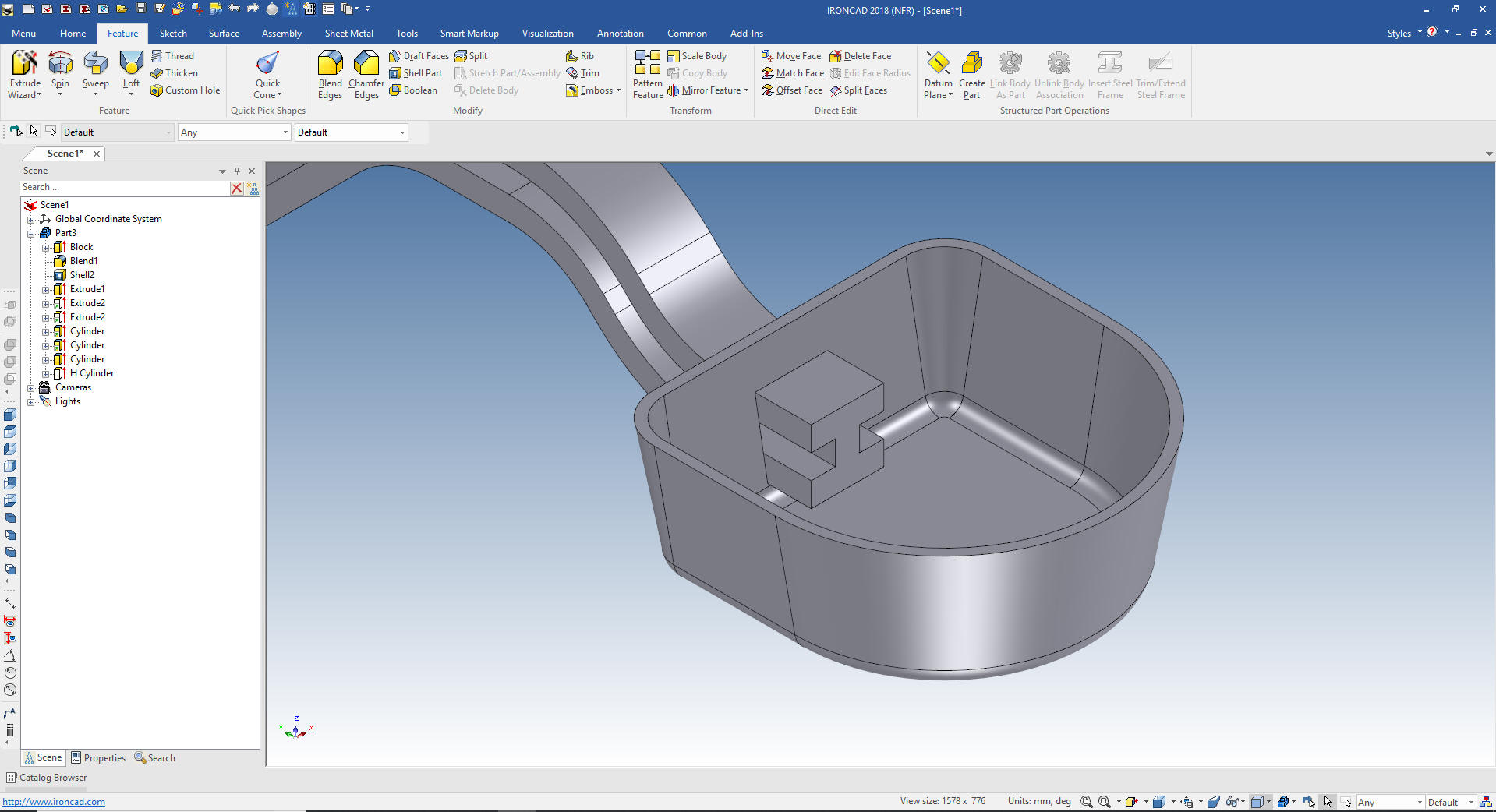
If we
would have use the swept command we would have to jump through a
couple of hoops as the Solidworks user did. The sweep command should
be only used if an extrude command cannot be used. The Solidworks user
could have easily designed the handle this way.
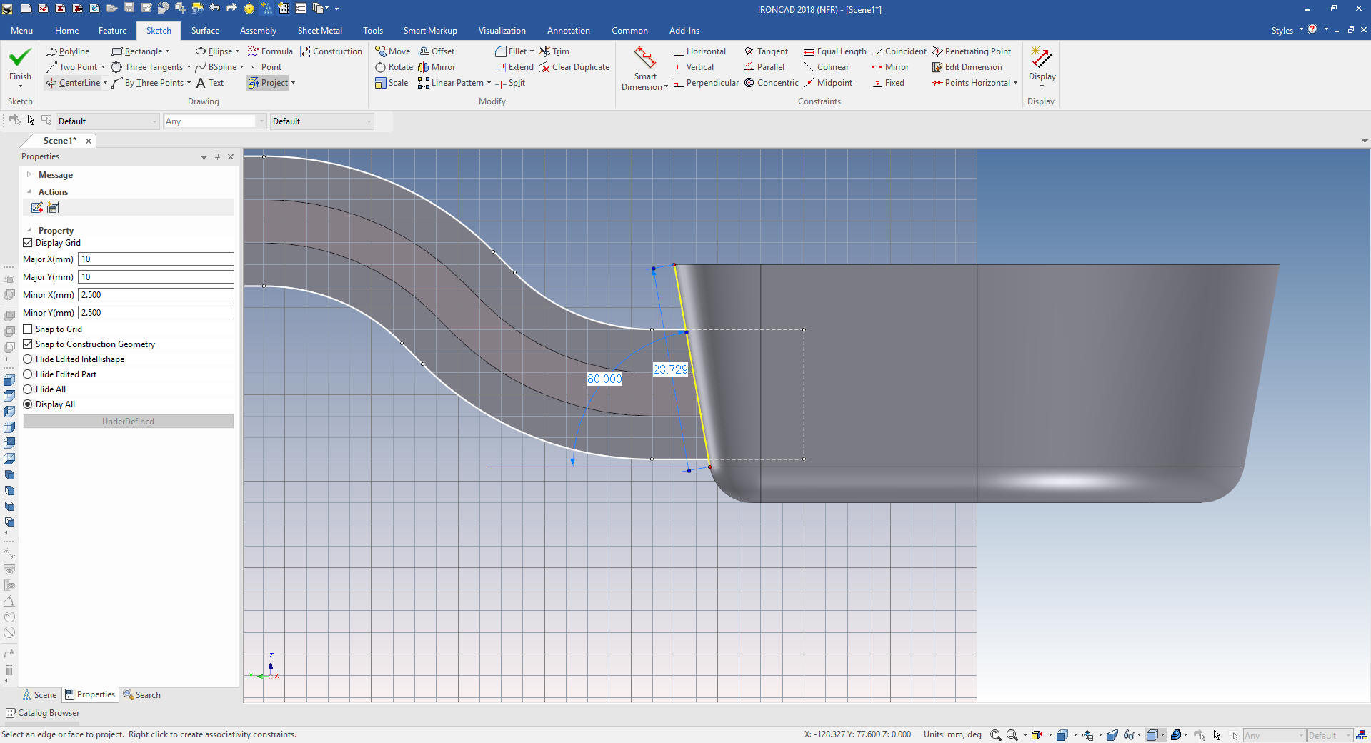
All we have
to do is edit the two sketches by projecting the cup face and
trimming the entities.
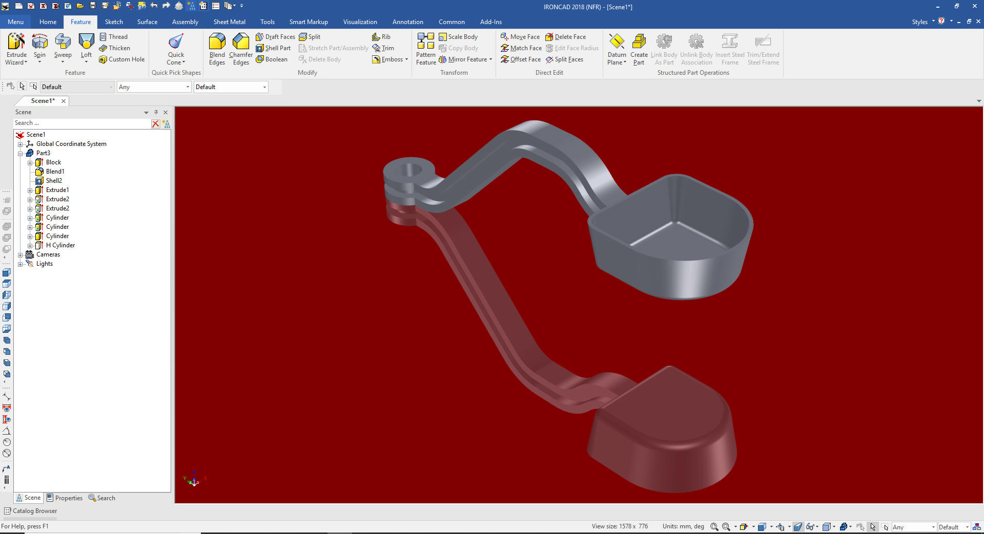
The
dipper is done! Wasn't that much more fun? Working directly with
shapes is much more productive and pleasurable.
This is
another stark examples
of how Streamlined Sketching and Feature Based Modeling utilizing IronCAD's drag and drop of smart editable
intellishapes from a catalog and
the use of the Triball can increase productivity easily 5X. I
usually estimate 5X increased productivity in conceptual design and
10X in changes, and I believe I am being conservative. IronCAD can
edit most of the Solidworks clone parts and assemblies faster than it
can be done in the native CAD system.
Give me a call if you have any
questions. I can set up a skype or go to meeting to show this part
or answer any of your questions on the operation of IronCAD. It
truly is the very best conceptual 3D CAD system.
If you are interested in adding professional
hybrid modeling capabilities or looking for a new solution to
increase your productivity, take some time to download a fully
functional 30 day evaluation and play with these packages. Feel free
to give me a call if you have any questions or would like an on-line
presentation.