|
Reusing Existing 3D CAD Models
for a New Product Line PHASE I  |
|
Phase I Reusing existing CAD models for a new product is a very cost effective way
of cutting the design costs. But many CAD systems just don’t offer the tools
to do this effectively. The best way to show a new technique is to show a
real life project so I thought I would document the process. My customer sent me a sketch of a basic version of one of their products with a few dims and notes. This one said make it 3.5 x 8 x 17. We will need 6 receptacle on separate mounting plates for the four different countries.
The modular design was something I presented them on an earlier design and
now they want to include the concept through their complete Product line. Now this presentation is a bit long, but hopefully will be worth the time. The project took me 6 hours. I did a mixture of conceptual and detailed
design. Just enough to show the client and get their input. I
am using IronCAD for this project. I have been designing this type of product
for the last 5 years so I have done this many times before. As I work I
think of those that cannot work to this level of flexibility and I thought
it would be interesting to a few to see this how this type of CAD design is
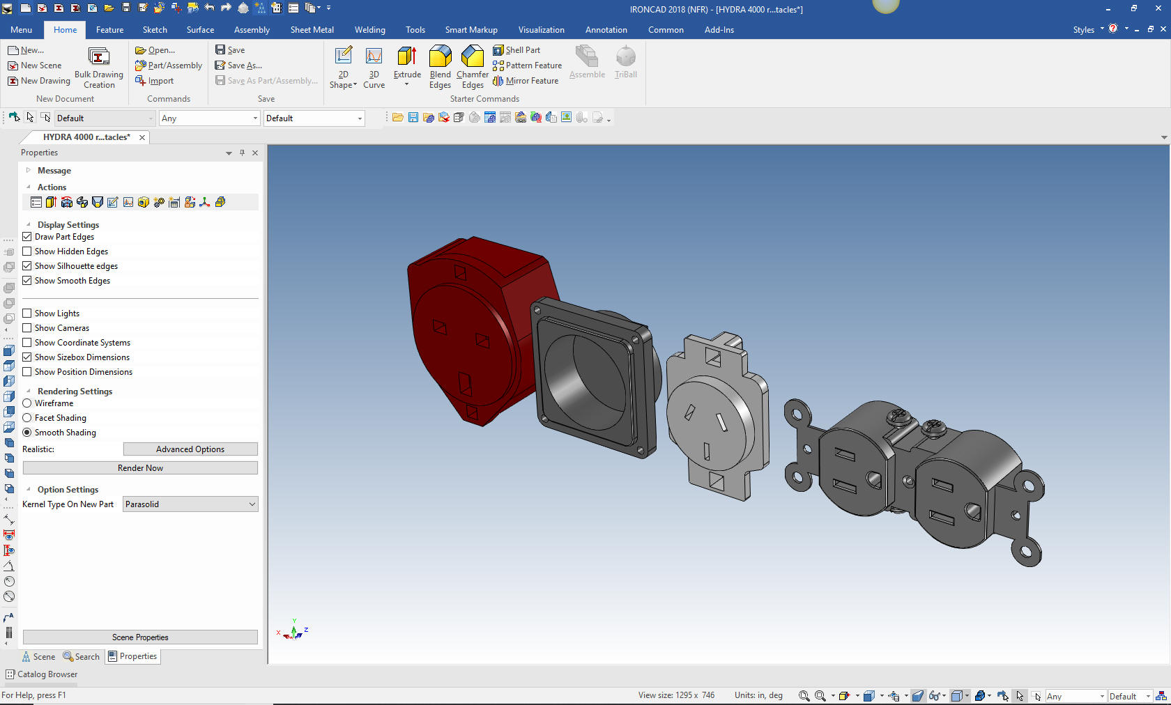
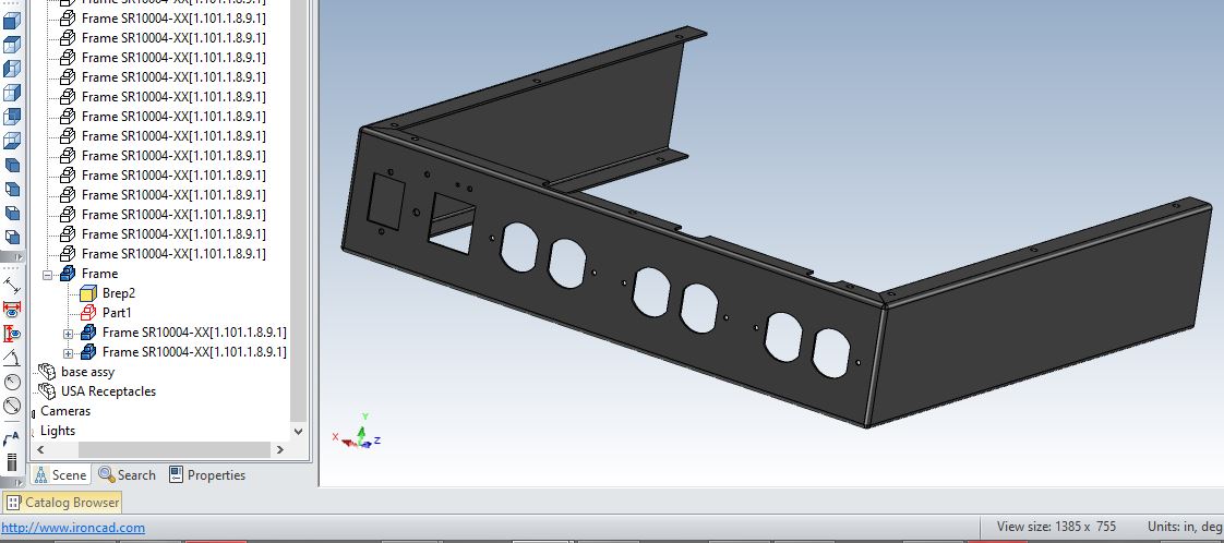
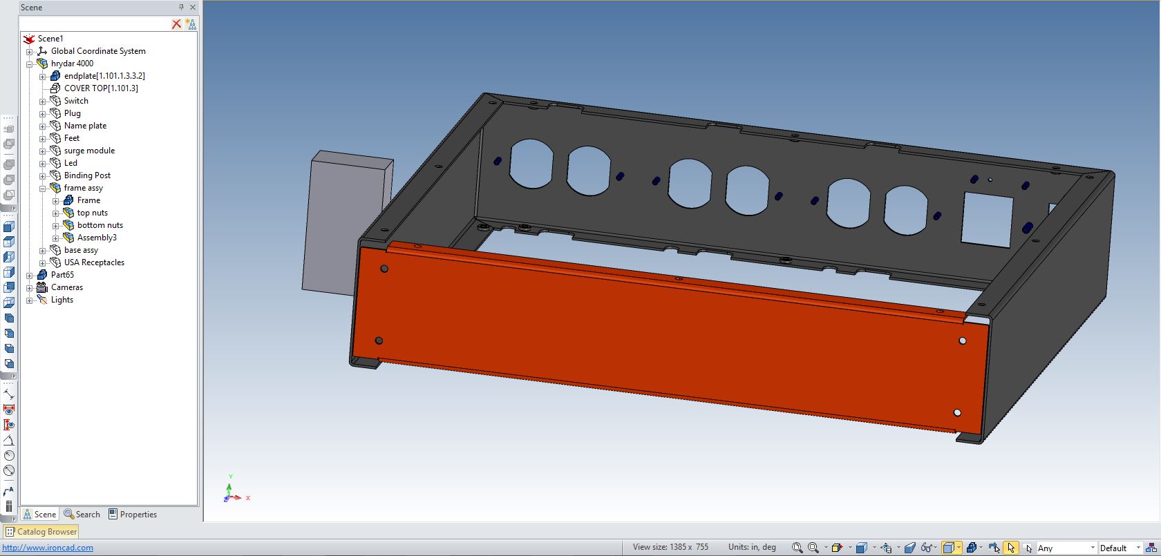
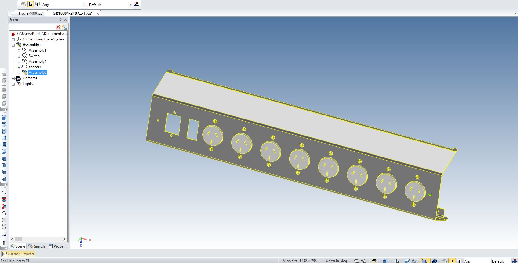
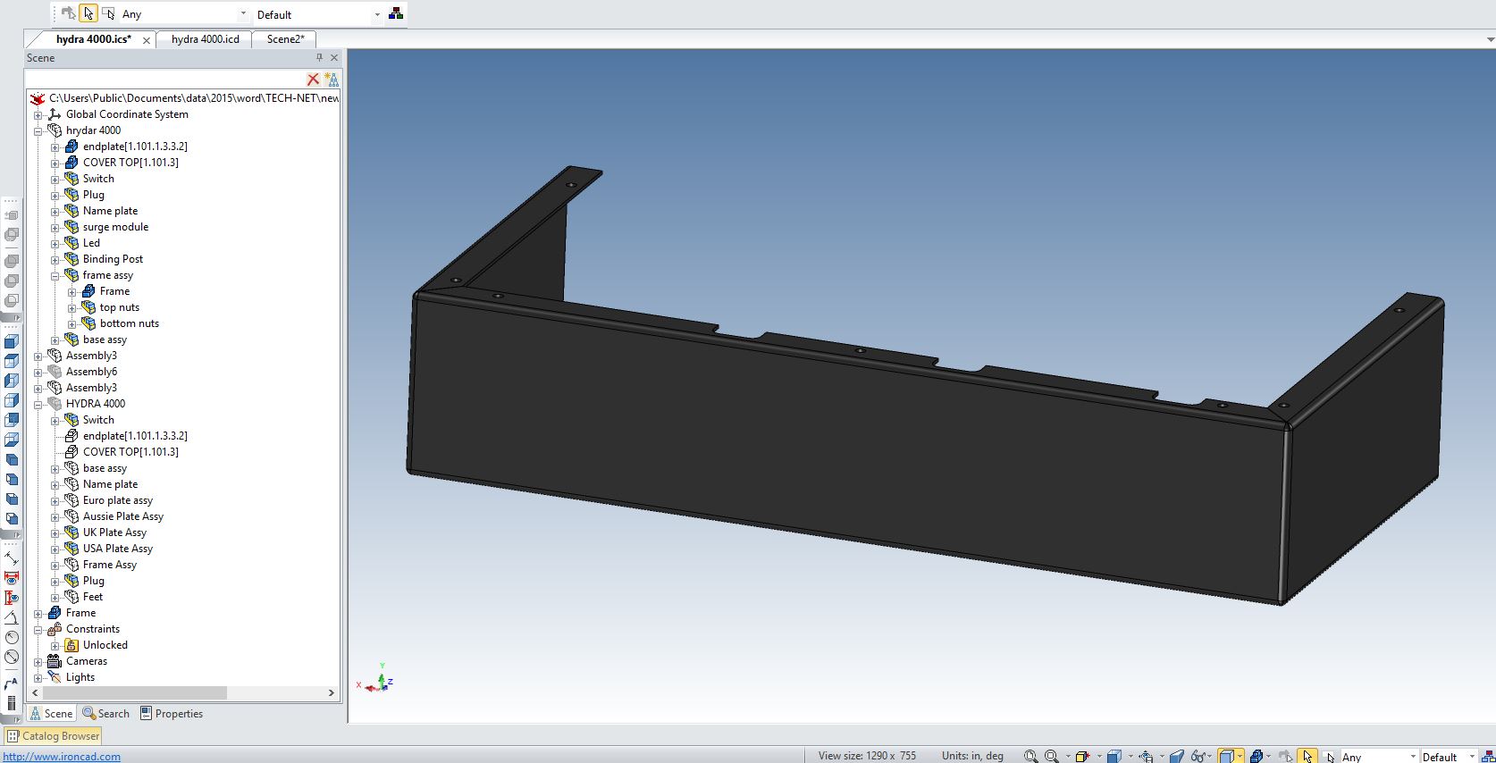
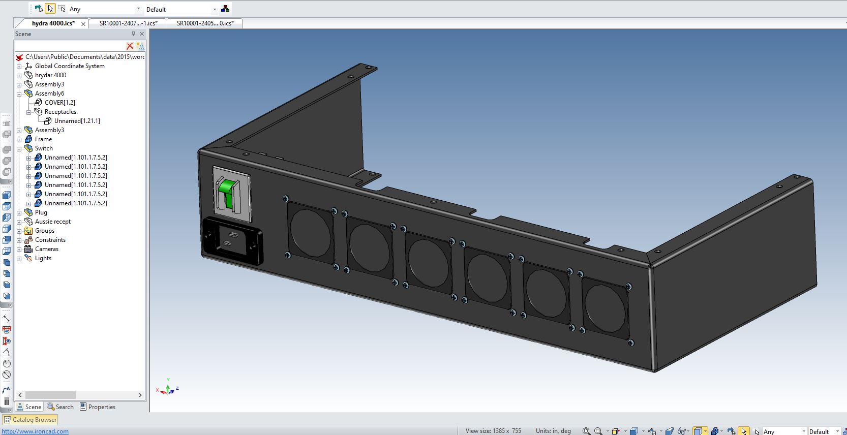
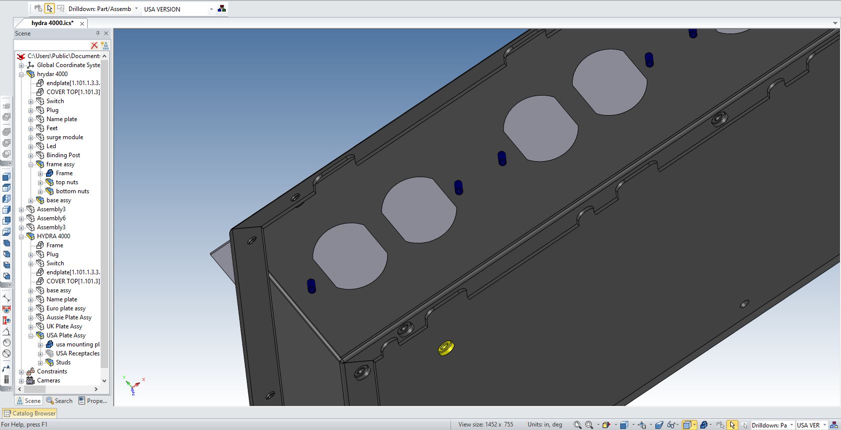
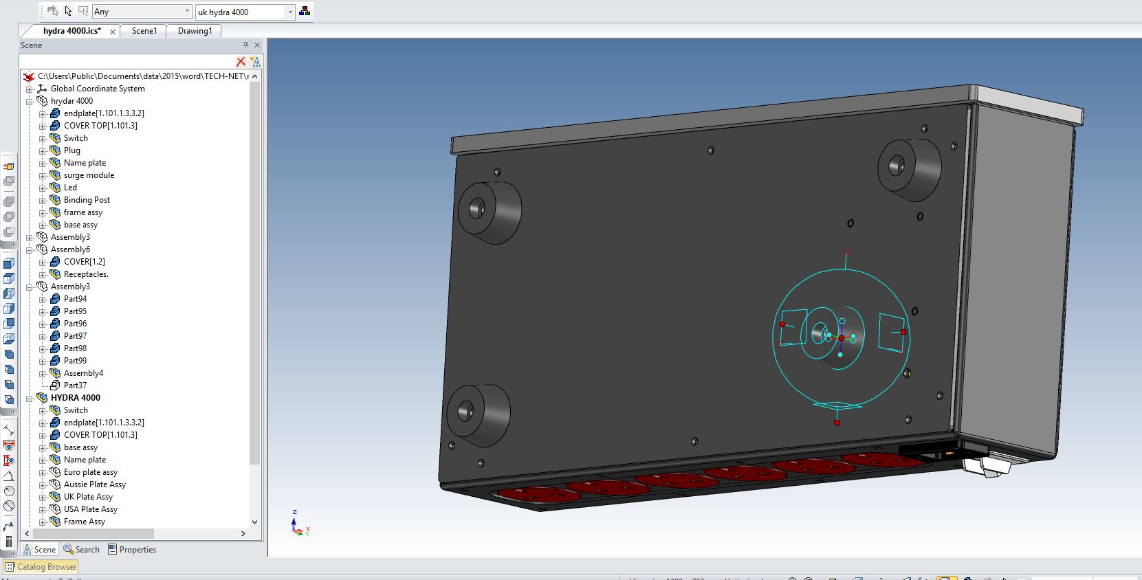
applied. Here is the original sheet metal enclosure I imported this as a parasolid from a different program. I use a couple of different 3D CAD compatible systems. Notice in the scene browser (history tree) that all of the parts have come into one scene and individually noted in the scene browser. We call this the Single Model Environment. The history is included in the individual parts. You can have external referenced parts and you can decide at any time in the design process. Since I work alone this is not a problem. The single model environment is the productive 3D CAD feature. Note: It is called a scene in IronCAD because it was originally released as a graphic design package called Trispectives. With this heritage if offers many more design options than the conventional SW clone.
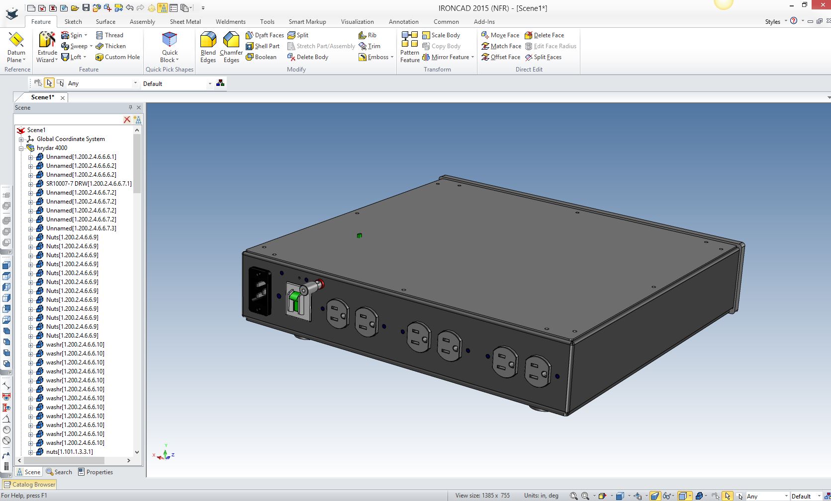
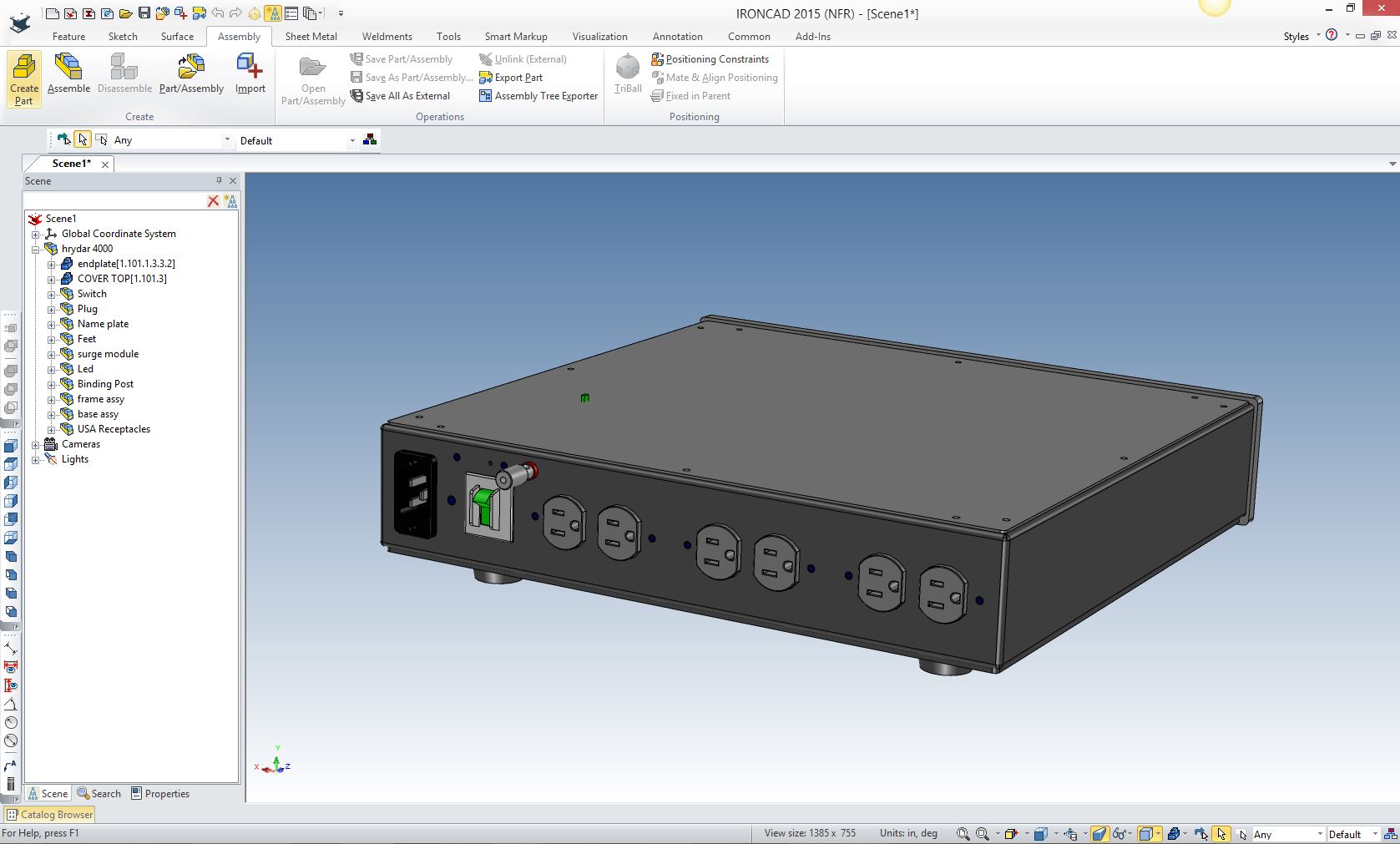
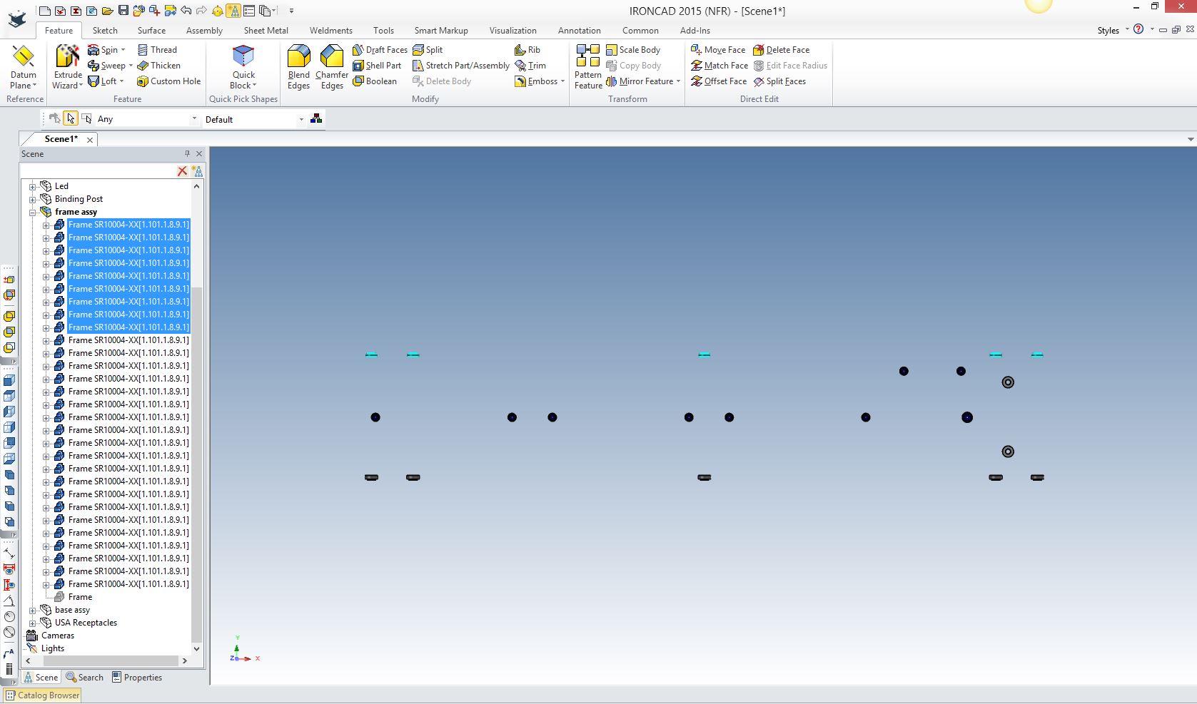
It needs a bit of clean up to put the parts into separate assemblies for ease of manipulation. You can do this by windowing on the screen or selecting from the scene browser. Now take a look at the scene browser. We have reduced it to the basic parts and sub-assemblies. This is just one benefit of using a single model environment.
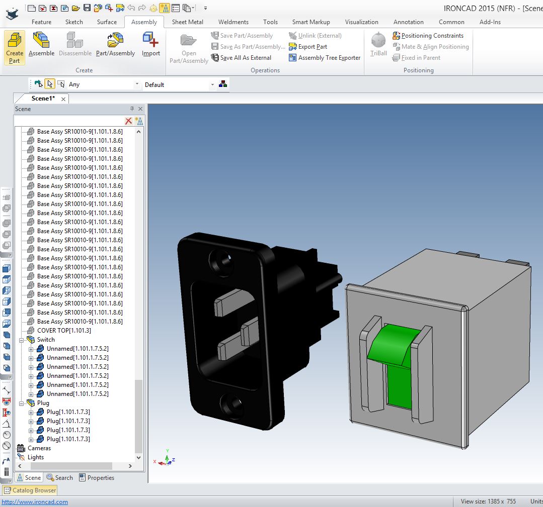
You can see here how it was done with the switch and plug.
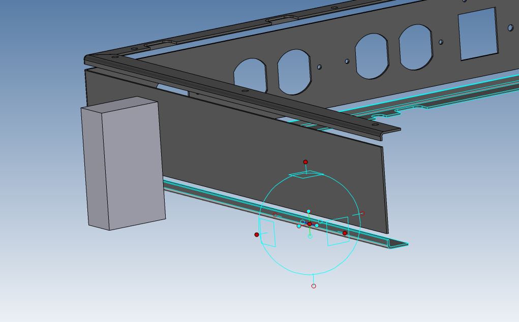
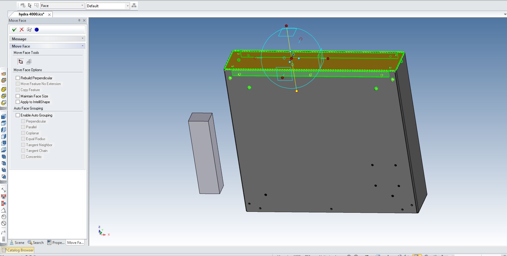
The existing frame was 17 x 3.125 x 15.75. We had to increase the height to 3.5. I tried to move all of the associated faces which would have been one step. But once in awhile this function fails. So resorted to the split function. For some reason I thought it would be easier to keep the receptacle centered. Just one of those things where you have your mind set. I soon realized it didn't really matter but it was just a small extra step. The block is there to set the locations. It is a bit of a strange way to do something, but I really hate putting in numbers. I dragged and dropped a block and match it to the existing faces of frame. Then just grab the handles and put in the 3.5. Then place the triball on the face and then match the point or face on the block. (The Triball has added a new from/to feature that eliminates creating the reference block) Note: This step has now become much easier, they added "Edit Distance from Point/Center Point
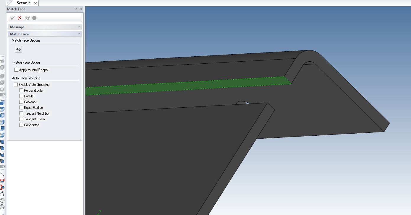
Then I just extended the faces with the match face command.
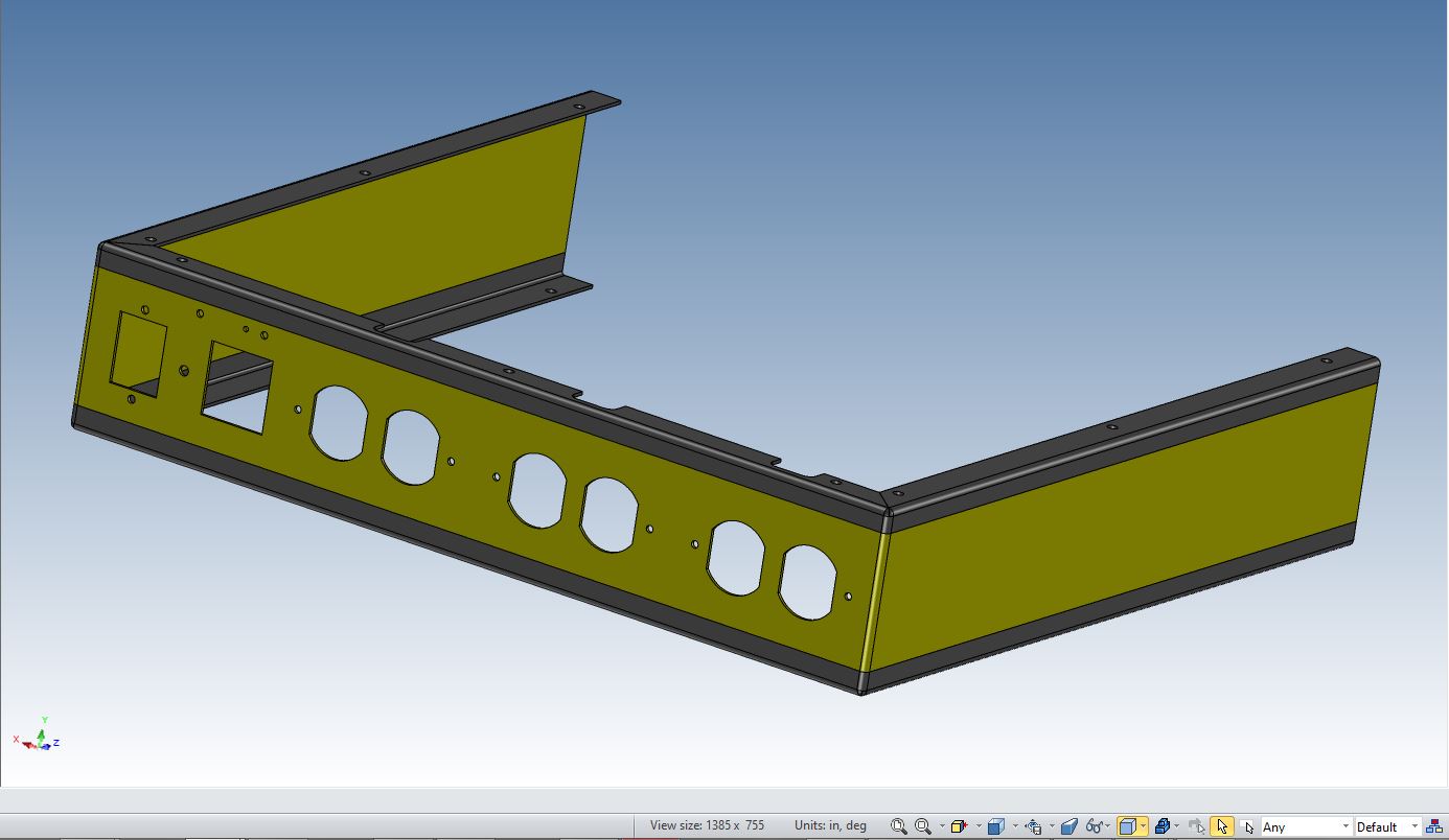
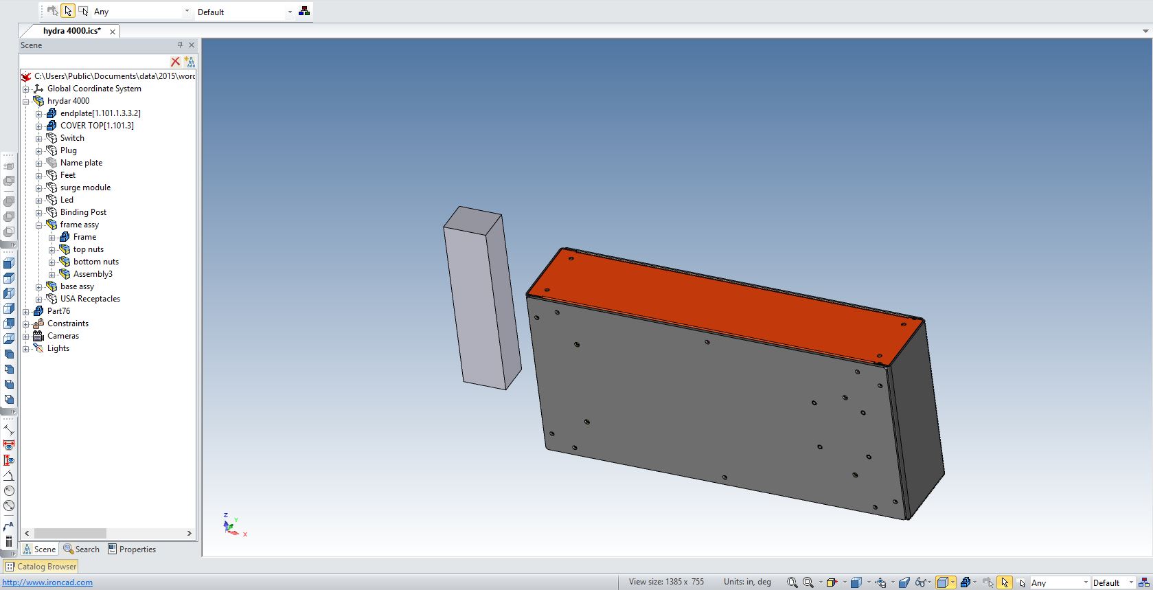
Here is the results. I changed the color to clearly show what we are doing.
Now to Boolean join them.
Step completed. Notice what the new frame is made up, the original brep2 the cutting part and the two moved split pieces. IronCAD has an option of combining all of the features into one single Brep. This is used to eliminate any extraneous features or components.
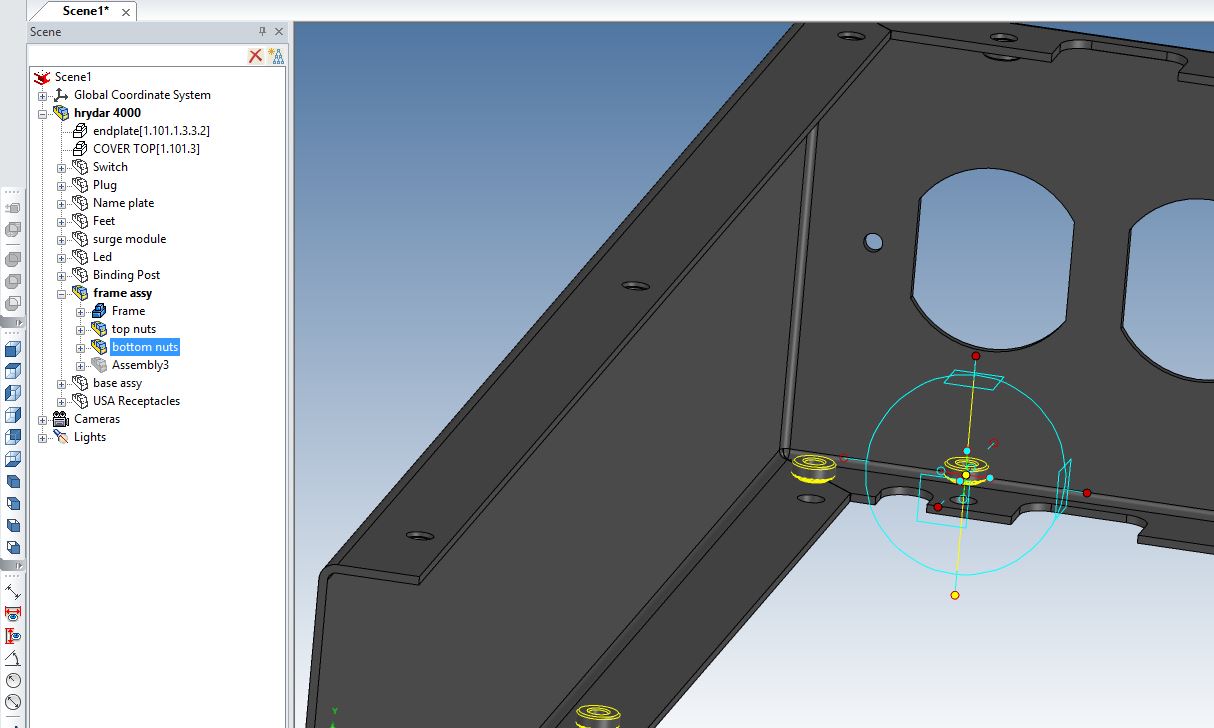
Here is another example of creating an assembly. the fasteners and the frame will be made into an assembly and sub-assembly to send off to the supplier or create a detailed document. We are relocating the nuts into place. You can see why we made an assembly out of them. They are much easier to manipulate.
Here is the first step of the frame change completed.
Now for the end plate
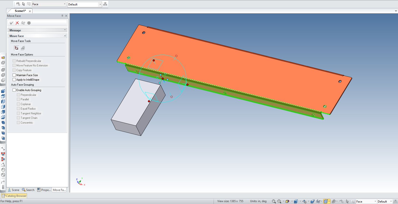
With the end plate we can use the move face function. Notice we also have selected the mounting holes the nut inserts are also included. We move the triball to the face on the end plate and then match it with a point or face on the block.
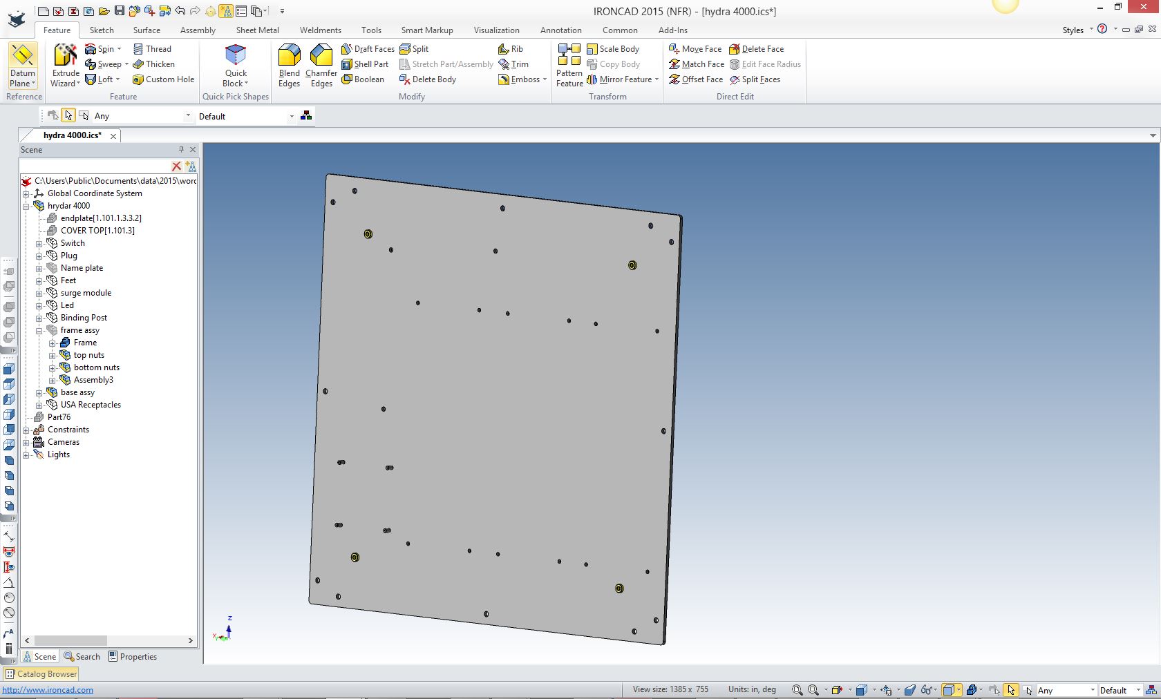
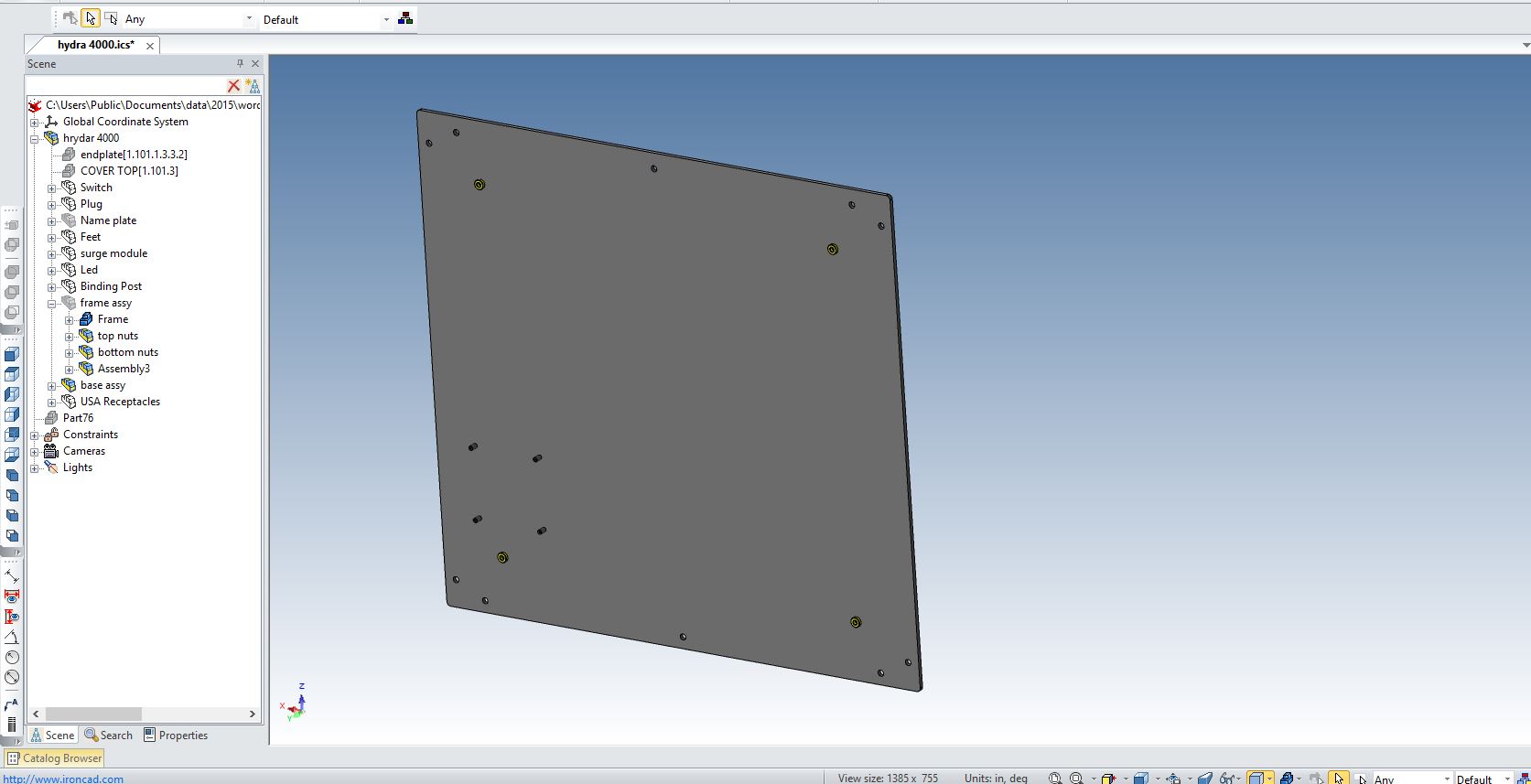
There are a few holes on the base plate that have to be removed. We use the delete face command and window the affected holes.
Here is the cleaned up base.
Again we use the move faces command to move the frame, base, cover and end plate. Notice I created another block. I know it seems strange but is nothing but a drag and drop block from the standard catalog and pull it to the 8 inches. Again I just move the triball (Move triball only mode) to the face of the end plate lock the axis in and select the center point and they select a face or point on the block.
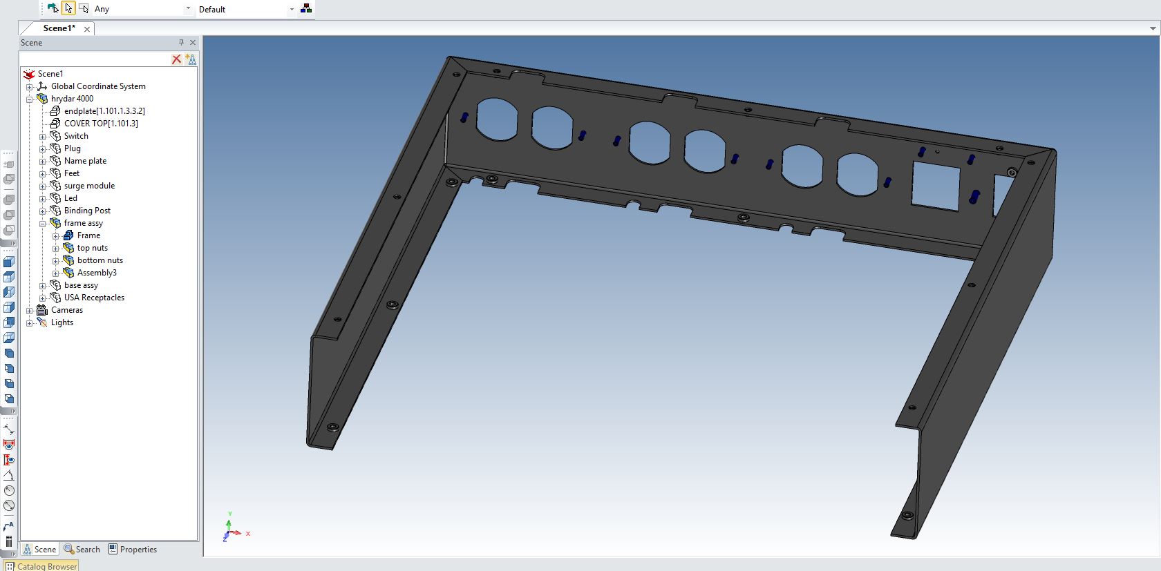
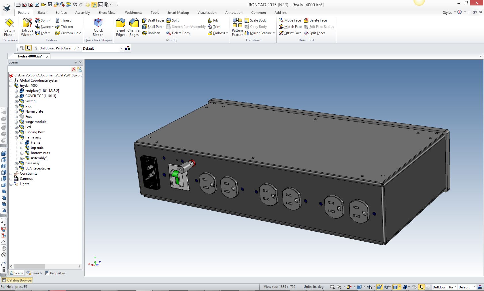
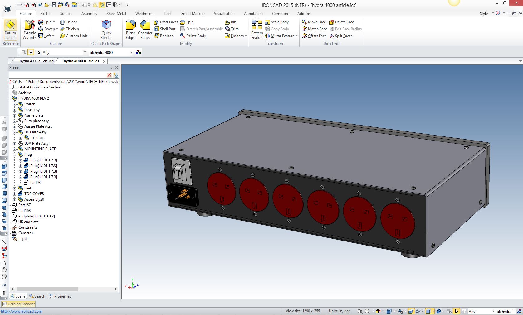
We are now basically done with the frame and end plate.
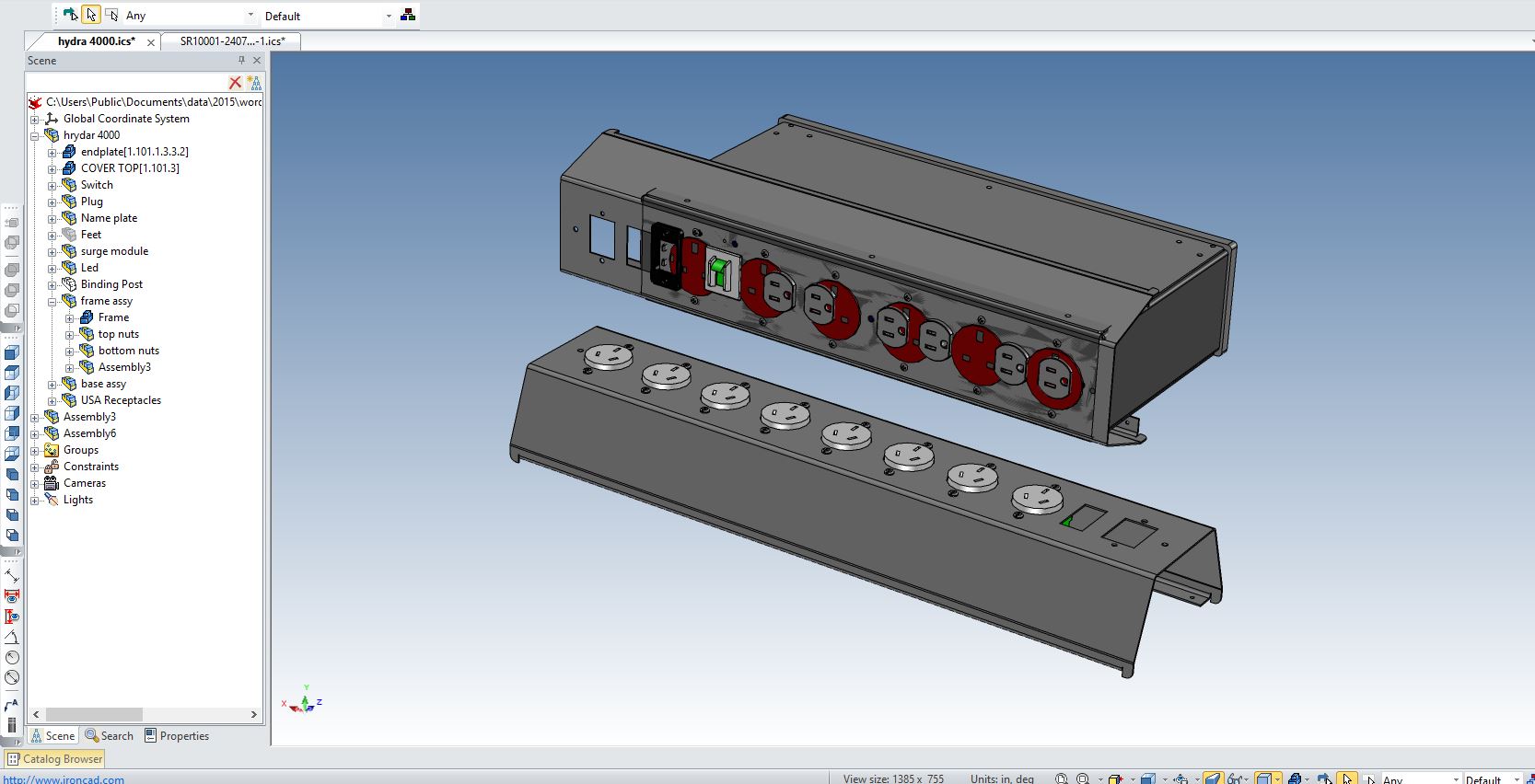
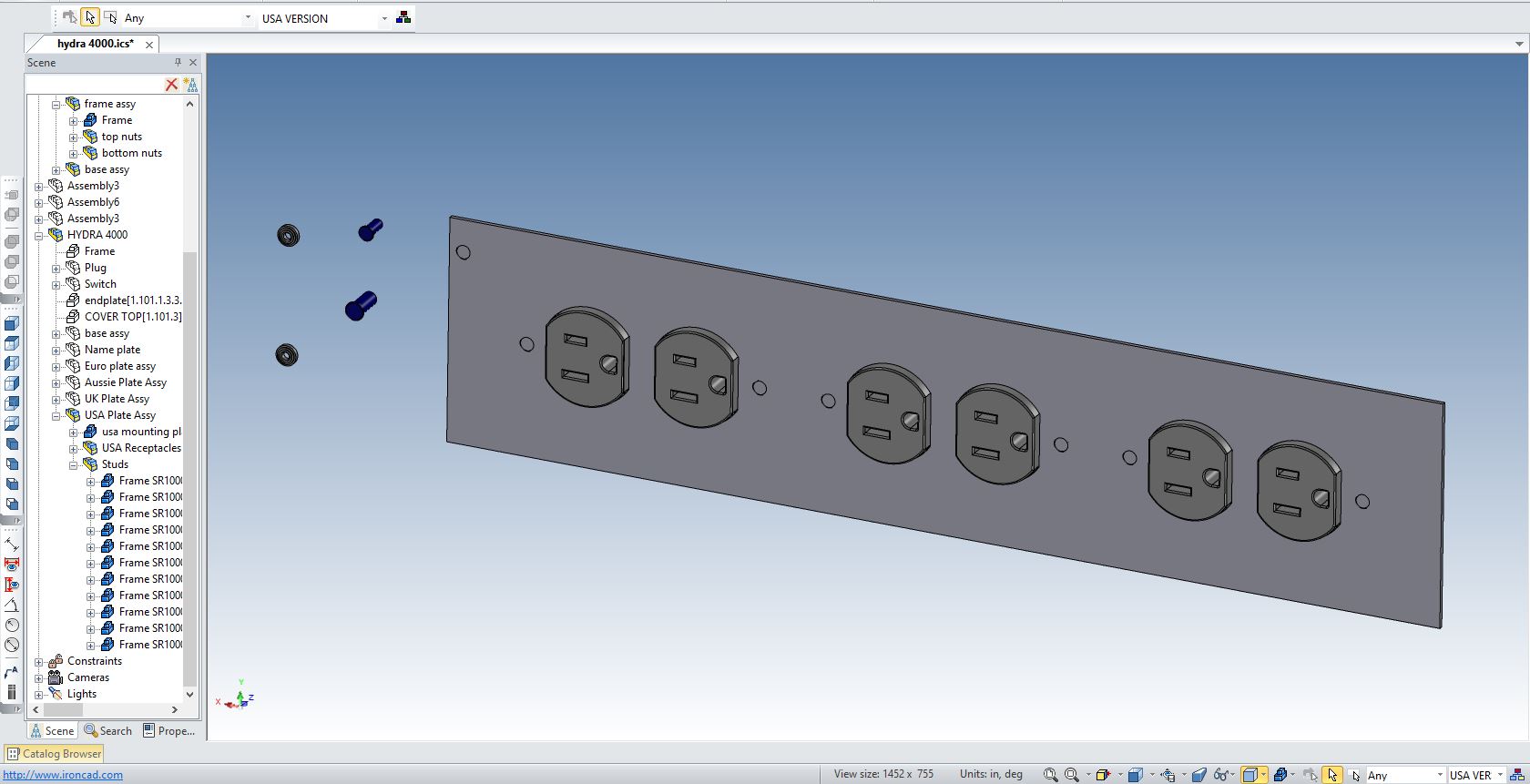
Here is the new basic configuration with the original components.
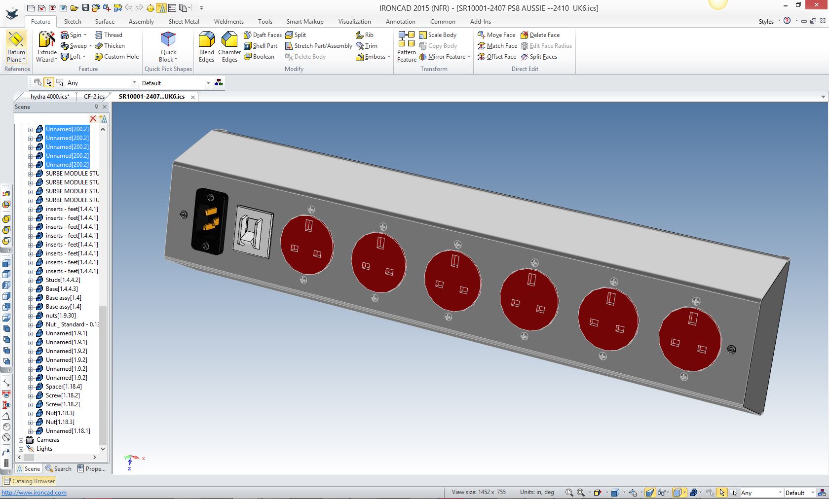
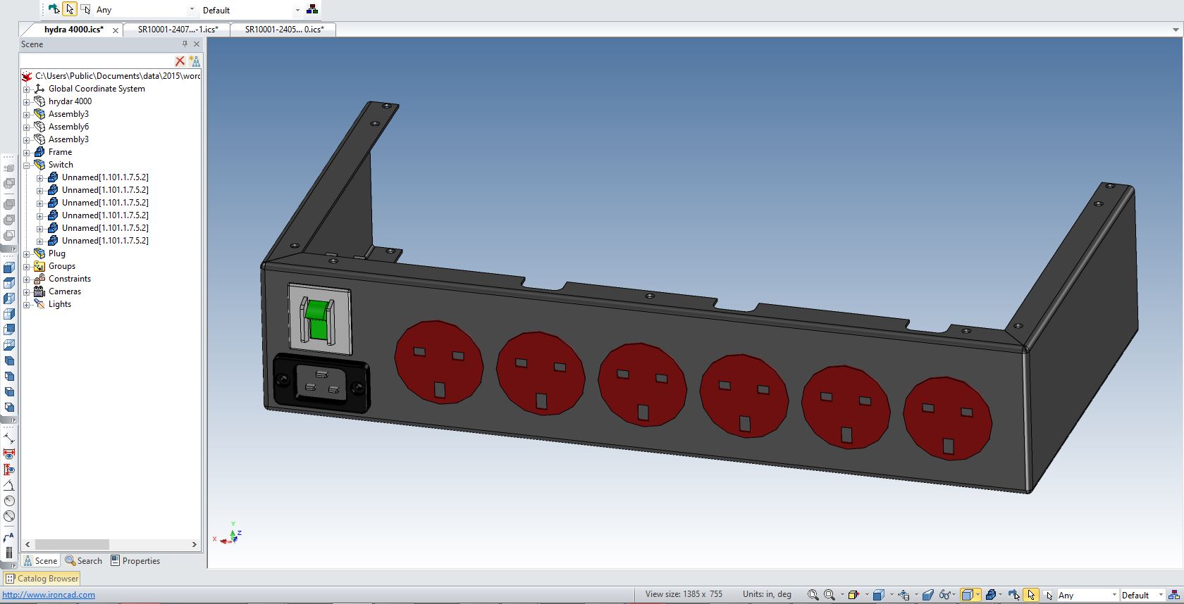
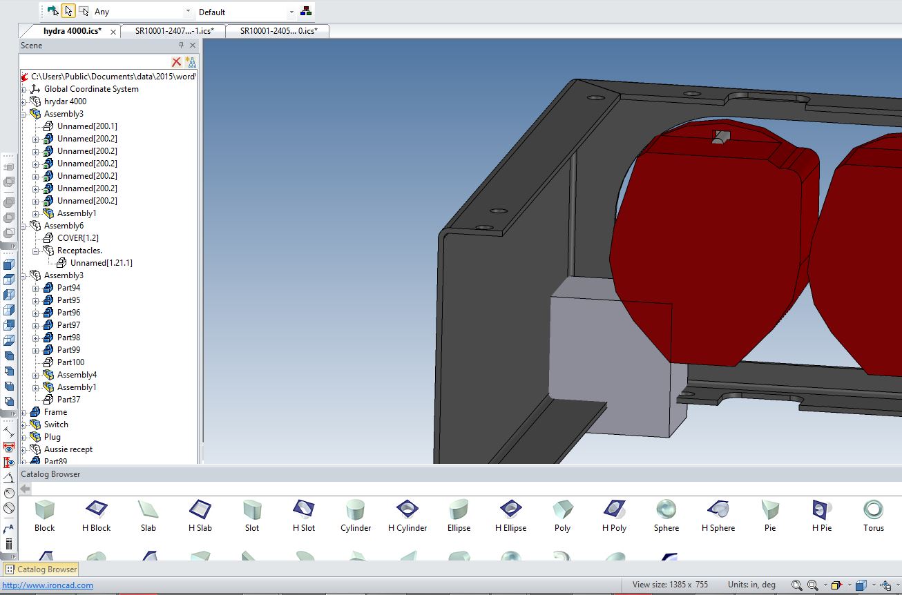
Now we have to work with the different receptacles. I have other projects with the different receptacle. I found them and will copy and paste the necessary components into the original file. Here is a UK power strip, it will be the one I will be working with first since they are the largest receptacles and will drive the basic design. I will only use the cover and receptacles.
Here are Australian receptacles. I just brought in the cover and the receptacles. Notice that they come in as another assembly.
I move the other products into the same orientation as the original assembly.
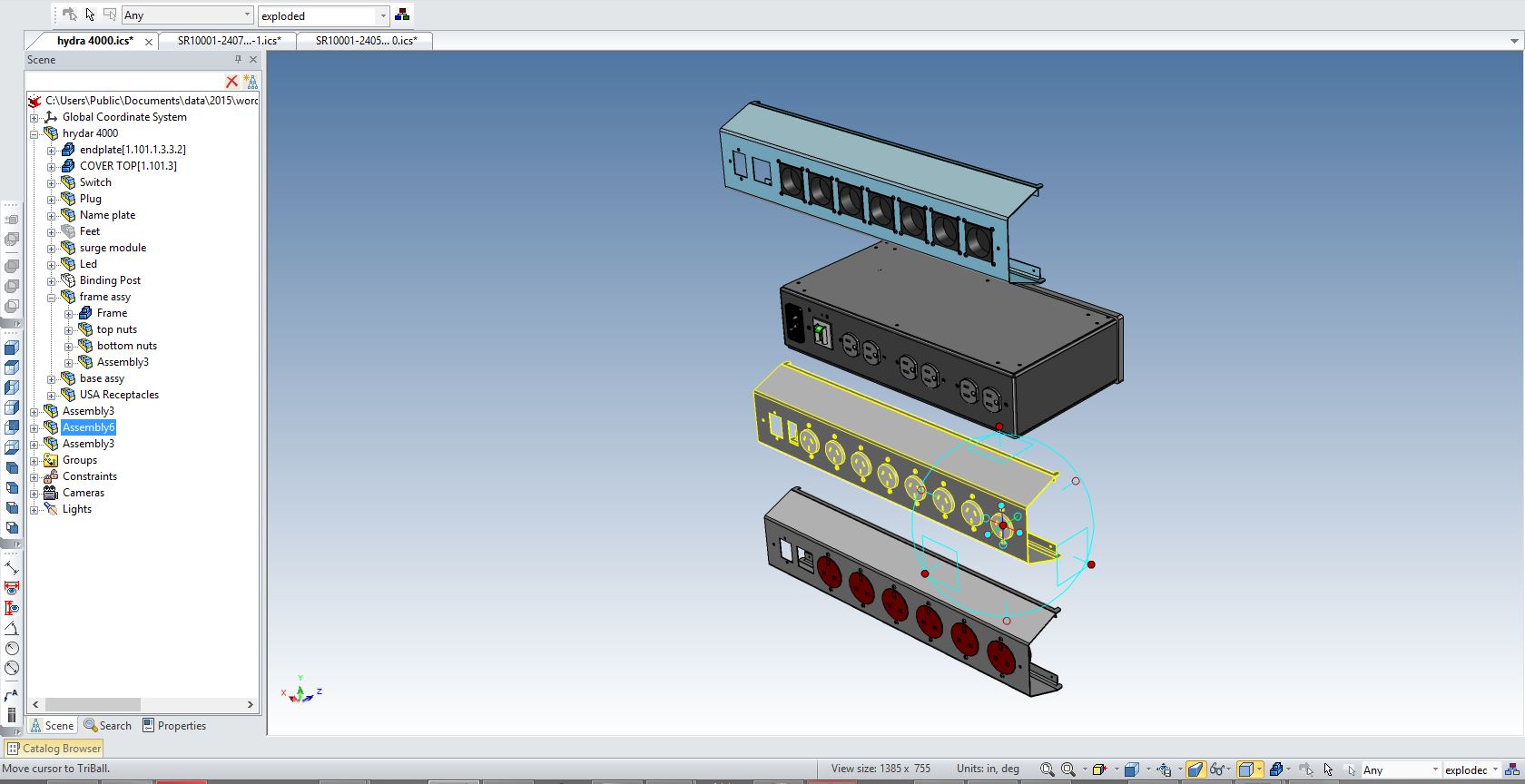
Here are all of the other products moved to show them separately. IronCAD allows you to reposition the assemblies in a special exploded configuration. This does not affect the original locations. We will use the copied assembly components for reference, we will delete the unused parts when we complete the process.
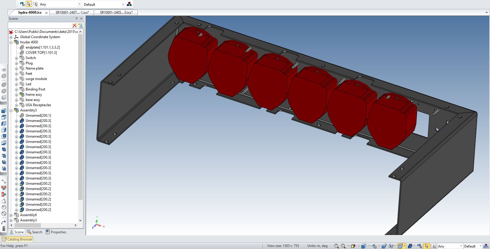
We start with relocating the UK receptacle.
Here is the frame with the holes removed. This was nothing more than a remove face command.
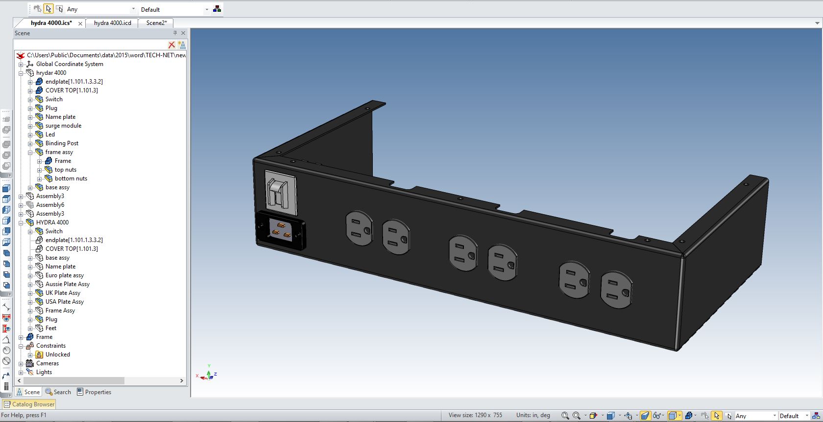
Here is the UK receptacles and the switch and plug in the final configuration.
Here is the USA receptacle evaluation
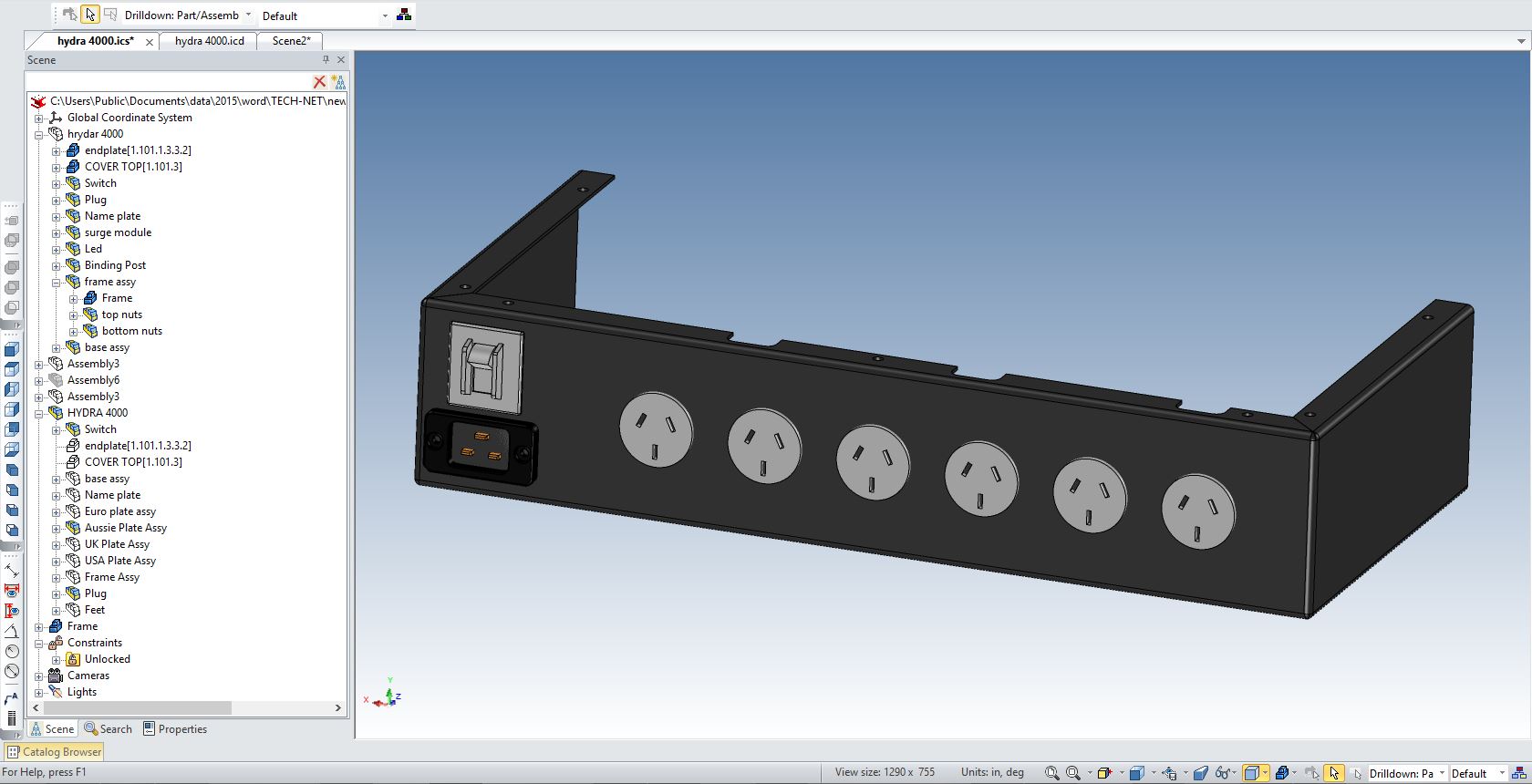
The Australian receptacle evaluation
The Euro receptacle evaluation
Now we have to create the separate mounting plate. We will start with the UK receptacle. First we drop a block as a separate part on the inner face of the frame and pull it into the correct shape.
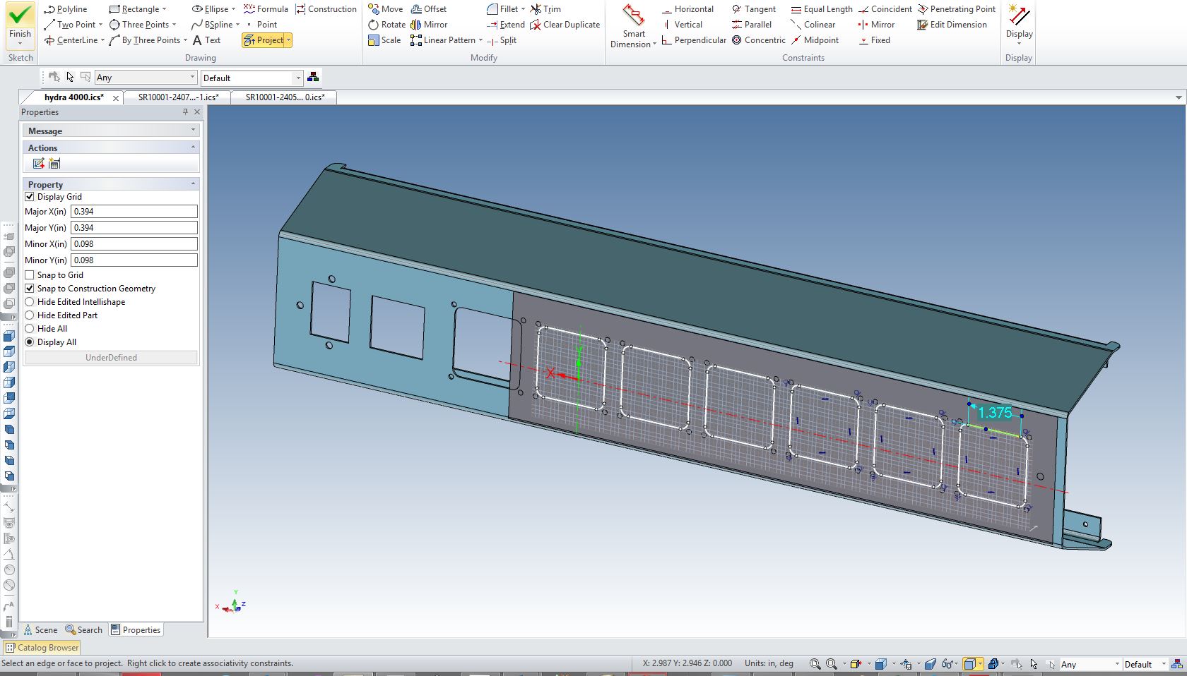
We now have the basic mounting plate. We need to cut the 6 holes in the mounting plate for the different receptacles. Here is the Euro. We create the receptacle holes by creating a sketch projecting the edges and extrude them.
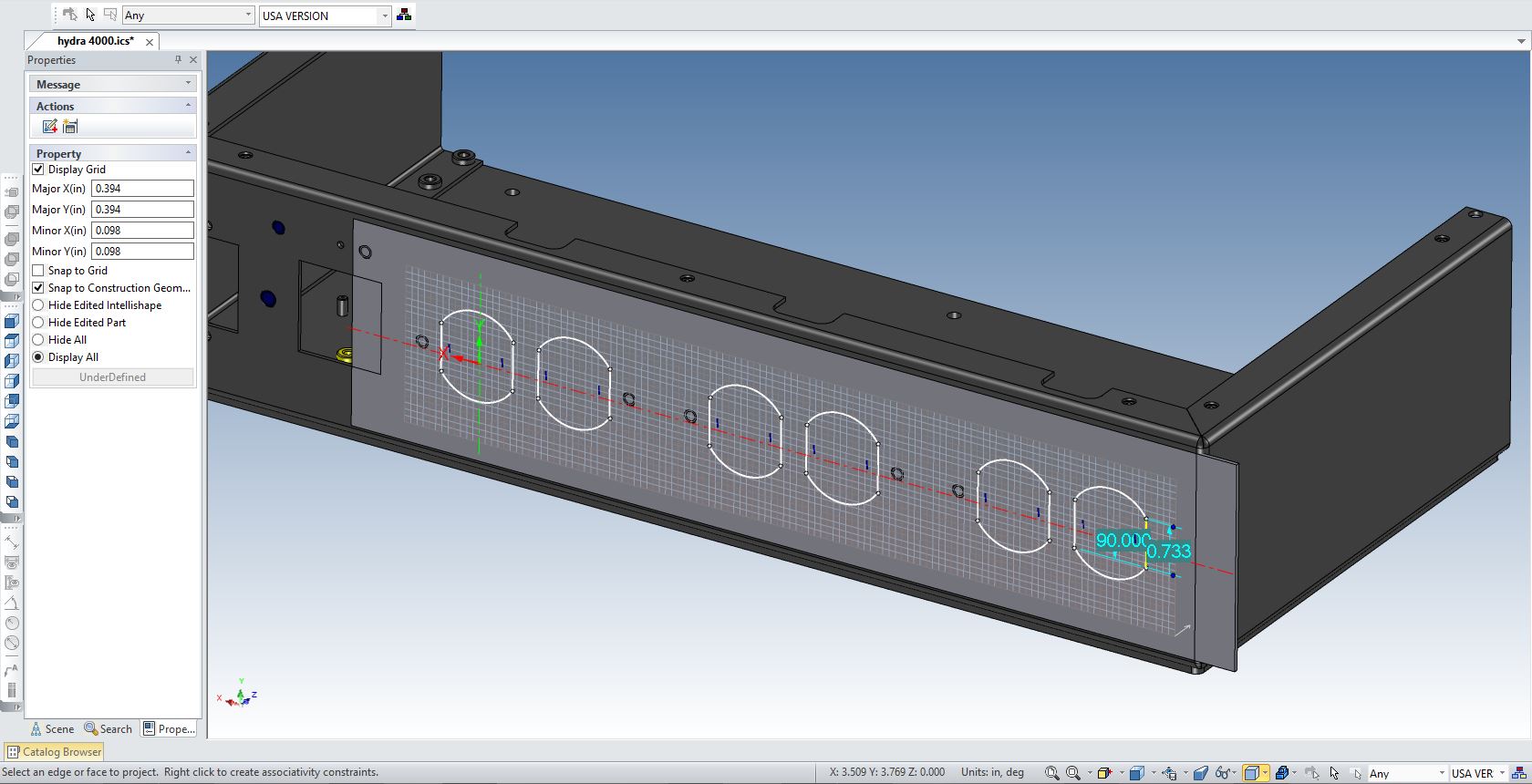
The USA
On the USA we need to add the mounting studs. Utilizing the original frame we just move them to the mounting plate assembly.
We now have the USA mounting plate assembly basically designed. Notice we have a couple of extraneous fasteners that have not been tied to an assembly.
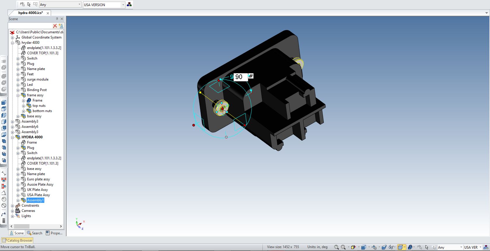
Those fasteners are for the plug and the LED. I rotated the plug and now position the nuts that will be moved to the frame assembly.
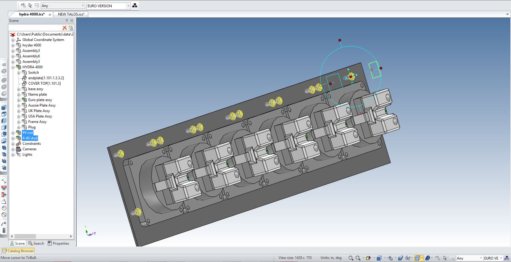
Now to the the Euro plugs. Notice that I do not have the studs and nuts included yet.
We copy and paste them from another product.
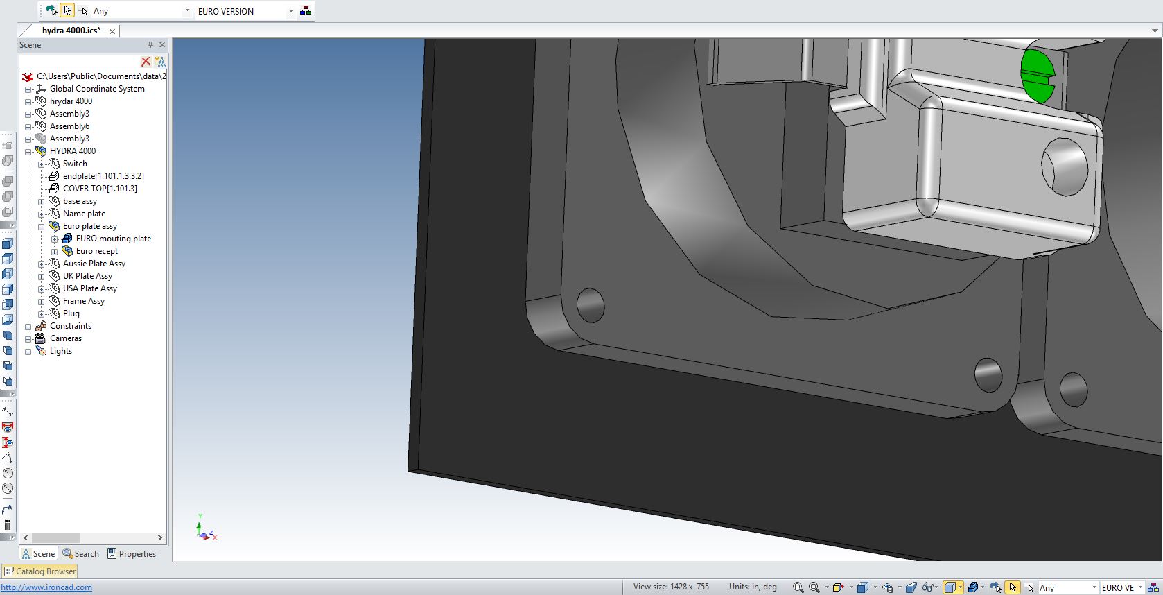
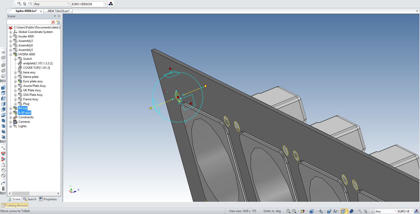
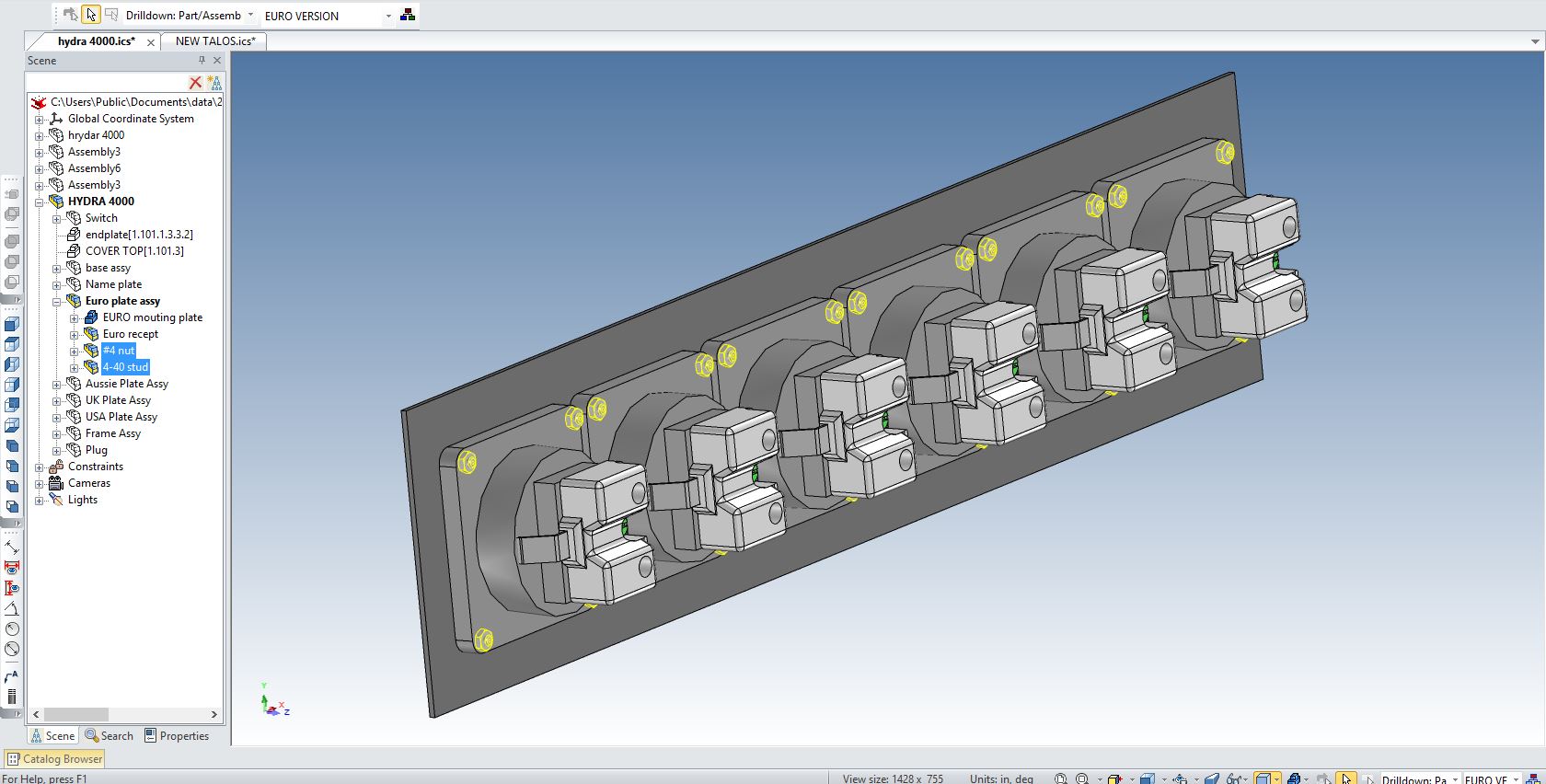
Since they are configured as an assembly we can relocate them and and move them to the appropriate assembly. The studs to the Euro plate assembly and the nuts to the overall Euro enclosure assembly. We will have a basic common assembly and each mounting plate assembly will be added to create the different configurations.
Here are the studs and nuts in the correct location. Again I cannot over emphasize the importance of being able to use the assembly function for associated parts to move or copy.
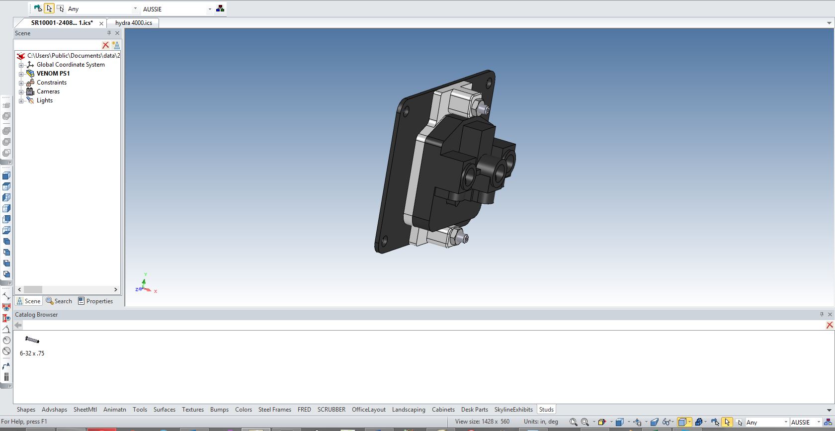
If you design many common parts and assemblies you can have custom catalogs. You can have positive and negative features, parts and assemblies. I have brought up a different assembly that had the required stud for the Aussie plug. I have created a catalog and dragged the stud into the catalog. I could have copied and pasted it, but I wanted to show the catalog function. Notice the stud in the bottom catalog on the left side.
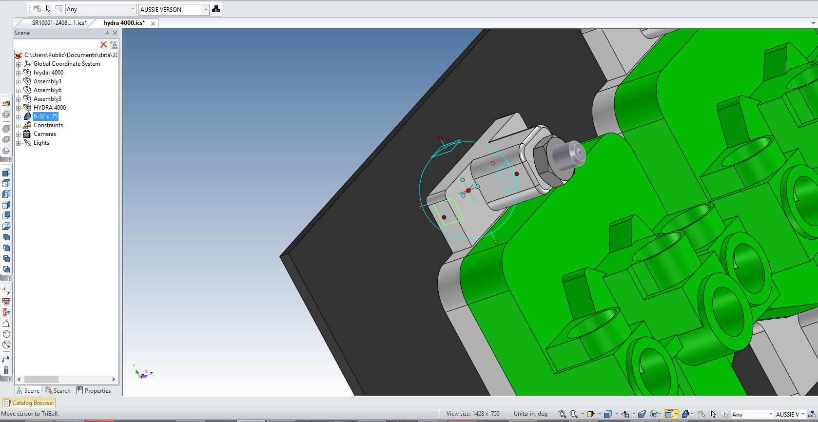
I have dragged and dropped the stud into the scene.
Here is the stud moved into place.
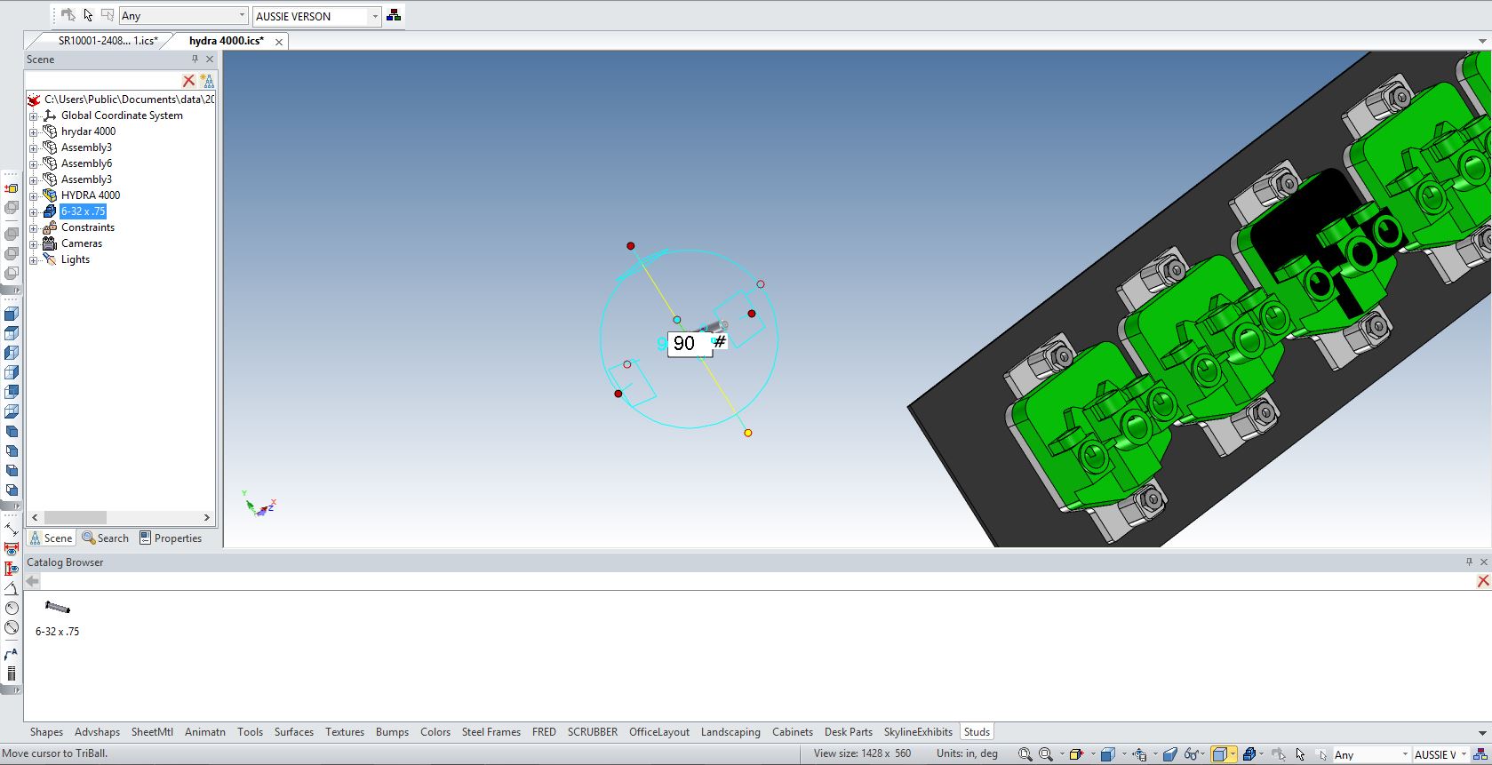
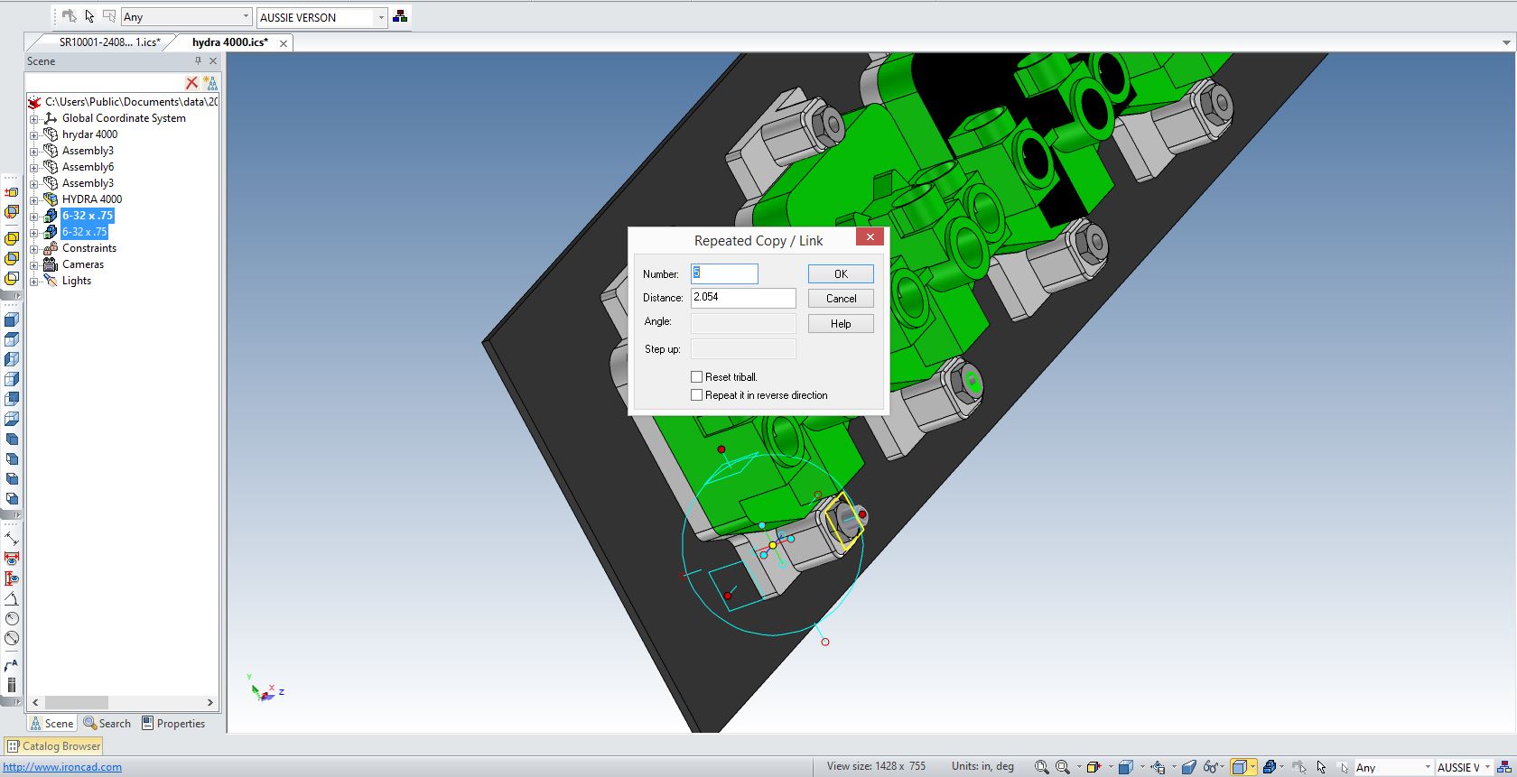
Now we have to link copy. I first link copy to the bottom location. Then link copy to the other locations. Notice I have locked the z-depth of the move by clicking on the top plane of triball (The small yellow rectangle), this will link copy the studs. These will be in their own assembly for any future exploded views that may be necessary. Linking allows any changes to any part will be reflected in the other linked parts.
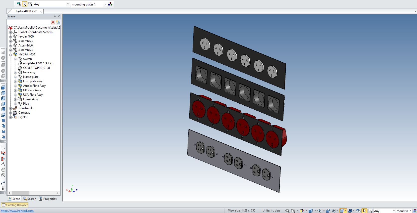
Here are the four mounting plate assemblies in an exploded view. Remember this is a special configuration and does not alter the original locations.
Now we relocate the feet.
Job Complete. Now I did not completely define everything. This is mostly a conceptual configuration for the customer to review. If okayed I would then move to assigning part numbers and creating detail documentation.
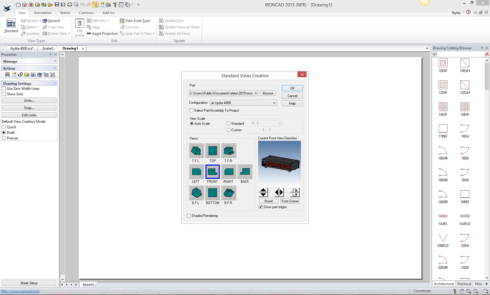
Now I want to put these into a format that is easily viewed. Here is how we create the documentation.
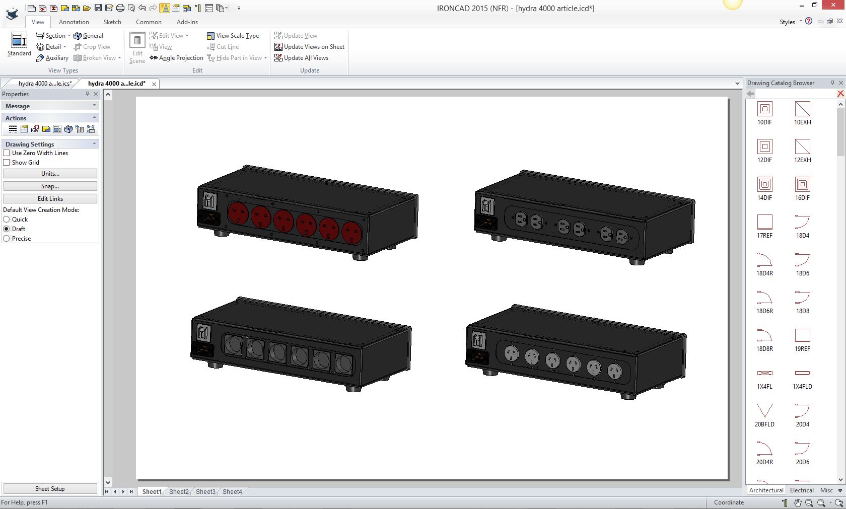
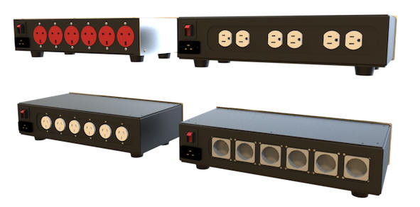
Here are the four configurations put into a clearly understandable document.
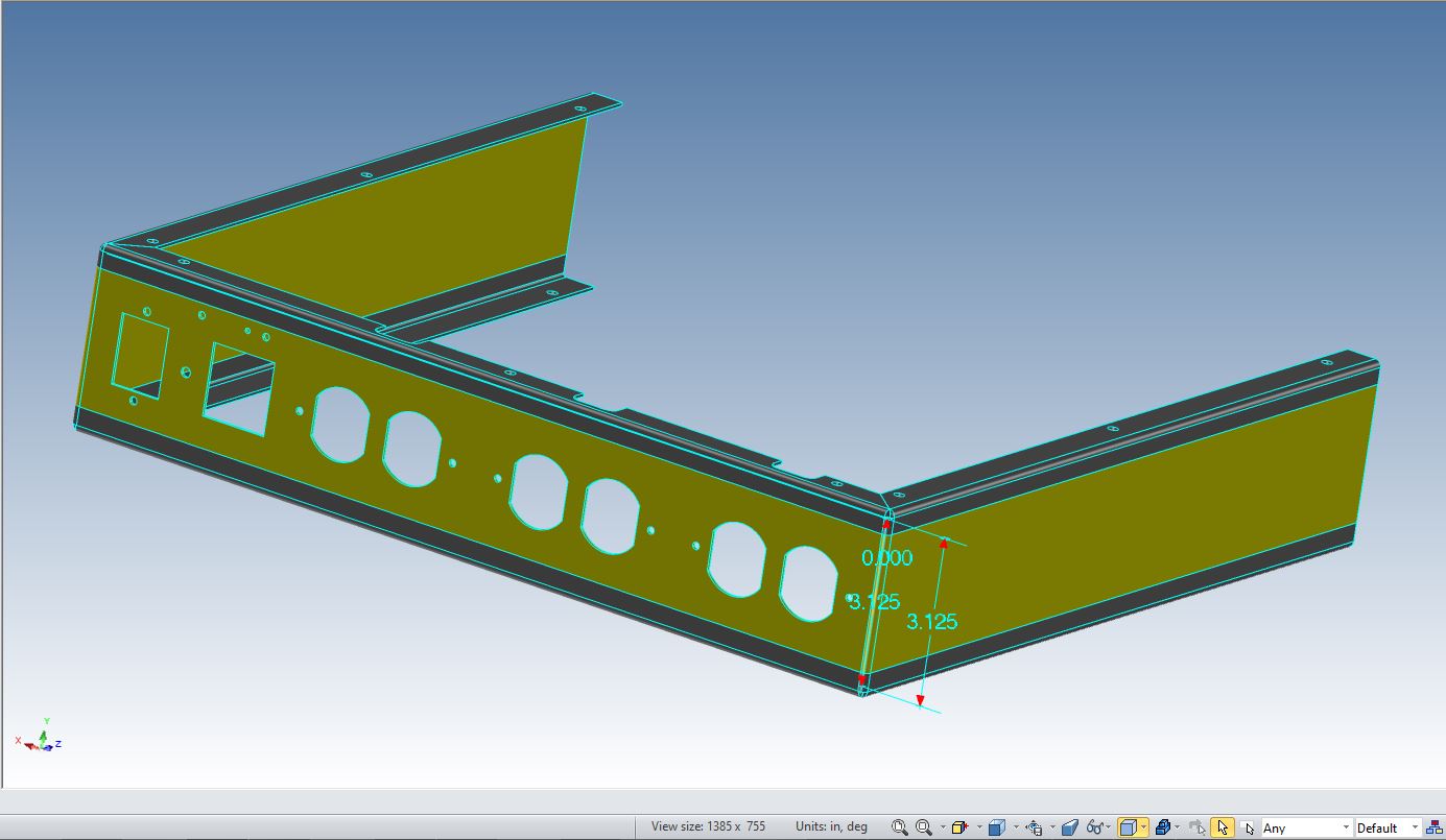
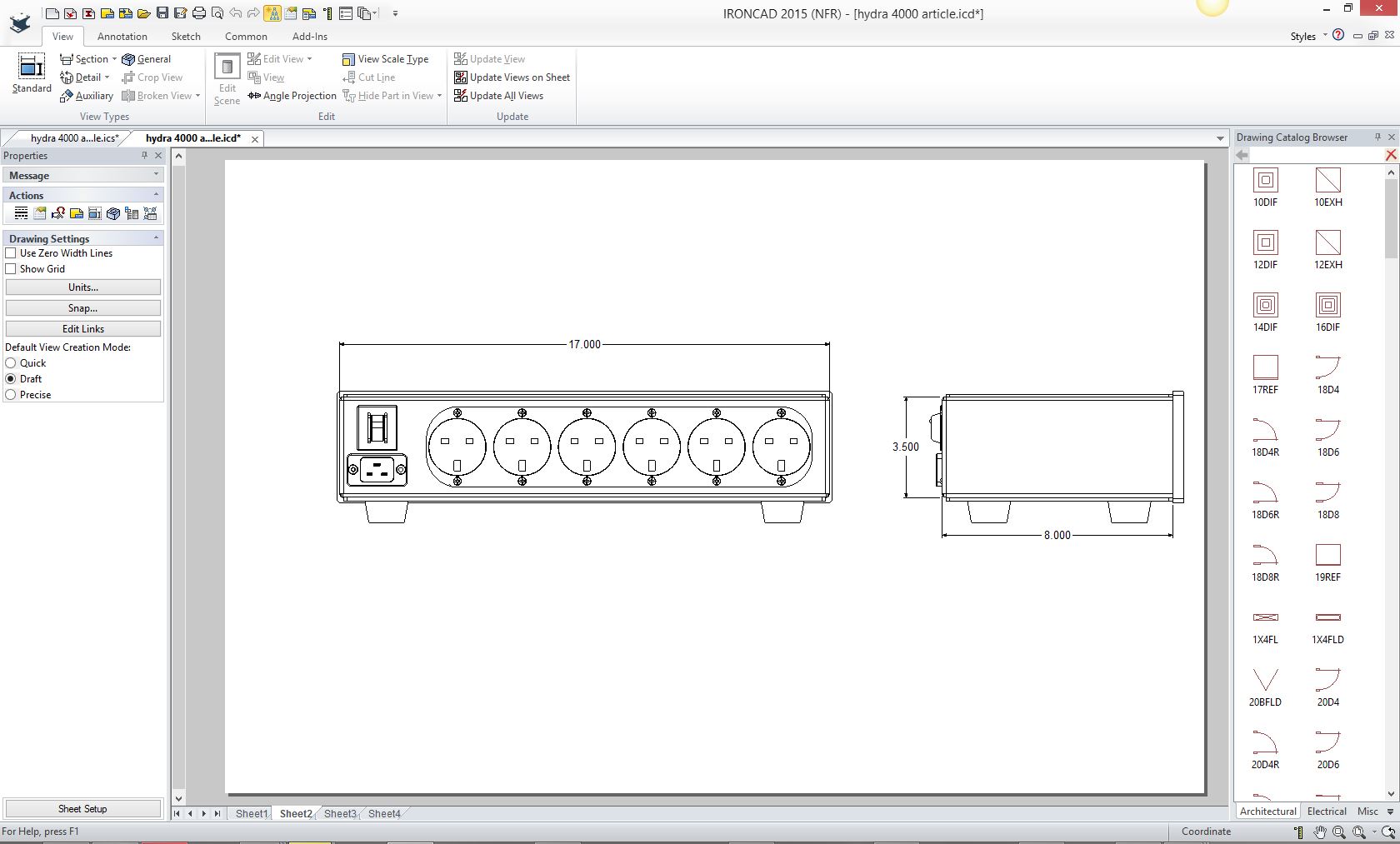
Here is a detailed document showing the overall required dimensions.
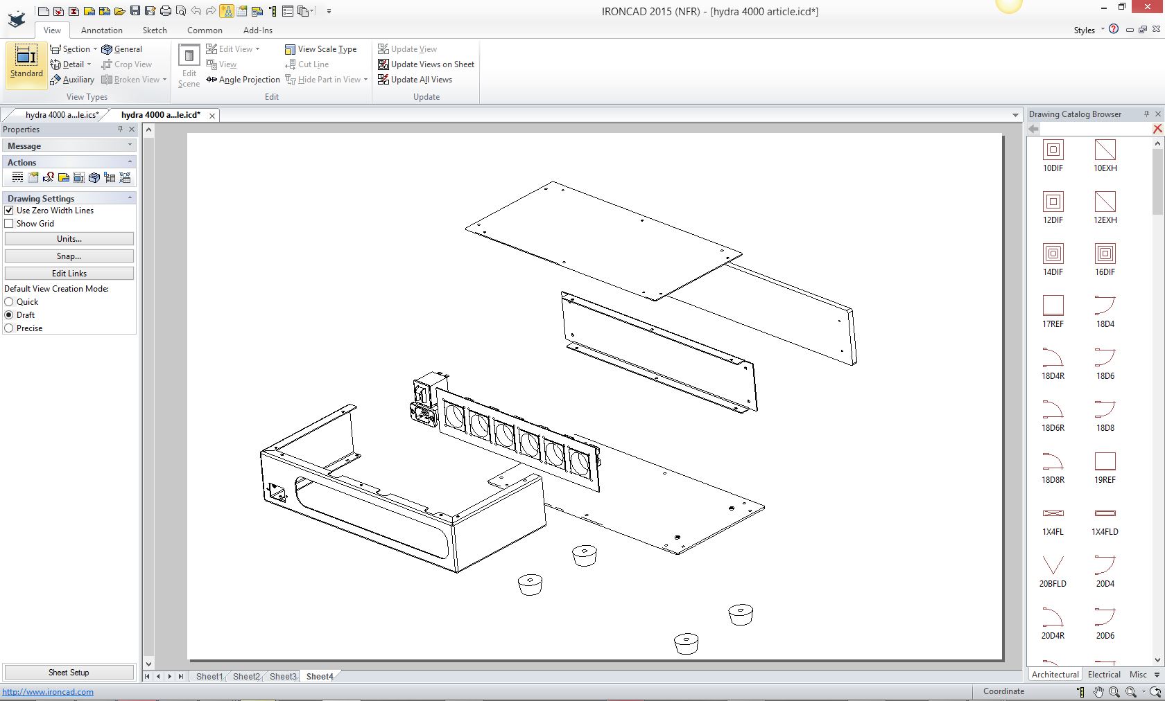
An exploded view of the assembly. The internal parts have been eliminated for confidential reasons.
So there you go. IronCAD does conceptual design easily 2X faster then the Pro/e clones such as Creo, NX, Catia, Solidworks, Solid Edge and Inventor. Where IronCAD really shines, as I have shown you, is it does modifications 5X faster than any of the Pro/e clones Four Functions that Increase CAD Productivity IronCAD vs Solidworks and other Pro/e Clones Even More Productivity! Streamlined Sketching and Feature Based Modeling. I had the opportunity to do some exercises that compared IronCAD to Fusion 360 and Solidworks. But, it quickly changed to a study in 3D modeling techniques. I found that I modeled much differently than the Fusion 360 and Solidworks presenters. I coined my technique Streamlined Sketching and Feature based modeling. These techniques can increase you productivity 30% without even changing your 3D CAD system, 40 to 50% by switching to IronCAD. 3D Modeling Techniques Defined
TECH-NET Engineering Services! If you are looking for a new solution to increase your productivity, take some time to download a fully functional 30 day evaluation and play. Feel free to give me a call if you have any questions or would like an on-line presentation. IronCAD now has a rental plan at $1,500 per year. This will get you into the most product CAD system at a price that will not break the bank. But if your company or consulting firm is a success you can purchase a perpetual version for the reasonable price of $3,970.00 to assure you have access to you engineering data or you intellectual property. See how easy it is to slowly replace you Autodesk or PTC solution with IronCAD. Ironcad Four Functions that Increase 3D CAD Productivity!! IronCAD vs Solidworks and the Pro/e Paradigm Joe Brouwer 206-842-0360 |
TECH-NET ASSOCIATES | RENDERING OF THE MONTH | CAD•CAM SERVICES
HARDWARE | TECH TIPS | EMPLOYMENT | CONTACT