|
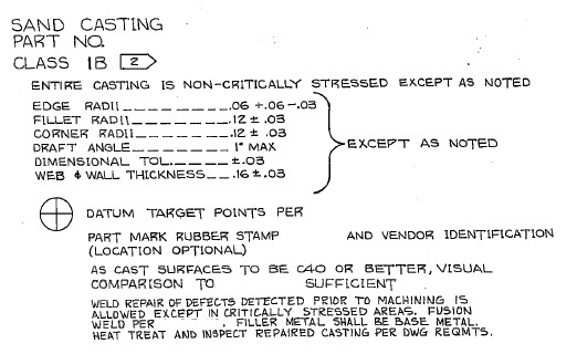
Effective Use of Multiple 3D CAD Systems Many of our jobs require that we work with parts from other 3D CAD systems. Sometimes having only one system available can put you in a corner. Below are a few jobs we have done using multiple systems. Most of these jobs were done years ago. Yes, I was using programs that could easily modify non-native models years, years before many even thought this was possible. Today most of the 3D CAD system offer direct edit functionality and open the door to a much more flexible and productive design environment. Study 12: IronCAD, Catia 5, Scanned Drawing I was hired to do an evaluation of a machined part from an old customer and associate working for a large machine shop. He called and said a large airplane company sent them a drawing and the 3D modeler was finding cavities in the part. This was after two weeks of modeling in Catia 5. They needed the 3D model to do the CNC programing and then machine it. I am not sure if the company has a contract with these folks to convert the drawing and provide the Catia model or just deliver the final part. You have to wonder if the large aircraft company would inspect it or leave that to the supplier. I assure you all standards are out the window. I asked if it was a sand casting and he didn't know. One look at the drawing.
My associate (20 plus years), the quoting person, the company's purchaser, the manufacturing or engineering professional that initiated the request and who knows how many others, never noticed this was a "Sand Casting"? The 3D modeler didn't notice the significance and he had been working on it for 2 weeks. They had to call a person they knew had the expertise and one look saw the problem by just looking at the drawing? Wow, am I worth my money! The drawing consisted of the sand casting and the machining of the casting. No one questioned these two separate definitions? This large aircraft company is a leader in Model Based Enterprise! The model is the design authority!
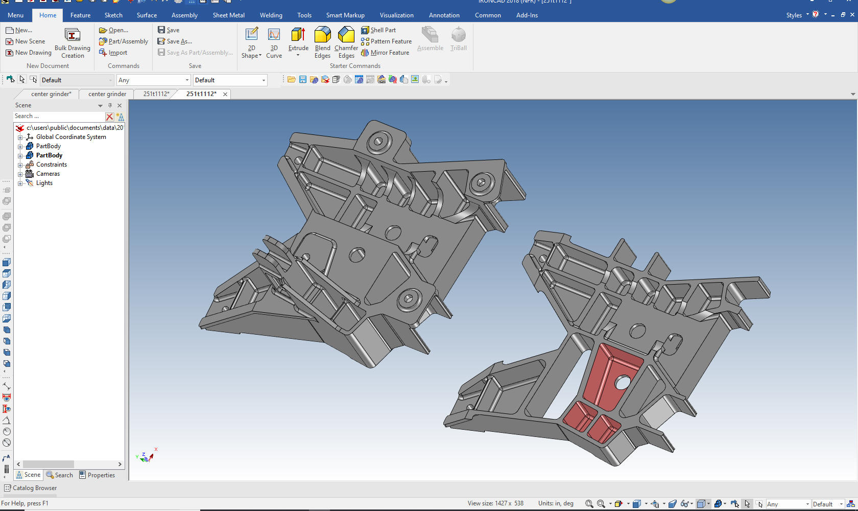
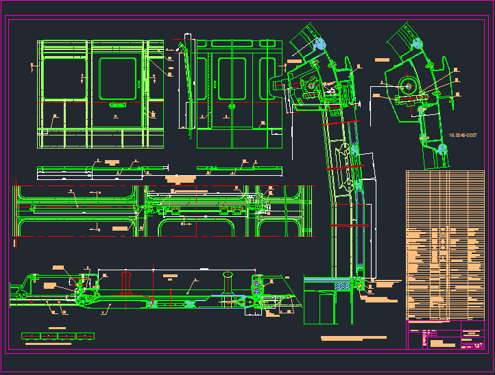
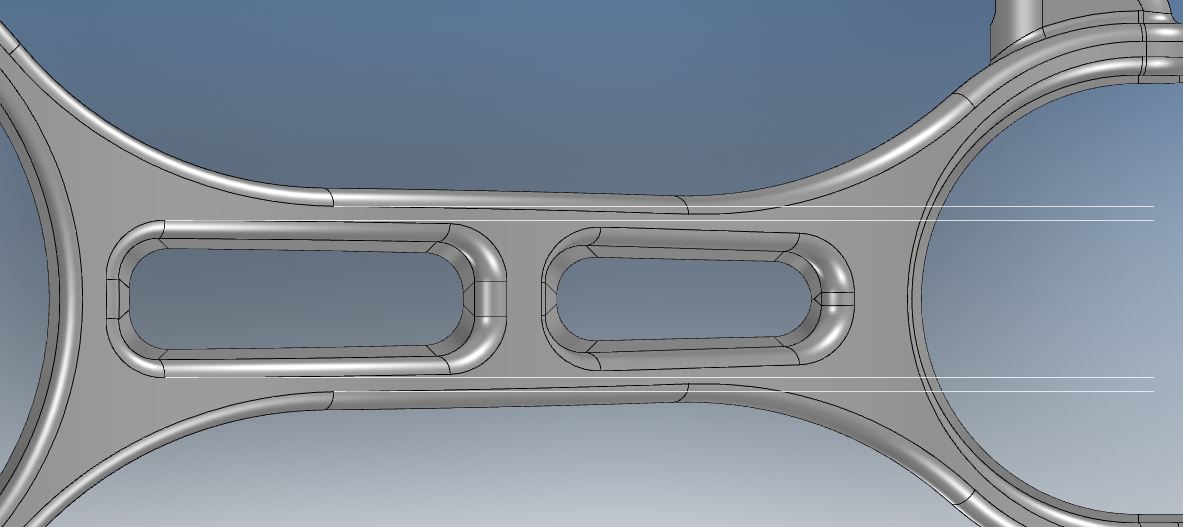
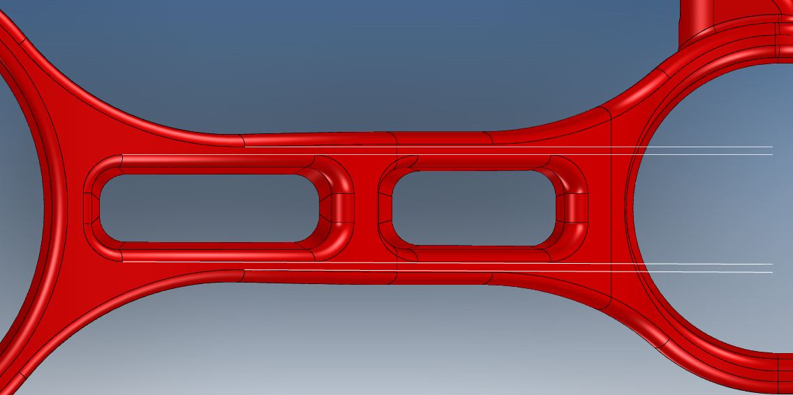
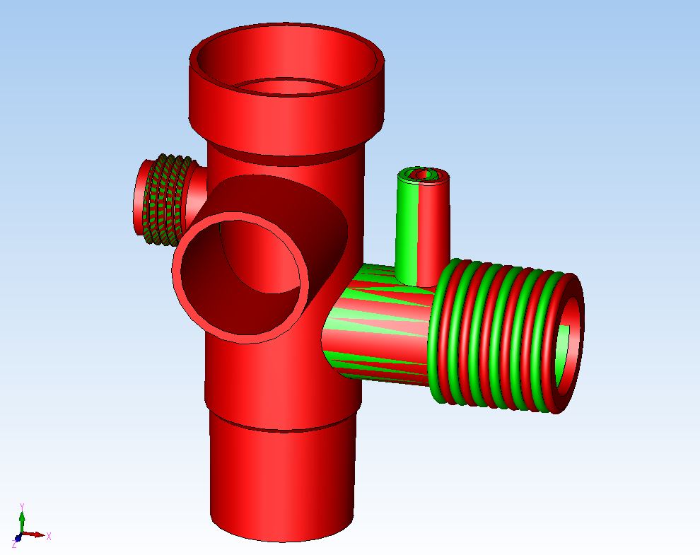
Can the 3D Model Be Used as the Design Authority? Why in the world are they sending out drawings? You would think the company would have a department with a "Standard Process" dedicated to convert drawings to 3D models in Catia to assure they were meeting the model as the design authority. I am sure this would be a great place to put the millennial engineer to get familiar with the products components. It is interesting that the supplier is now required to provide the model. But at what cost? This two day model turned into weeks, maybe a month? Now they have to provide the model, which I saw was done incorrectly. First, they have to check that the model matches the drawing, which it doesn't, then they have to inspect to the model. Uh, who is in charge of this mess. Why does this company depend on the supplier to provide the 3D model in Catia? We can only speculate. But again I note, that they obviously have no standard processes in place. Using the native Catia 5 file, I imported the model in IronCAD and found the cavities. You can see them here in the sectioned view on the right. But I also instantly saw the part was done incorrectly. The errors stood out like a sore thumb. You have to go through a thorough checking when you convert drawings to 3D models. So two weeks already spent. Corrections another week. Checking another week. How many more hours will it take? It took me less than 30 minutes to define the problem. If you need a checker or an highly experienced design draftsman, give me a call!
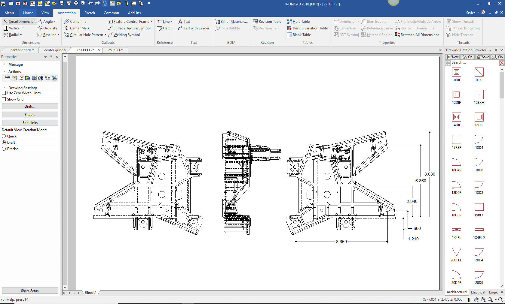
Drawing conversions are much different than designing parts. You have to re-detail the part exactly to check it. There are no short cuts. Murphy is looking play a big part in this process. Here is an AID (drawing) in IronCAD checking the part and with just a few dimensions I found a serious modeling error. You can see this is a very complex part.
Study 1: IronCAD, CADKEY, Pro/E, ZW3D Is it live or Memorex?
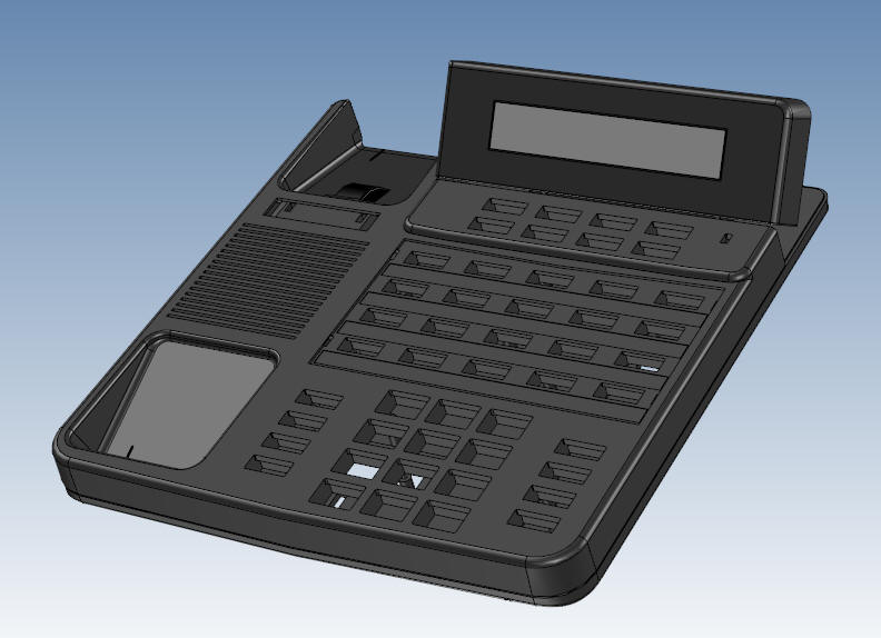
I was brought on a project to help design a new phone system. The original concept was done by industrial designers in Pro/E. We were working in CADKEY since that is what the company was using. With CADKEY we imported the native file from Pro/E and defined the basic configurations (which we had 3) by stripping and recreating surfaces then healing into a good solid. We did an earlier design that was done in CADKEY a decade earlier and we had access to some of the common features we used on that project. We would cut and past the features into the new model, thereby saving design hours. I quickly moved to IRONCAD, which is much better at conceptual design since it has integrated history/feature based and direct editing capabilities. I started adding keyholes and other features, because of its drag and drop, Tri-ball and dynamic push/pull handles it offered fast and easy conceptual modeling with the ability to quickly change the design. IRONCAD has both the ASIC and Parasolid solid modeling kernels, so it was easy to move parts back and forth between the ACIS based CADKEY. CADKEY was a bit limited since it could only directly edit the model and put us in a corner a few times. I also took parts into ZW3D when advanced surfacing was required. Study 1A: IronCAD and CADKEY
I got interested in looking for the old version that was done in 1998. I remember the original files were corrupt and marginally useful. With new eyes I thought I would give it another try. Between IronCAD, ZW3D and CADKEY I struggled through a variety of conversions. From Parasolid, ACIS, STEP and IGES. The top came in good enough to get a good image, the phone hook and display did fine. But the bottom was missing two surfaces that required replacing with the surface function. It would not heal the new surfaces and solid. I exploded the solid into surfaces and even then it had problems with the surfaces. So I exported them as IGES and imported them into IronCAD. First with the ACIS kernel selected, they were brought in as faces, but switching to the Parasolid kernel did the trick and it came in as a good solid. Showing differences in Import Using Dual Kernel and Repair options. Sorry about not including the buttons and the handset, I must have only worked on what is shown. After all it was 20 years ago. Study 2: NX, IronCAD
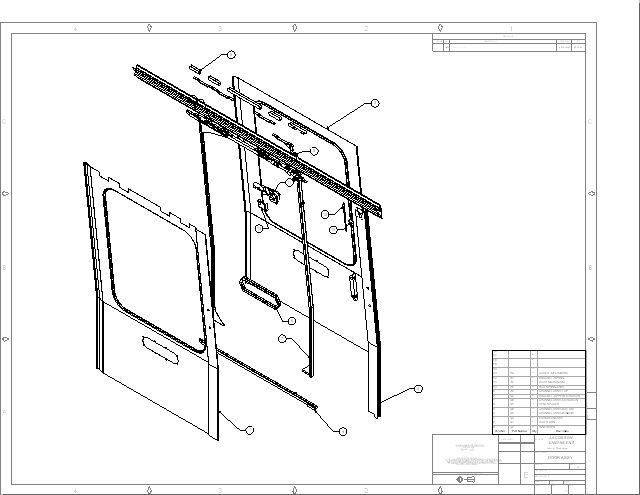
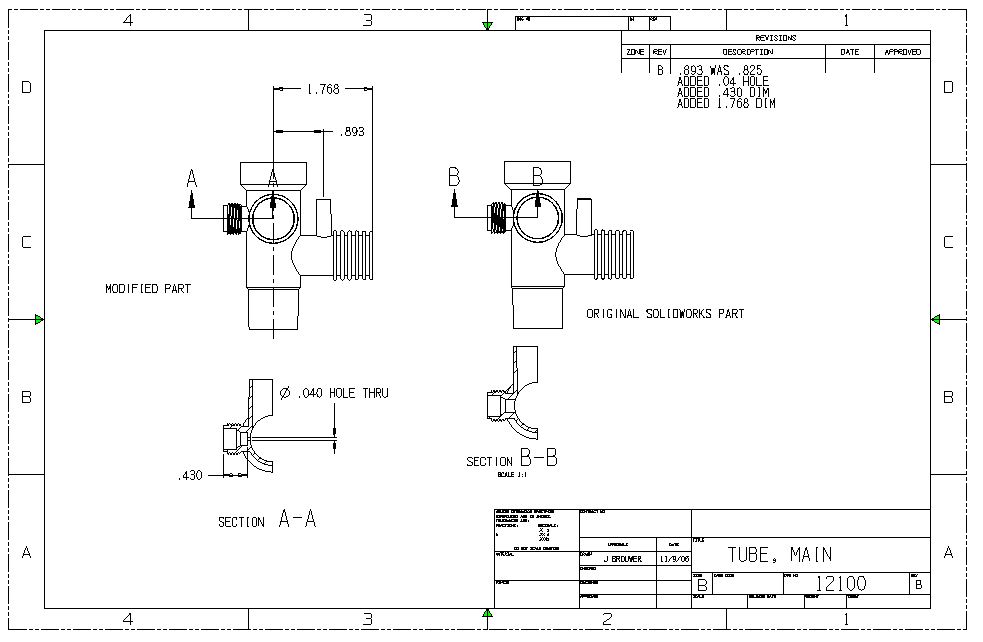
Our job was to provide drawings for inspection of complex parts for a new private jet. These part were originally designed in Unigraphics and we got them in 2006. The models were delivered as parasolid files and the AIDs (drawings) were delivered, wait, jpegs! Yup. I have no idea why they didn't use PDFs. This was the beginning of the MBE (Model Based Enterprise) experience. Minimized GD&T. Today, most suppliers work around this convoluted level of engineering documentation. It truly is a joke, costing billions. Our job was to provide as many dimensions as we could to aid inspection. At the time the company was not prepared for this lack of detail. Many of these parts were almost impossible to detail. Without having to detail the parts the design was basically freeform design. Sadly, that is where the new 3D CAD management is allowing this to go. Now, PMI (Product Manufacturing Information), being basically a 3D drawing offers even less checking and review. But many of the designers are checking their parts by detailing then generating the virtually useless PMI. I have to say even with the minimized GD&T, delivering the documentation as an AID (drawing) made this job much easier. You do not know how convoluted can get until you see PMI. Those that demand PMI have never done it. Take a look. You can see there is no standard and they are winging it. Original AID with minimized GD&T and a few overall dims.
Here is the detailing of the above part that we provided the client. Just enough to aid in inspecting the parts. We had hundreds of parts to detail.
The company that was contracted to make these parts had a myriad of high end CAD systems, since it does business with some of the largest aerospace companies in the world, but no one could use then. We import these parts into iRONCAD and created the drawings. We are still fighting with incompatible formats that make our suppliers jump through expensive hoops. It is time to completely review our engineering to manufacturing process.
The Space Between Engineering and Manufacturing This was truly a fiasco. I truly think all of the designers were from automotive and only hired for the UG experience. Study 3: IronCAD, DXF, ZW3D
What I am saying is that it is really nice to have a couple of different CAD systems to enhance your modeling capabilities and increase your productivity. It is not hard to learn another system. I personally have a bit of trouble with the Pro/E design paradigm, with the heavy constraints and having to create a plane and sketch, separate part and assembly workspaces, but I am getting used to it. I do prefer the ease of use of IRONCAD and ZW3D. Give us a call and we will give you a brief description of the products we sell and how they differ.
Study 4: IronCAD, Solidworks, ZW3D
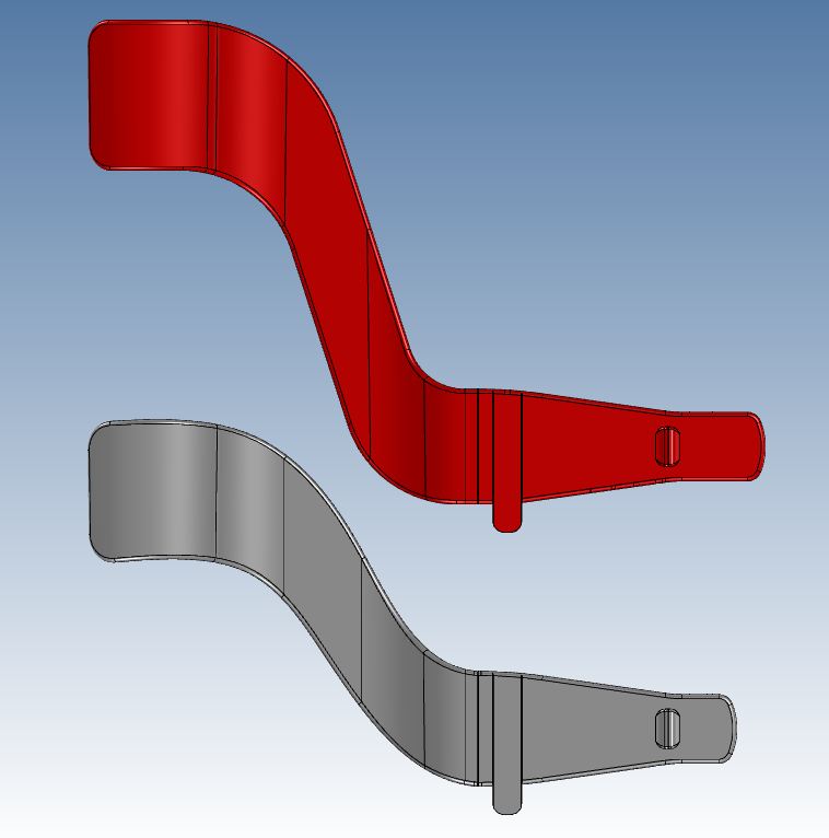
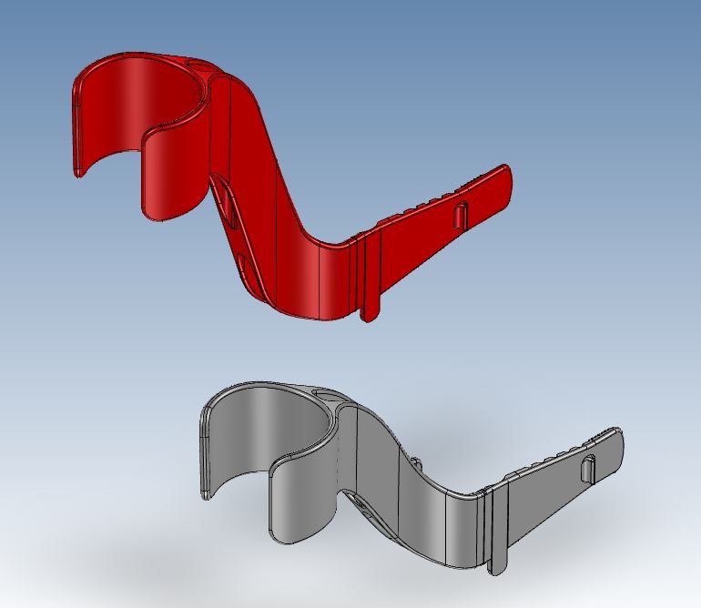
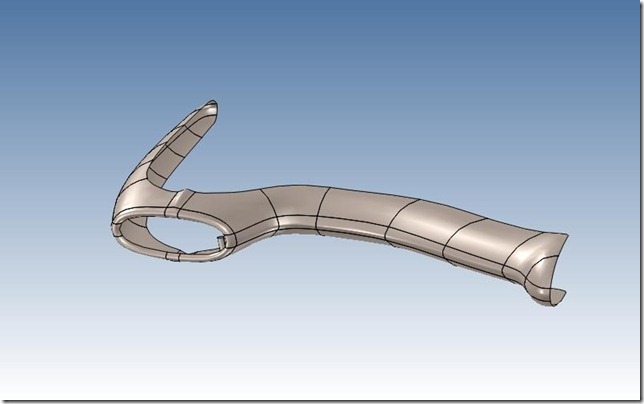
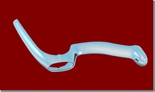
A customer came to me from a recommendation with a Solidworks project. He wanted to make this strap taller. I asked him why he didn't get the original designer to do the modification and he said he couldn't get to it in time. I then told him I didn't have Solidworks and would have to do it in a different program. He just asked "Can you get the job done fast?". I imported the native Solidworks file into IronCAD and started modifying the part. In doing the job, due to the extended length, I noticed that this draft was causing some problems. I soon realized that the Solidworks part had the draft originating from top plane of the part. For the original part this was a slight change and would probably not be noticed but with the increased height this would be unacceptable. I could not create the necessary draft from the diagonal face in IRONCAD and moved the part to ZW3D which had this capability in its surfacing package. See the difference below. The original part
The revised part.
Now remember this was Solidworks 2006 so I don't know if it has the capability now. It was a benefit to have another package available. Here is another rendering showing both parts.
Study 5: IronCAD, Solidworks
This was another job from the same customer as above. I imported the Solidworks part file directly and edit the part by extending the tube with the boss and reducing the size of the hole in IRONCAD. It just took minutes to modify. But as you can see I can work with any program. This is the advantage of working with a program that can directly edit the part. As I have said before IRONCAD/INOVATE are the only programs that have both history/feature based and direct edit modeling integrated in the core of the program. Here are both parts.
Study 6: IronCAD, CADKEY, Rapidform, Alias Surfaces
REVERSE ENGINEERING SUCCESS! I took on this 1959 Corvette bumper reverse engineering project. Using this particular method, the procedures involved in the original product don’t have to be known in order to analyze the end product, making this quite a convenient resource! For the full story take a look at the link above. Here is the original scanned part. It was scanned and then modified to create usable surfaces. The conversion was done in Rapidform.
We did the basic work in CADKEY, but we hit the limitations of it surfacing capabilities and had to have an Alias advanced surfacing expert finish the job. Here we have the final bumper! Perfection!!
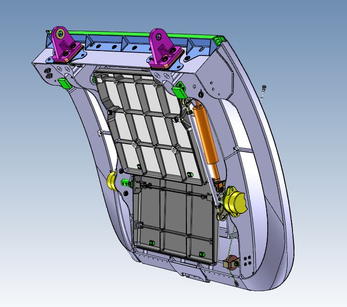
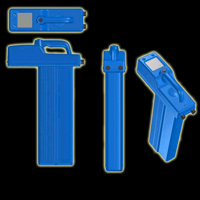
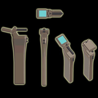
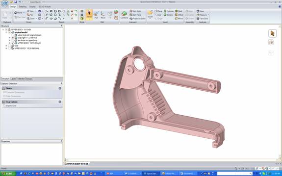
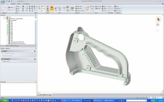
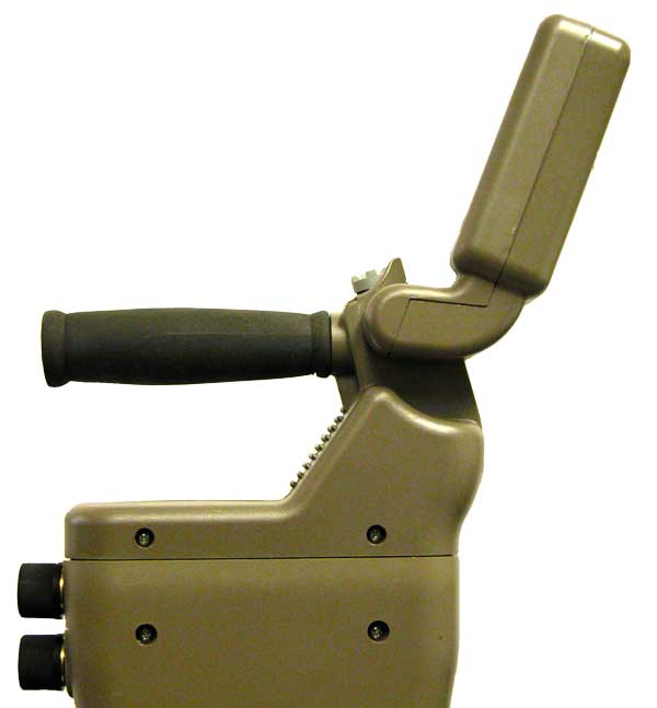
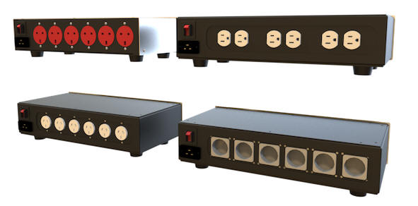
Study 7: IronCAD, CADKEY, Solidworks, SpaceClaim This project was originally designed in Solidworks. As in the story the original designer became sick and could not continue and I was contracted for the job. Click the above link to read the complete story. Solidworks Original Design Final Design
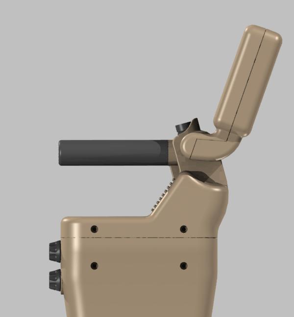
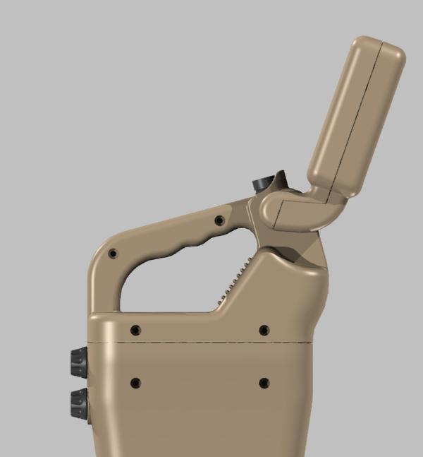
Since I could use the Solidworks data and directly edit it, I completed the original job in CADKEY and IronCAD. But I found this design a bit clunky and talked Prototek into a redesign. They wanted the monitor to be able to rotate for better viewing, and as you can see above it is a much more appealing product. A couple of years later Prototek came to me with a request for a new design. We got the old data and started modifying the design using direct edit. The redesign took 6 hours. Click the above link to see the complete story. Original Design New Design
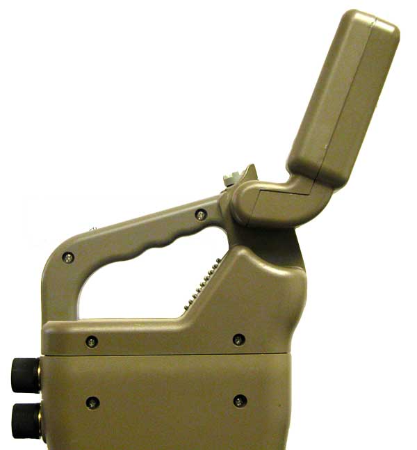
Is it live or is it Memorex? Here are a couple of realistic renderings plus pictures of the final product and the new redesigned product. The renderings were done in IronCAD. Click the above link for more renderings. Original Design
New Design
Study 8: IronCAD, CADKEY IronCAD's move face functionality has greatly improved in the past few revisions. I used to depend on CADKEY to do much of this kind of design in the past. I would jump between systems just to save a half hour. Both systems have robust direct edit and I can easily move parts between systems. But IronCAD is basically a much more user friendly, flexible and productive system. Now I rarely go back to CADKEY.
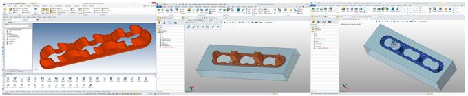
Study 9: IronCAD, ZW3D, Autodesk Inventor Reverse Engineering 2015 AK-47 Project This was my first chance to use ZW3D's robust reverse engineering functionality. As you can see it was a great success. But a couple of the parts came from Autodesk Inventor native files that I found on line. I used both ZW3D and IronCAD in creating the parts. 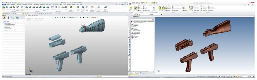 Study 10: IronCAD, ZW3D Core/Cavity Split in 5 Minutes!! We do quite a bit of plastic product design. It is a great help to have the ability to create a core/cavity split to check your parts. Many time I find an error in my design prior to detailing and release. ZW3D Mold design is so easy even a product designer can do it.
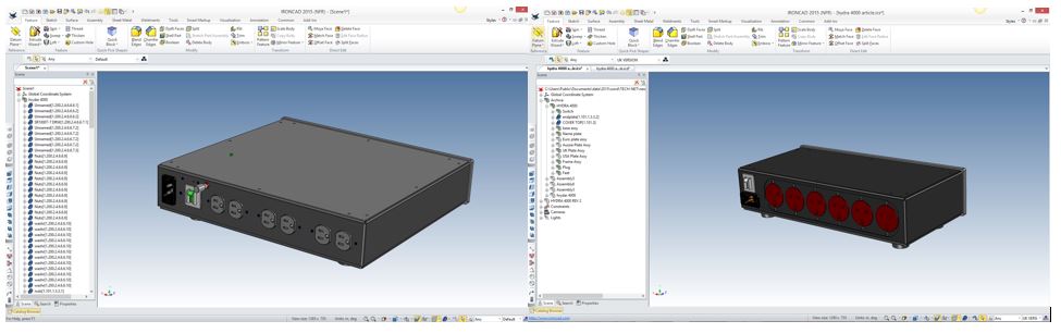
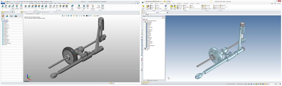
Study 11: IronCAD, ZW3D 3D CAD Systems Working Together I first created this assembly to sharpen my skills with ZW3D. I find that creating many parts from drawings is the best way to learn a 3D CAD system. Then I decided to use it to show the incredible interoperability between IronCAD and Inovate (Modeling Only) and ZW3D Lite (Fully Functional 3D CAD). You can see in the article above that it was a total success.
|


TECH-NET ASSOCIATES | RENDERING OF THE MONTH | CAD•CAM SERVICES
HARDWARE | TECH TIPS | EMPLOYMENT | CONTACT