|
IronCAD is unique and the most productive
conceptual 3D CAD system. Change is incredibly easy. You can have
several iteration of your design in the same file.
- Single Model Environment - Parts and
assemblies in a single file
- Drag and Drop Design from Custom or
Standard Catalogs
- The Only Integrated History/Direct
Edit Design - Both used in your design process
- Copy and Paste Directly from Different
Files
- The Incredible Feature, Part and
Assembly Manipulator - The Triball
We have the native IronCAD and STEP File Available here for download
Note: IronCAD Model .ics/AID .icd native
files must be copied to the same folder.
3D Modeling is the basis for our
engineering. That is the only place where productivity is paramount.
You can have all the PLM/MBE gurus debating data management, but it
does not add one smidgeon of productivity to the design process.
Top down or In-Context modeling is the most productive
feature of 3D CAD. Most systems tout this but each part is still an
external part. We are talking about a single model or multi-object
design environment. Both of the systems we represent offer this as
the "normal" design process. Thereby increasing your productivity 20
to 30%.
In these exercises I not only focus on modeling techniques, but
also on much more productive systems to do our designs. I hope you
enjoy them and learn something. If you are in management, understand
that all 3D CAD systems are not the same. Cutting your engineering
costs is very simple. Even your legacy data is not a problem. Please
feel free to give me a call. There are millions of man hours wasted
every day with poor modeling techniques and dated 3D CAD
systems that cost a fortune. Productive 3D CAD systems do not have
to be expensive.
Joe Brouwer
206-842-0360
I am doing the below assembly for
an exercise showing my modeling techniques and, of course, my 3D CAD
solutions.
When I introduce IronCAD's very
flexible design paradigm I have a hard time to get the Pro/e clone
users, like Solidworks and other programs to understand the drag and
drop design paradigm.
I saw some video challenges on linkedin and thought I would give it a
try on IronCAD. This will give you an idea how different
and flexible IronCAD is compared to the conventional Pro/e clone and
to the not so conventional Fusion 360.
These exercises started out to show the benefits of IronCAD over Fusion 360, but
quickly turned into a study of modeling techniques. Take a look at all of
them, they will open your eyes to a much different and more productive way of
modeling. It really has more to do with modeling technique than it has to do
with the 3D CAD systems. I have found that I do 3D modeling as compared to
the conventional 2D sketching. Of course, having a more productive 3D CAD
system doesn't hurt.
See the
comparison with many other 3D CAD systems.
3D CAD Modeling Techniques
These exercises were incredibly
popular and I thought I would follow up by showing more examples of
this 3D modeling technique.
We will be doing a
couple of parts each weekend in both IronCAD and ZW3D. I hope you
enjoy these exercises and hopefully they may lead to increasing your
productivity.
Please feel free to review the first
lesson:
3D Modeling Techniques IronCAD Lesson One
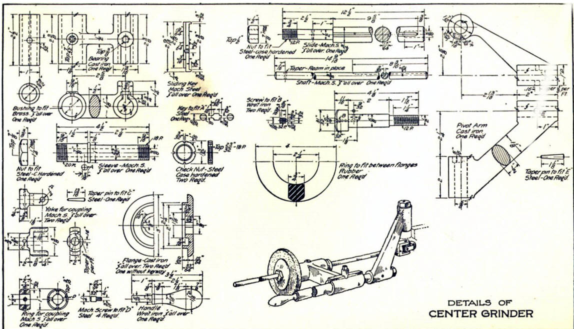
I was a bit short sighted last week with the Bearing. I
named the file "Bearing" when it should have been "Center Grinder".
There is a couple of ways to get the Bearing into another file. You
can import it, copy and paste from another file or just rename the
file. I had a document attached and I want to keep that document
tied to the related model file so I will have to
save it as the new name.
I bring up the document file:
Bearing.icd
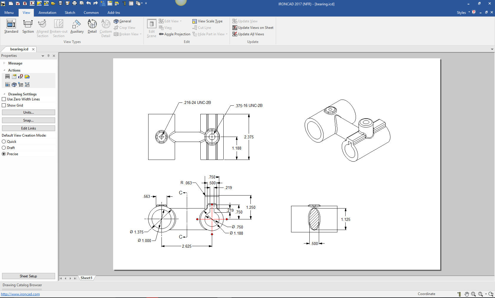
I right click on a view and select edit scene.
It will bring me to that configuration in the model file and the relative view.
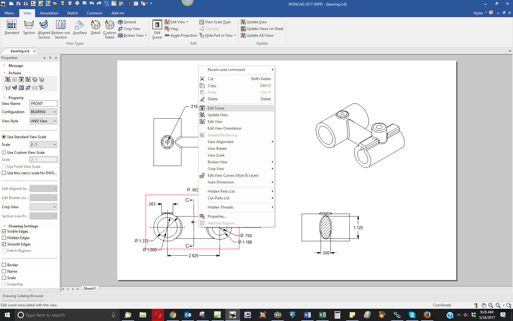
Now we have the related scene and
configuration. Why scene? IronCAD was based on a graphic design
package called "Trispectives" and scene would be appropriate. That
is why IronCAD has integrated realistic rendering and animation. Why
configuration? IronCAD is a single model environment and you have to
be able to reference the different parts and assembly for drawings
and other modeling functions. Especially when you do many
different iterations of a design.
We now see the Bearing.
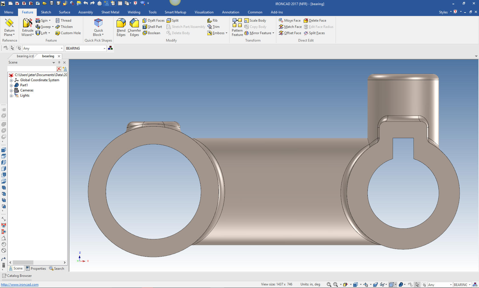
But now we have to save it as "Center Grinder" It gives us an option
to relate the existing bearing document to the new "Center Grinder"
model file.
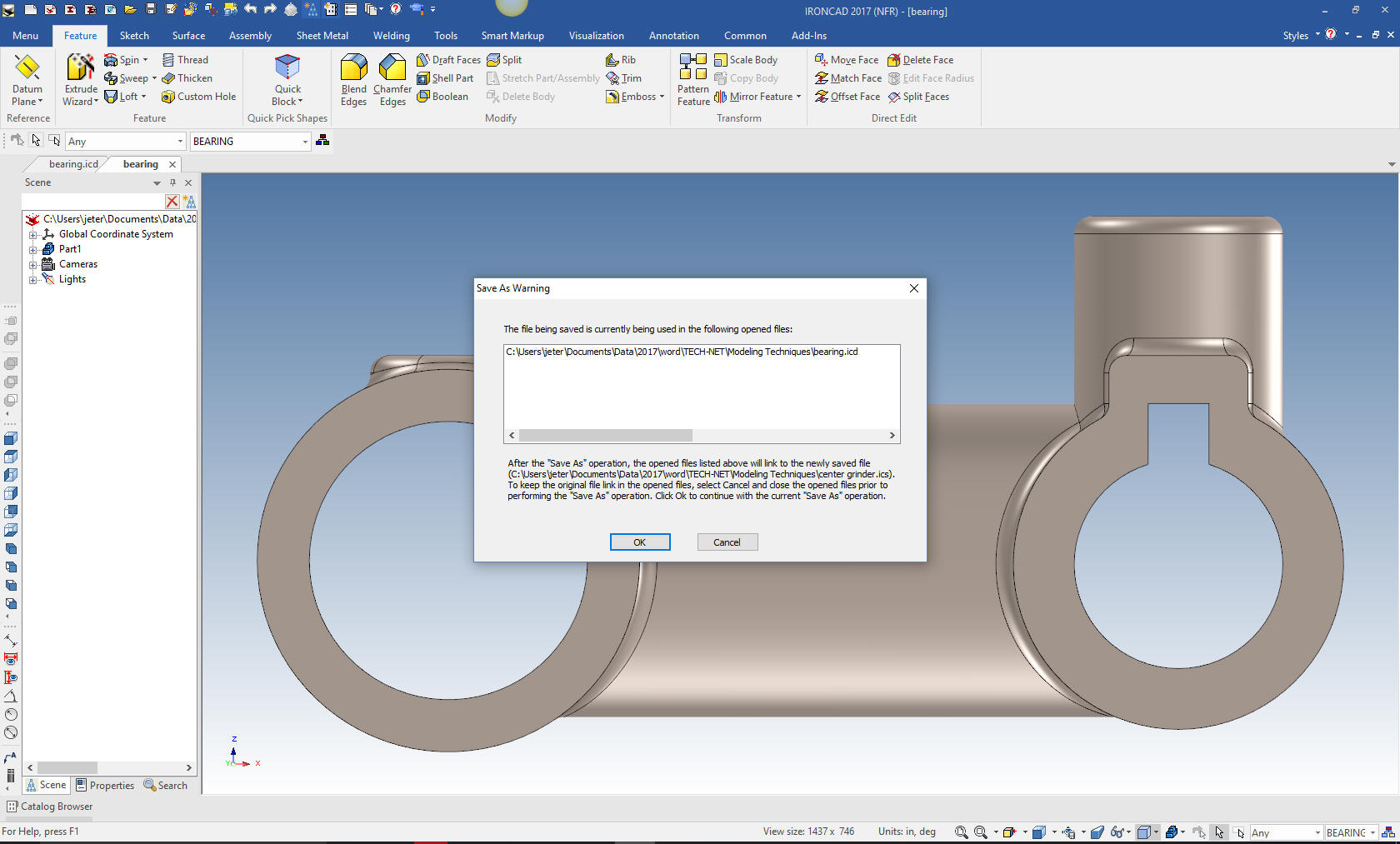
I will save the bearing document file to
"Center Grinder.icd" so as not to forget. Now we are ready to start
adding parts. We will not detail the parts until the end.
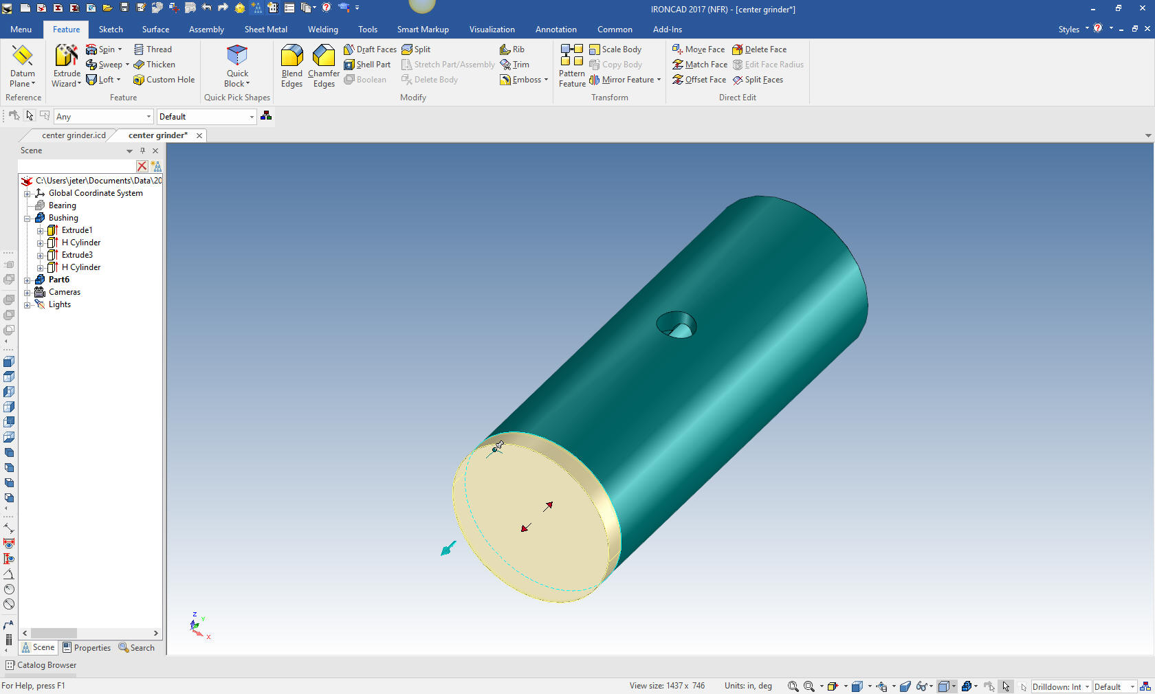
The
first part we will create is the Bushing. We will start by using the
Extrude Wizard and selecting the mating face. We are going to design
these parts in context or top down in the single model
environment. We will change the configuration to default until we
are ready to make the drawings.
We select the face of the
left cylinder add select standalone part.
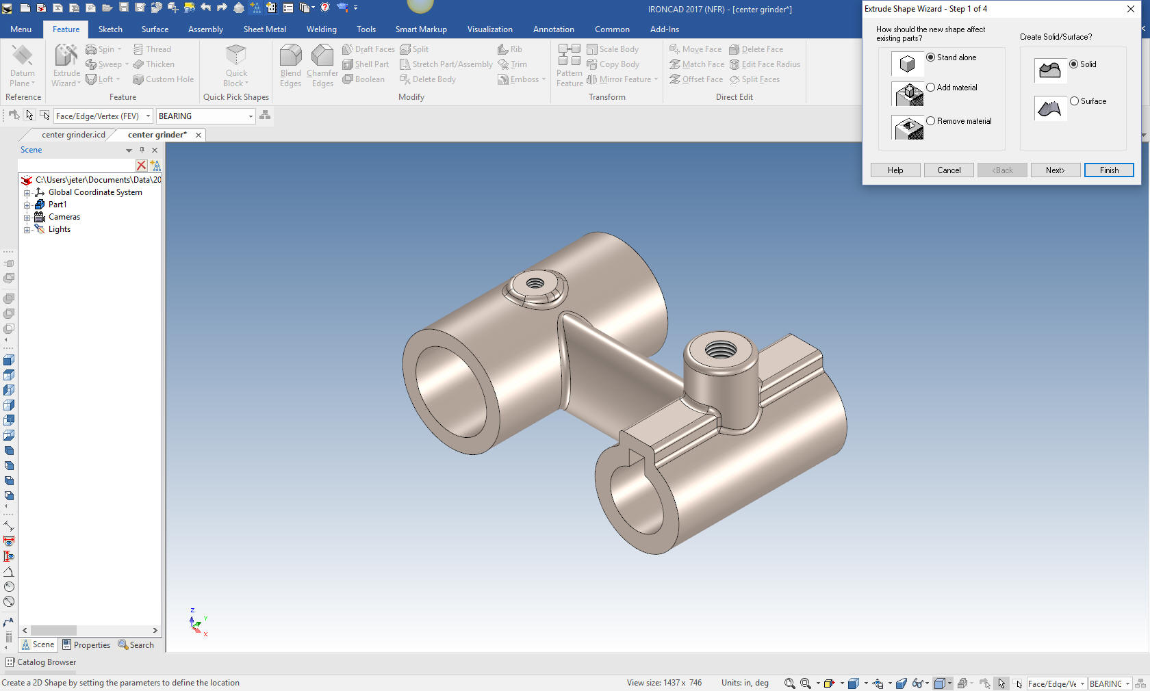
This will bring up a sketching plane. Yes, when designing in context
is it much better to use the extrude wizard to project
mating edges.
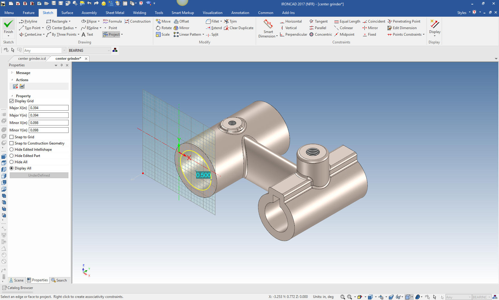
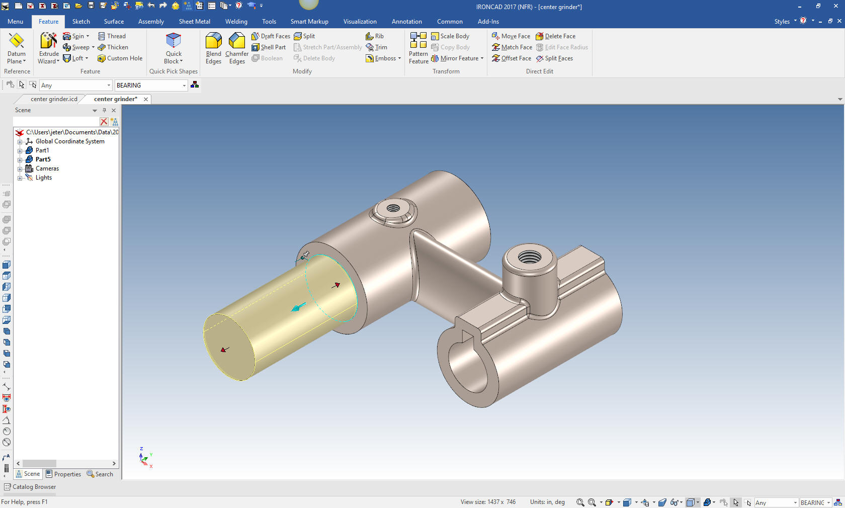
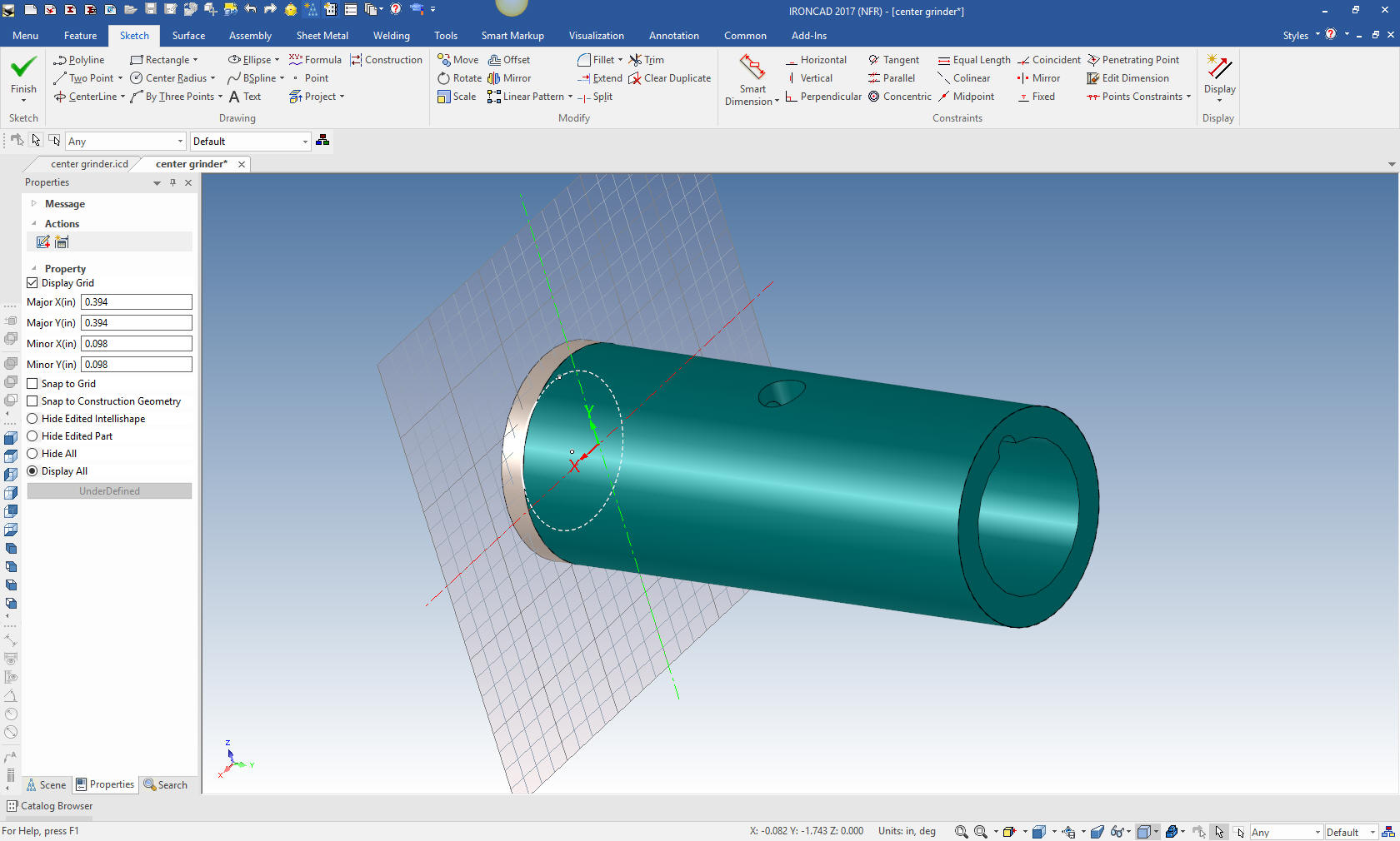
We
select okay and we have our extrusion. But now we have to size it. A
couple of things happened when I did this. I didn't set a direction
or length. I will do that as I size the bushing. If you look at the
scene browser (history tree) you will see a new part created. I am
going to size the bushing change the colors of the parts and rename
the parts in the scene browser.
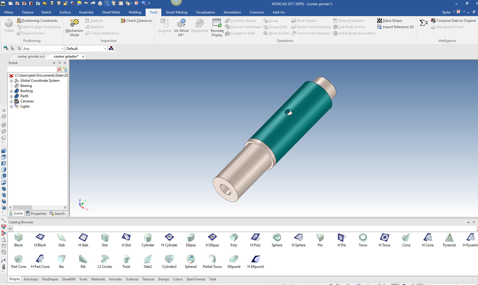
We
drag a hole cylinder to center of the bushing and size it.
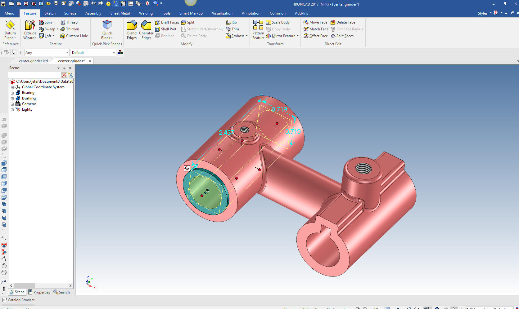
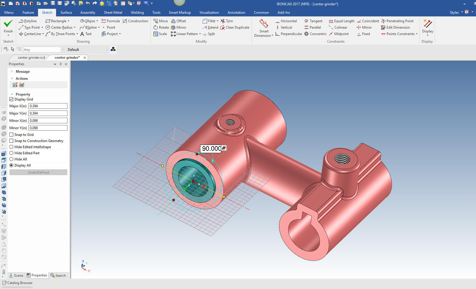
I
have aligned the bushing so we can add the hole. We do this again
with extrude wizard while the two parts are assembled. We position the
plane on the face of the bushing and rotated it with the triball.
Now we project the hole in the bearing onto the plane. Edit the
radius.
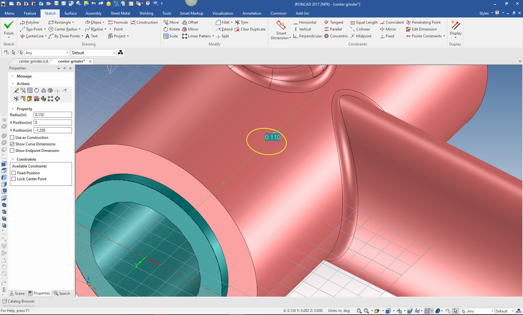
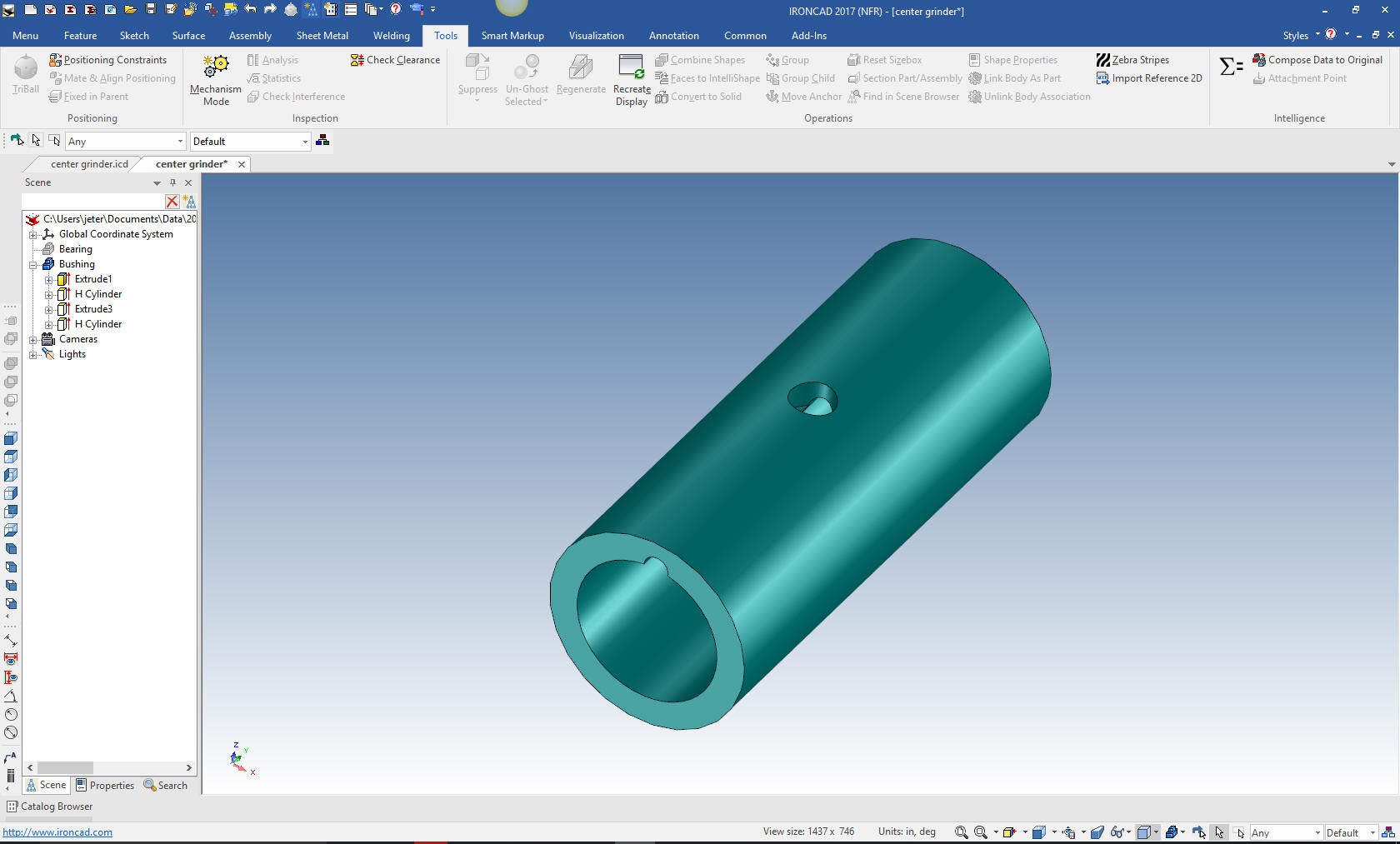
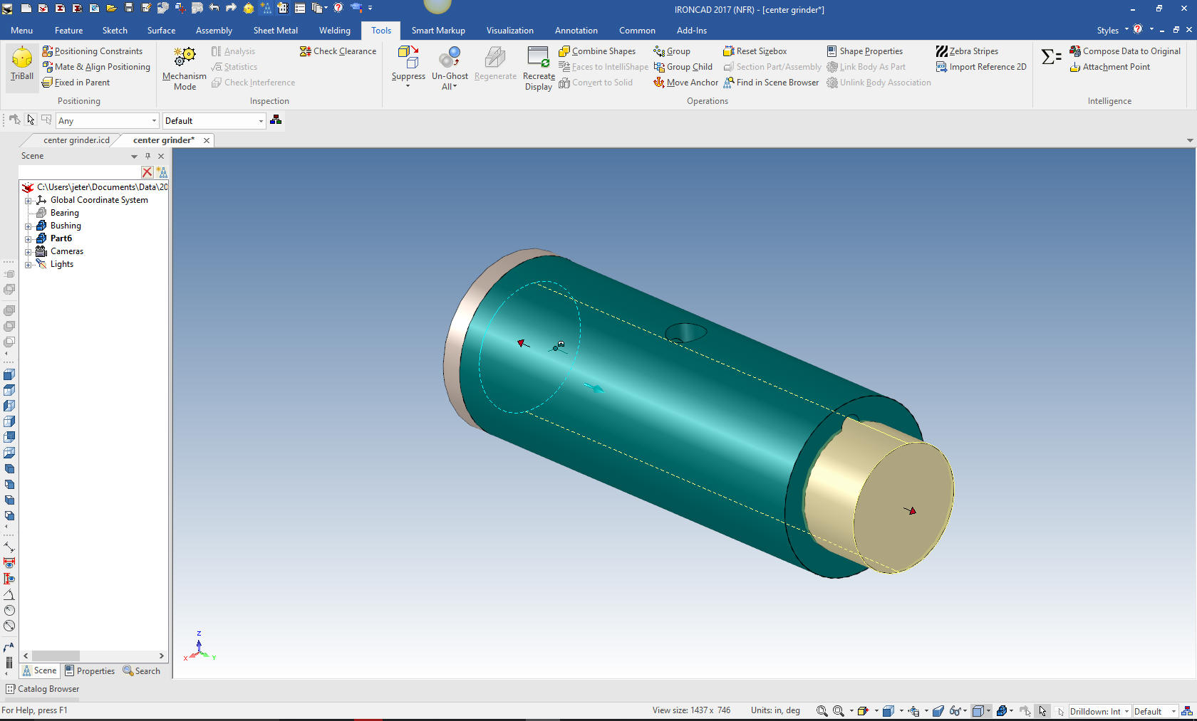
We
will now hide the bearing and add the oil groove by dragging and
dropping a hole cylinder, locating and sizing it. We are done
with the bushing.
Note:
These parts are in aircraft position. This was a concept in very
beginnings of 3D CAD while at Boeing. All of the parts were designed
in their position in the airplane. I was instrumental in bringing
CADKEY on board at Boeing. We would import/export parts to and from
Catia with IGES. The parts "had" to be in aircraft position.
The 1980's - 3D CAD - The Beginning
Now for the Sleeve. Again I select the extrude wizard and project
the edge of the bushing to create the middle cylinder. As you can
see you do not have to worry about inserting a part and aligning it.
It is done at part creation. The time saved in this step alone has
to make you start thinking about design productivity.
Now we
need the far side shaft which again I will use the extrude wizard. I
will project the ID. But I need to create a full circle. I really
doesn't matter where I establish the plane since I can resize it
without a consideration.
We
have sized the shaft and now for the other side.
We
will create the front shaft by dragging a cylinder to the center of
the face size it and then drag a hole cylinder to the center of the
new Sleeve. We can use a mixture of drag and drop, projecting and
sketching as we decide which is the most productive.
We
need a hole for a small key. Again the extrude wizard is brought
into play. We rotated it to horizontal and sketch the circle.
We
select okay it automatically creates the hole. We will size the
hole.
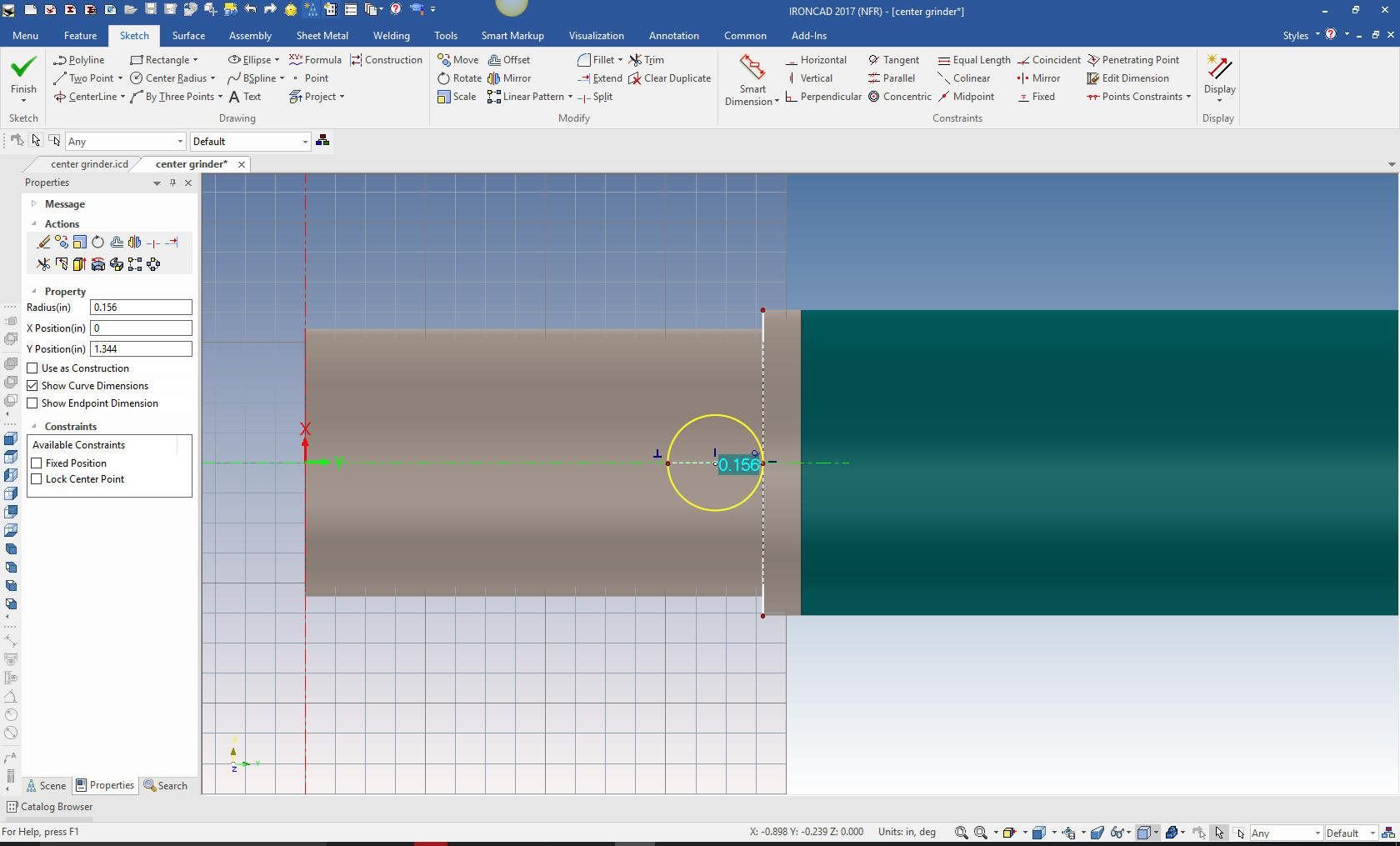
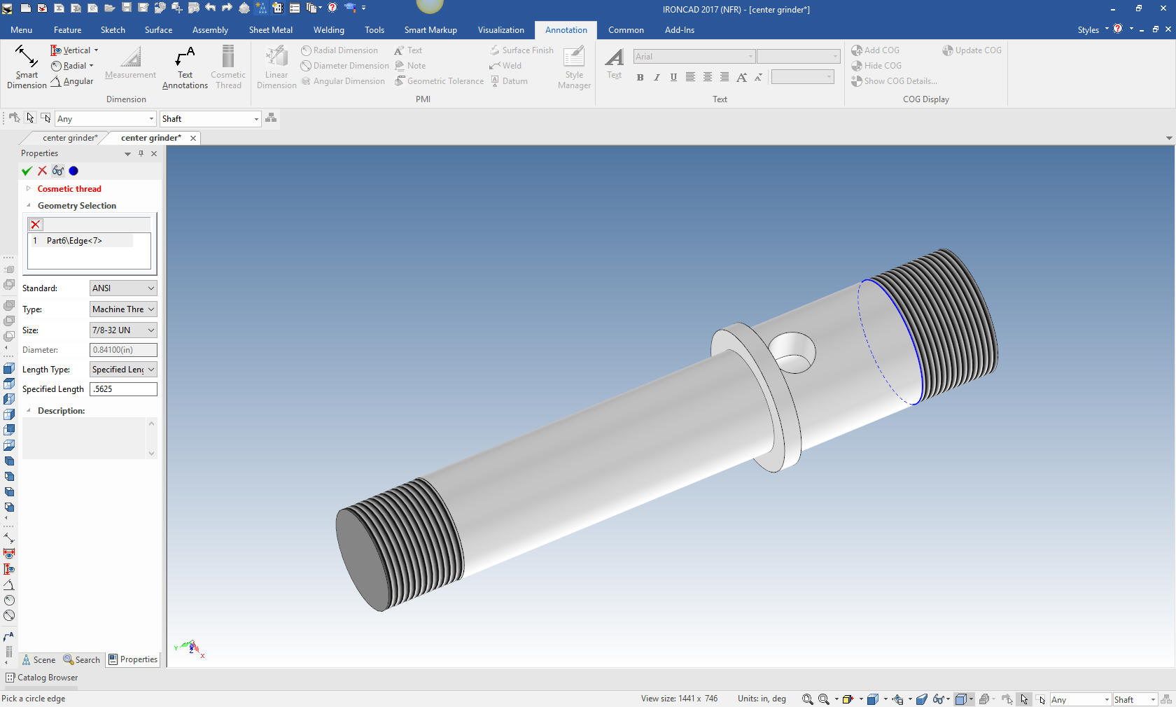
We now create the threads. These are
cosmetic threads and are recognized in the drawing.
We
will model the screw. There are two of these screws used. I am
assuming this would serves as a locking device for the bushing and a
lubricating hole.
We will drag an existing fastener from the
tools>fastener catalog onto the location of the screw.
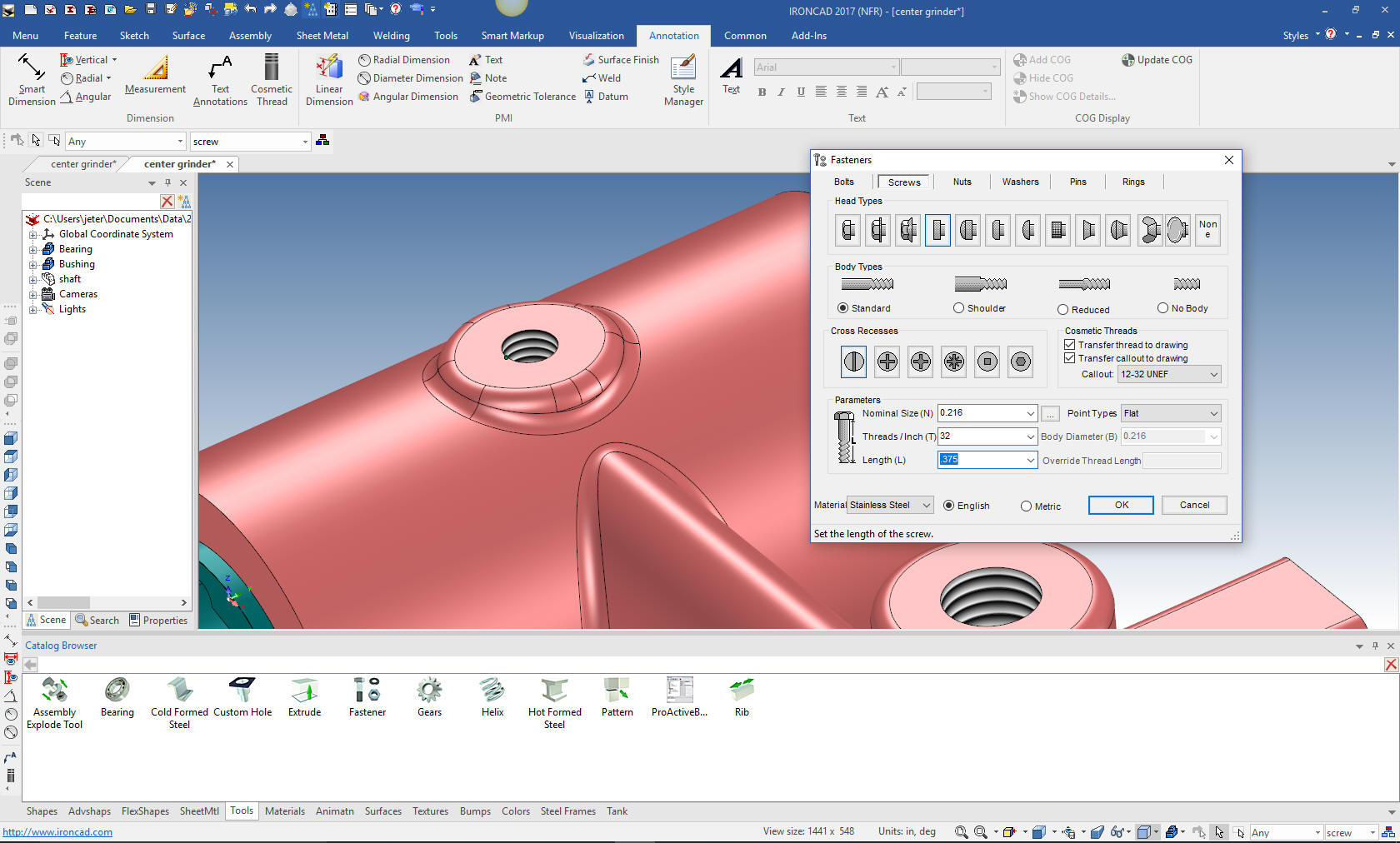
We now
are going to modify the exisiting screw. Like I said I am going to modify
it to meet the requirements I deem necessary. I like doing this as
I discover the problems to show we are not just a canned
presentation.
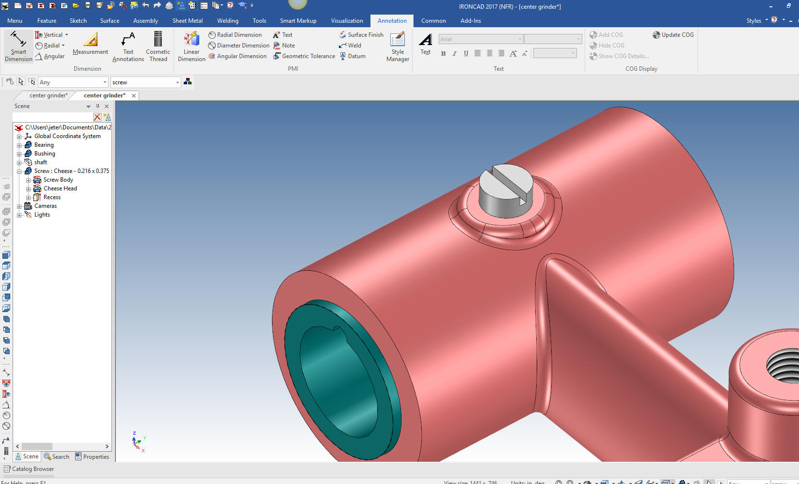
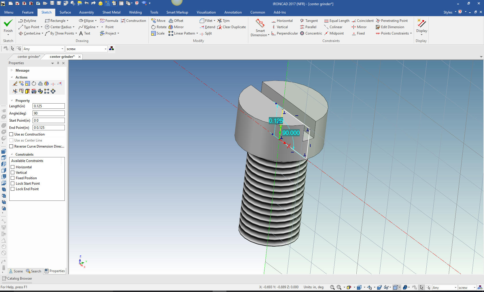
I hide
the Bushing and Bearing to work on the screw. I will first modify
the head. I will leave it the same height. Notice that the screws is
made up of editable sketches.
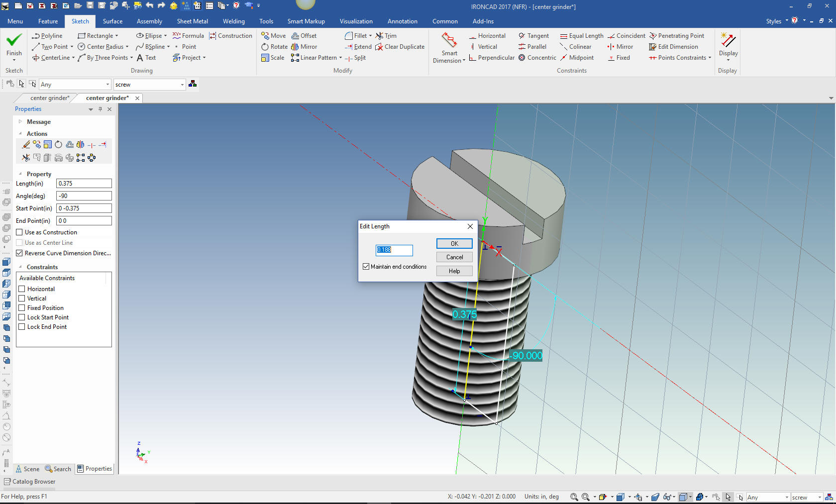
Now we
adjust the body. The fastener creation would only allow me to create
a body the same length as the diameter of the screw so we have to
modify it. Again you can see the sketch that makes up the body. We
set it at 3/16.
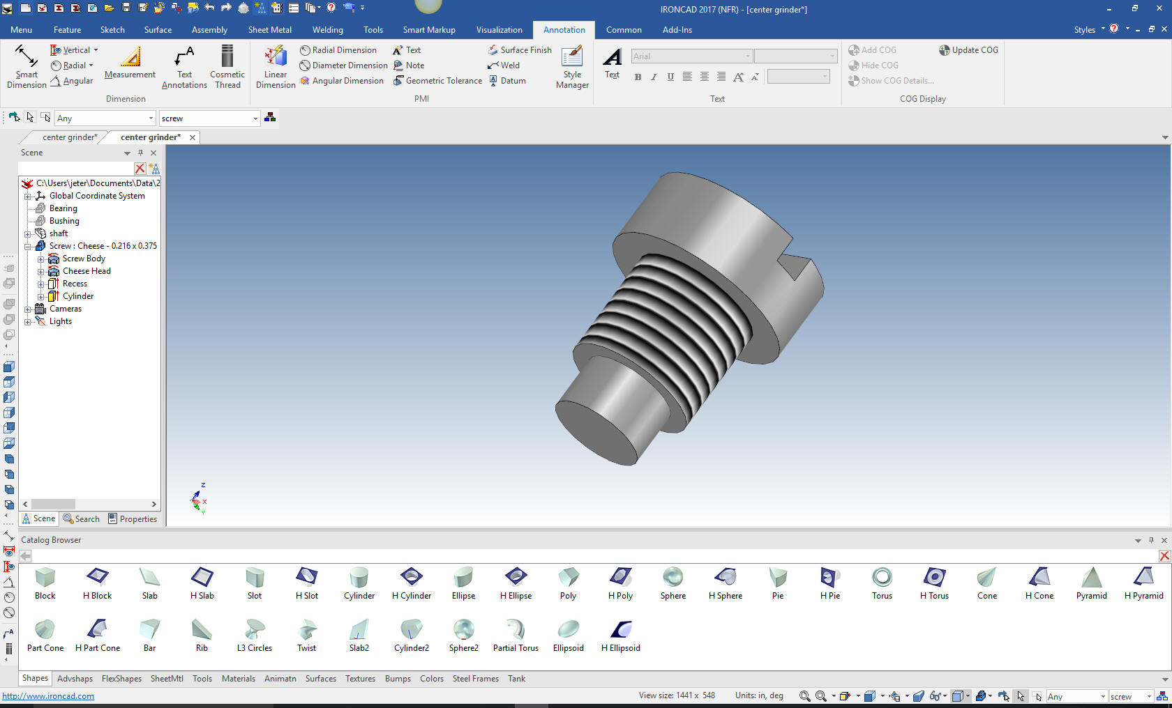
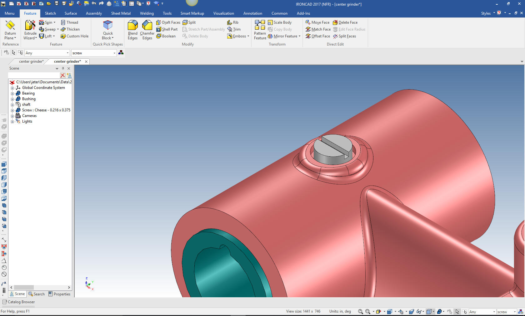
We add
the boss to the screw by dragging and dropping a cylinder to the
center on the bottom of the screw and sizing it. This is used two
places.
Now I
am going to create a counter bore of 1/16 make the screw effective
in locking the bushing. We will size it and move the screw into
place.
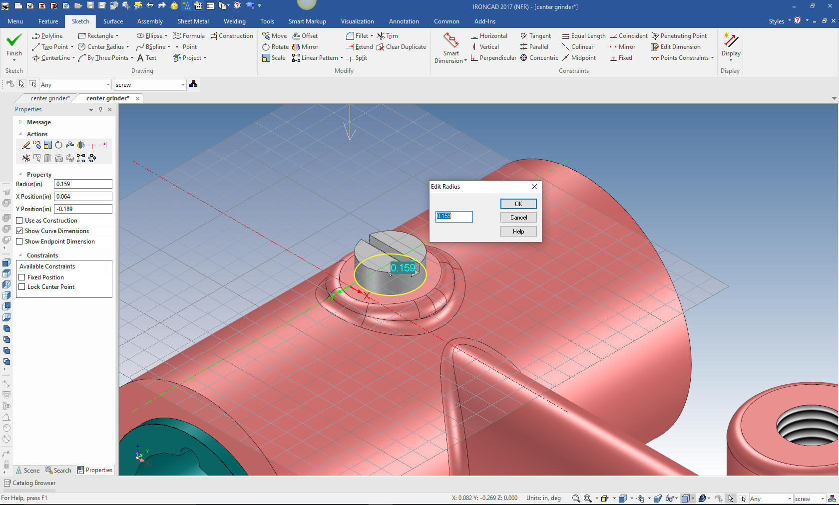
We move the screw to set in the counter bore.
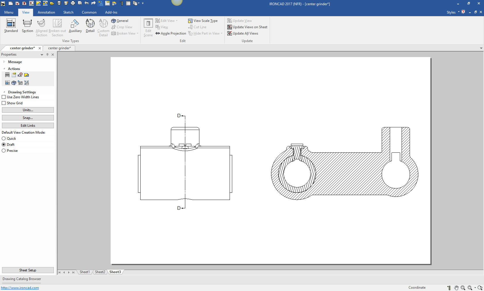
Since we have altered the design a bit, I do a quick section
view to see if there are any problems. You can see the drawing is
just another tab.
Note: I find creating the document and the
views much more clear than doing a section cut in the model. It also
creates a development path for others to have as reference if you
happen leave the job in the middle.
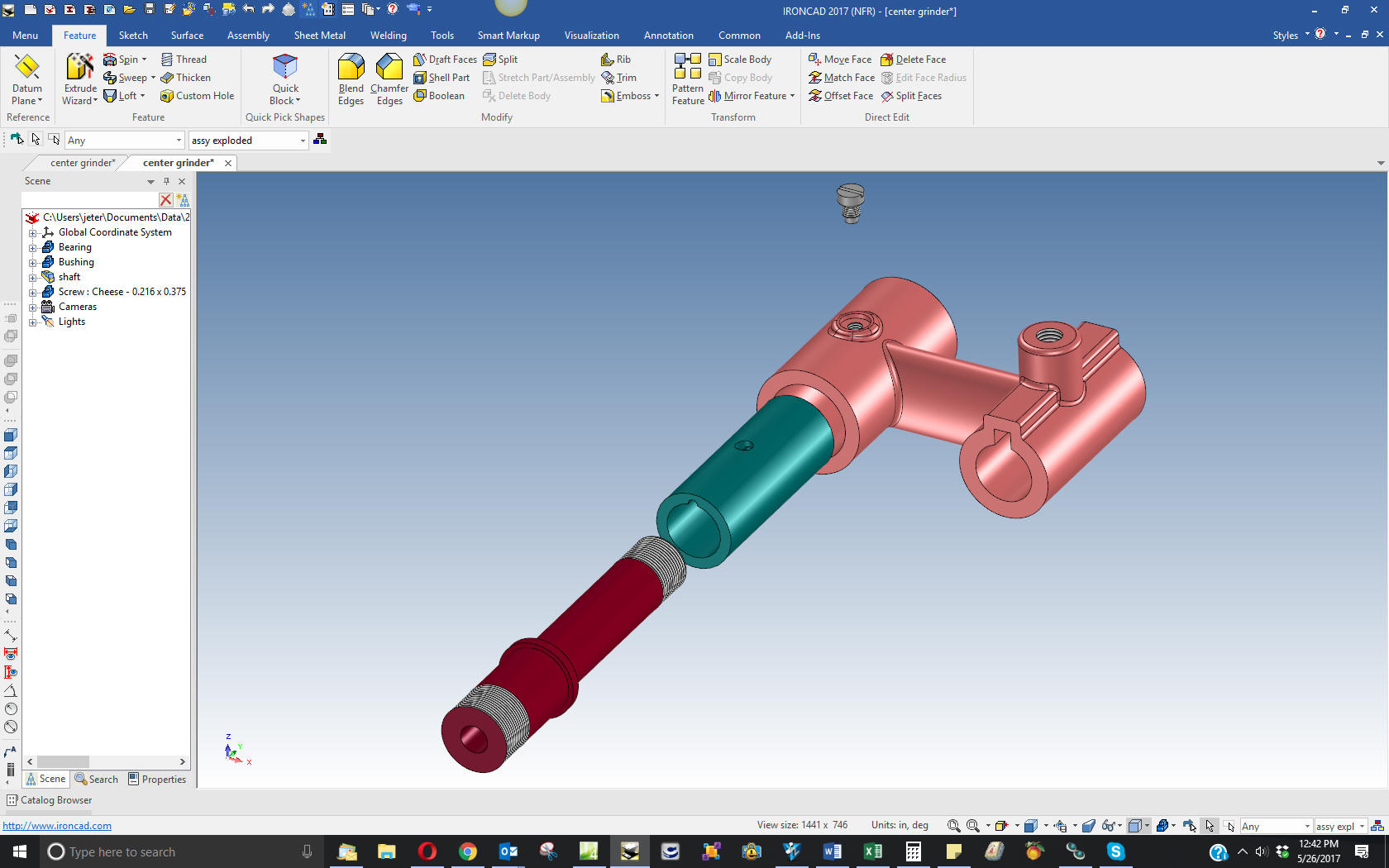
Here
are the parts we did in an exploded view. IronCAD allows you to
create an exploded view that does not affect the original location
of the parts.
I am
going to detail these parts in one sheet. Ironcad allows all of the
parts to be detailed in one document. Great for one person doing an
assembly.
For
those of you that are creating this parts you can go back to this
article. I have modified the Bushing drawing to reflect the changed
we did here.
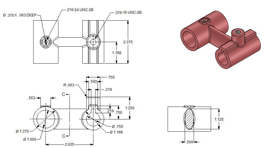
Here
is the original. I did add some dims that were not defined.
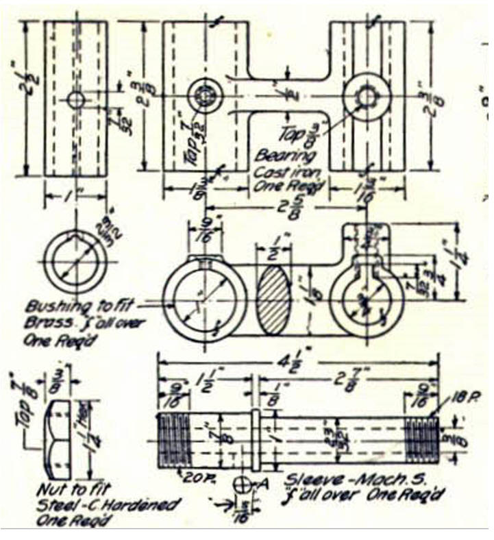
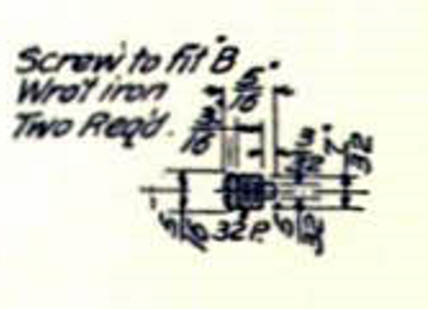
I did
modify the screw. You can imagine that this designer was available to
manufacturing to answer any questions.
If you would like
to try IronCAD, please download for a 30 day evaluation.
For more information or to download IronCAD
Give me a call if you have any
questions. I can set up a skype or go to meeting to show this part
or answer any of your questions on the operation of IronCAD. It
truly is the very best conceptual 3D CAD system.
TECH-NET Engineering Services!
We sell and
support IronCAD and ZW3D Products and
provide engineering
services throughout the USA and Canada!
Why TECH-NET Sells IronCAD and ZW3D
If you are interested in adding professional
hybrid modeling capabilities or looking for a new solution to
increase your productivity, take some time to download a fully
functional 30 day evaluation and play with these packages. Feel free
to give me a call if you have any questions or would like an on-line
presentation.
|