|
Can the 3D Model Be Used as the Design Authority?
|
|
Preface: Why are we trying to make the 3D model the sole design authority? What if we had the drawing included in the part file would this even be a consideration? Of course, not, I have had the drawing included in
the part file since the beginning with PC base 3D CADKEY in 1989. Even
AutoCAD had Paper space. There are four programs that have the drawing in
the same part file. They all can have the part/assembly/drawing in the same
file. We represent ZW3D, which is the only one of the three that offers both
history and direct edit modeling and all offer the single model environment. When PTC release Pro/e and made the drawing a separate file they did not know the problem that they would have with PLM and PDM? No! At the release of Pro/e we were still delivering drawings as prints. All document management was inside the CAD system. The engineering deliverable was the model in the form of an IGES file and the print. No, they would not send the native files. They knew at that time the "drawing" had to be "in stone" and delivering as a print was the only solution. The model had the same problem and IGES was the "in stone" 3D deliverable. Some where between releasing the prints and the entry of the PDF came the MBE and the silly PMI (Which I will get into later). If the PDF was released earlier, we would now be releasing the Print as a PDF. Which most of the smaller companies are successfully doing today. Sadly, all the popular programs have copied this
limited paradigm. Just think if Catia would have looked around at the other
programs available and saw the advantage of the integrated drawing. There
would be no need to have We would release our engineering as a model and a
PDF, by now we would have a special STEP format that could include both the
native file with the drawing as a PDF plus a step file. All would be right
with the world. Now the drawing could be at any level of detail, from
completely detailed, partially detailed or minimized GD&T. MBE is just another band-aid for ineffective document control. I have written many
articles on why PLM and MBE will fail but never answered this question. PLM has attempted to manage a company’s engineering
system, thereby affecting much of the company’s departments and
functionality. These PLM systems are based on the company CAD system. I will focus on Boeing since it has been leading
this effort since the release of Catia 5 and I have been directly with
the effects it had on the suppliers. I became a 3D CAD designer in 1982 on Computervision CADDS 4 then in 1986 I was introduced to PC based 3D CADKEY while on contract with Boeing Flight Deck in Everett. They were using Catia 3 at the time. All 3 systems were 3D wireframe design. Both CADDS 4 and Catia were well over $100,000 per seat. CADKEY with a 386 computer and a 19-inch color monitor went for about $10, 000. The PC could also be used for all the other purposes of a PC. I saw the writing on the wall and became a CADKEY dealer in 1987. The Worst to Best 3D CAD System and Why
Wireframe design was the only system available into the 1990’s. The only
product was the detailed print. Which did not alter the drawing as the
authority standard. But things started to change in the early 1990 with
the introduction of surfaces. CNC was now able to use the surfaces in 3
Axis programing. We did have a bit of 2.5 Axis with wireframe. But this
opened the door to the 3D model used as a pattern. Solid modeling hit
the PC in 1995 with the introduction of the Parasolid and ACIS solid
modeling kernels. CADKEY, Solidworks, IronCAD (as Trispectives) and a
variety of other programs were released. We were now delivering the 3D
model along with the paper print to the suppliers. The PDF showed up at the end of the 1990’s as a
viable replacement for the paper print. We were then delivering the 3D
model in the native or neutral format and the detail document as a PDF
as a zip or in an email. But something else happened in the late 1990’s. The
high-end systems moved to the PC. Prior to this all the Boeing suppliers
in the NW were using CADKEY. It was the only viable 3D package to
communicate with Catia 4 which was still out of the reach for the
suppliers. The move from Catia 4 to 5 was a fiasco that I can not ignore in this article. Catia 5 could not directly read. Even if they imported the Catia 5 history based only design system could barely use them. CADKEY soon added the ability to import and export both Catia 4 and 5. It was soon used by Boeing Commercial to move Catia 5 files to Catia 4. It was not a straight conversion. Catia 4 could only read a 34 meg file. So all of the models had to be broken in to smaller files. Boeing would have never done the following if they would have based their engineering on the flexible PC based 3D CADKEY!! Enter the 3D Model as the Sole design Authority They moved to the PMI
(Part Manufacturing Information)
I started getting calls from my customer telling me
that Boeing was not sending prints. They didn’t know what to do. Boeing changed the complete engineering deliverable
without informing the suppliers!! The suppliers were scrambling, many were buying
Catia 5 seats to be compatible. They had to at least a seat of Enovia to
view the PMI. They were demanding STEP or IGES files as before. If I
remember Boeing seemed to keep supporting that. Many tried to work
around this situation trying to avoid the added costs. The suppliers were still using the much more user
friendly CADKEY. CADKEY soon added the capability of importing native
Catia 5 files. This solved much of the problem. But still had to view
the PMI information for tolerancing for inspection. But soon the suppliers were complaining about
corrupt Catia 5 files. Catia 5 produces more corrupt files than any of
the other CAD systems.
Boeing solved this by recommending Validation
software. This would compare the original Catia 5 file to the file that
would go into the CNC. Step or IGES. This would create an 8.5 x 11
report that had to be saved just in case Boeing would come by for
inspection. They never have inspected any of the suppliers. This 3rd
party software is now required. This just some kind of process that
makes someone feel good. Like comparing apples to apples. This is just one of the many band-aids that Boeing
has added to this failed process.
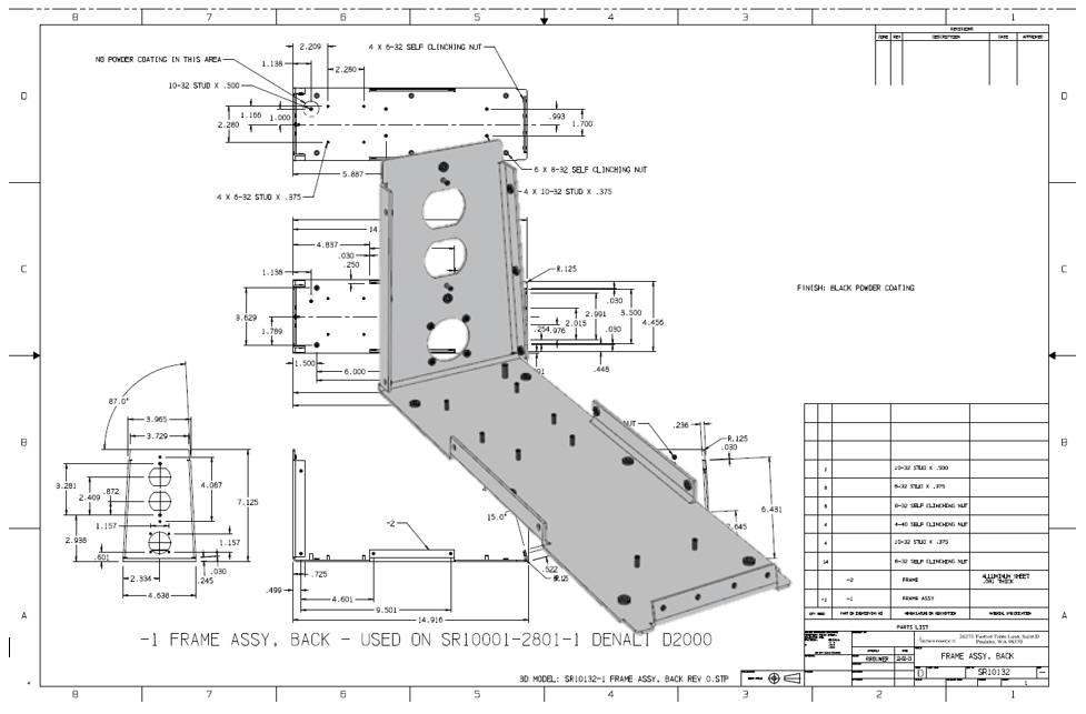
Why did they move to MBE? Let’s look at what this is replacing. The Standard Drawing. This was one single document that completely
defined the part. That is all the description necessary. So why didn’t Boeing keep the drawing?
Of course, we didn’t create drawings anymore. We created what Boeing called the “Flat File”
which I have coined the AID (Associated Information Document). These
were documents created in the Documentation module as a separate file in
Catia and all the Pro/e clones. These were very simple to create. Just
attach the dimension to generated views associated to the 3D model. We
were using and still are using the same format as the “Standard Drawing”
which confused many that started calling these “2D drawings”. A silly
redundant moniker that is now standardly used by virtually everyone. With the introduction of the PDF why didn’t
Boeing use the AID for definition and the 3D model as the pattern? That what was being used with all the other
mid-range systems, CADKEY, IronCAD, Solidwork, Solid Edge, Inventor etc. This PMI concept came out before the PDF was widely
in use. Remember they were trying to eliminate the “PRINT”, they were
now stuck with the process after all the investment and the promise from
Dassault that Catia 5 could handle all the “data management” of
engineering documentation.
Sadly, “Data” is an InfoTech word that does not
correctly represent the product of engineering that is “Documents”. The was called “Document Control’ that handled the
single document “The Drawing” But IntoTech or BCS and Dassault with Catia 5 was
now in charge of Boeing engineering and the focus quickly move to “Data
Management” not the engineering. I believe that these folks never even
looked at the existing “Document Control’ system. The Document Control Group The Document Control group was eliminated at Boeing with the entry of Catia 5 PLM. It was made up of admin people that would take the engineering deliverable at the time, which consisted of only the drawing. They would record it and create the blueprint, distribute and put the original drawing in the vault.So, MBE was put in place Many others thought this was a viable process. The
government got involved. Mostly basing the process on small engineering
projects where everything could be controlled. Never really
understanding that this also had to be coordinated with outside
suppliers that did not use the same software. The true culprit here is the PMI. Today, 20 years after Boeing has had this system in
place and all the major programs have started providing PMI
functionality there is no standard importer. I call it an importer not a
reader because the 3D model is part of this format. There are a few importers that are available. ZW3D
can import them. But the problem is that each CAD system is in a
different level of release. PMI is system sensitive. There seems to be a STEP format that they can save
the PMI, but that is another step (no pun intended). But that does not
meet the Boeing standard of the native file still be required. You must
read the Boeing native PMI to be compatible. If you use anything else,
you must have a validation program even if you have a seat of Catia 5. Nobody is thinking this through. The 3D model but it
cannot stand alone. It truly is only a pattern that drives CNC if it is
a machined or sheet metal part. PMI completely falls apart if it is a
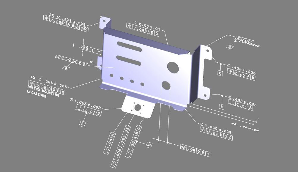
weldment, sheet metal enclosure or other inseparable assembly. Today the PMI consists of a minimizing of GD&T
symbols. The parts they use as examples are not complex. I have seen
section views which defeat the purpose. So why if PMI is such a marginal deliverable as
compared to a completely detailed AID. Why do they insist on this
format? I thought you would never ask. I all has to do with data management!! Ah, that ‘Data” word. PLM is based on a Pro/e 3D CAD systems paradigm.
All the larger companies have based their engineering on Catia 5, NX or
Creo. These systems have separate parts, assemblies and
AID (drawing) files. These ‘drawings” are associated to the part file. This is a horror show for data management. These two files must go together. These people “think” the deliverable must be the native files. They don’t realize that the engineering deliverable should be files that are not dependent on the 3D CAD system. It should be the 3D model and the AID (drawing) delivered as a PDF. Moving the document control out of the 3D CAD system, which is a poor delivery system forcing those that are interested In the documentation having the system or compatible view. The only reason for this is that the CAD company wants more dependence on their products. This should be a big “DUH” moment for upper
management. Most just ignorantly have Dassault, PTC and Siemens hands in
their pockets. Don’t think the midrange programs such as Solidworks,
Inventor and Solid Edge have missed this. This process can produce
millions in profit for these companies. The Fox in charge of the Hen house? Of course, this
is so blatantly obvious that I figure management in the large companies
are getting kickbacks. So Joe, you haven’t proved a thing!! This is a
cost-effective process!! Proof you want? There are 3 systems that have the part and AID
(drawing) in the same file. Would you think for one moment that PMI would be
developed if the AID (drawing) was in the same file? OF COURSE, NOT!!! So, this complete process is so they can use the
dated Pro/e clone technology. No one even knows this. No one even
investigated it. Boeing when they had Pro/e envy in the mid 1990’s
didn’t even look around to see if there are any other more productive
systems. Even though they were using CADKEY, one of those systems. I
have never seen such lack of innovation in the development of any
technology. Even today, Onshape, developed by the founder of
Solidworks added very little CAD design innovation. Even though I gave
them a presentation of the most productive 3D CAD system, IronCAD. I
could only surmise it was to capture the interest of the existing
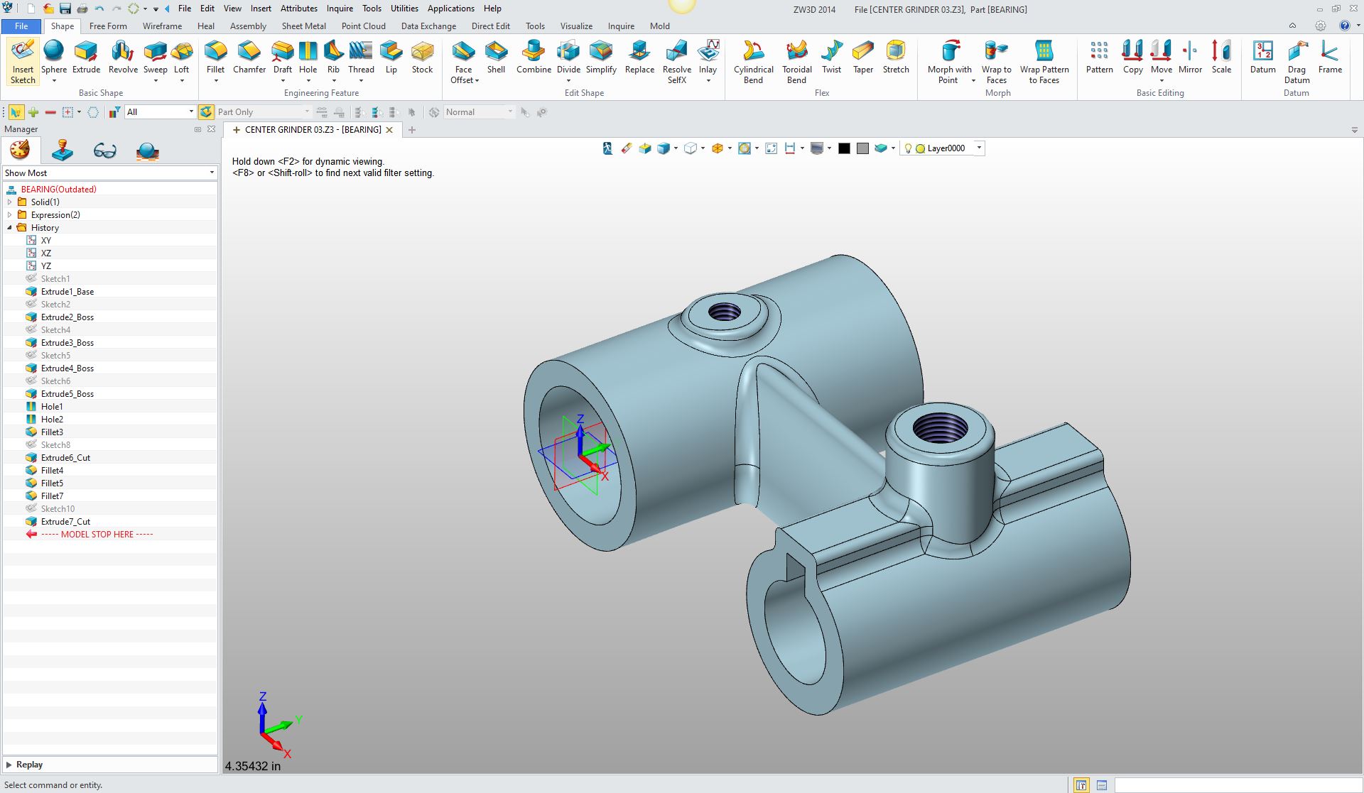
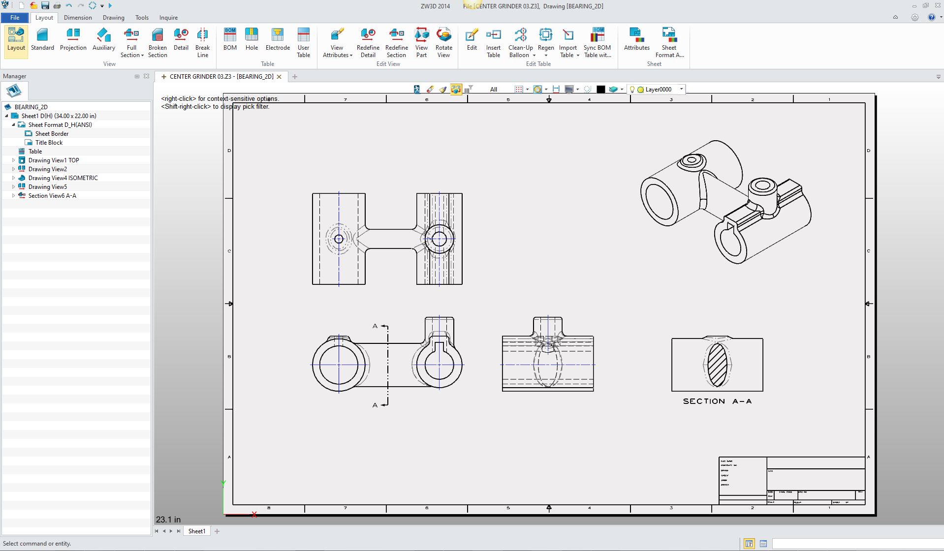
Solidworks users. Here is an example of a program with integrated
drawings.
Here is the AID (drawing) in the same file. What PDM miracle!
But as we come to the end. Only those that have no
understanding that the 3D model is nothing but a pattern see it as
something that can be used as an authority. There are other problems with using the 3D model as
the authority. If you have a change everything stops until that model is
rereleased. This could take a month. Remember they used to trust
manufacturing to create the parts from drawings. But the 3D model is
sacrosanct. That is the problem. With an AID (drawing) you can have two
documents that can be used for inspection and comparison. If there is a
small change you can send out an updated PDF and the supplier can make
the change. This is the problem with the history only based
3D CAD system.
Yes, much of this would have to be worked out but
from a much more flexible and usable basis. Two associated documents,
the 3D model and a completely detailed document keeps our old friend
Murphy at bay. We would have to move to more flexible hybrid 3D
CAD modeling systems and a standard and certified neutral format that
each CAD system would have to meet. To get any change we are up against some powerful
foes.
So, there you go You can now answer the question. Can the 3D Model be effectively used as the Design Authority? If you are in a management of academic position and you would like to explore other related CAD subjects please feel free peruse some of my other related articles. Viewpoints on the 3D CAD Industry
TECH-NET Engineering Services! If you are interested in adding professional hybrid modeling capabilities or looking for a new solution to increase your productivity, take some time to download a fully functional 30 day evaluation and play with these packages. Feel free to give me a call if you have any questions or would like an on-line presentation. |
TECH-NET ASSOCIATES | RENDERING OF THE MONTH | CAD•CAM SERVICES
HARDWARE | TECH TIPS | EMPLOYMENT | CONTACT