|
Reference Articles:
“Redefining 2D/3D”
"The Embedded
Title Block!
A PLM Solution!"
"The Worst to
Best CAD System and Why!"
"The Death of the Drawing"
The 3D MCAD MODEL?
COMPARE AND VALIDATION PROGRAMS?
BAND-AIDS FOR SELF INFLICTED WOUNDS!!
Apples to Apples?

VALIDATION PROGRAMS
3D CAD model validation software is probably a bit foreign to you. Only the larger manufacturing companies that have based the authority of their engineering documentation on the 3D model have required their suppliers purchase it. Most smaller companies have stayed with conventional documentation which includes the 3D model and the fully detailed AID (Associated Information Document (drawing)). This is one of the unintended consequences of the MBE (Model Based Enterprise) and throws the engineering documentation to manufacturing process into a tizzy.
Validation programs were released a few years ago. They were created to compare solid models to make sure what the supplier was machining was what the customer sent. They program cost over $7,000.00 and produced an 8.5 x 11 "PIECE OF PAPER" that said it was a good part. Which a Boeing supplier would stick in a file. Now you would think the actual inspection of the finished part would be the final validation. But no, Boeing demanded the supplier to assure the solid model was just like the solid model they sent. Apples to Apples??? Of course.
Can the 3D Model Be Used as the Design Authority?
I have been translating parts between systems since 1986 while at Boeing, I transferred files between CADKEY and Catia 2 using IGES. With the entry of solid modeling, Boeing has put in a requirement that the parts must be validated. The reason is that Catia 5 translation cannot be trusted. Catia 5 can basically only output STEP. The problem is not with the receiving CAD product but with Catia 5. Catia 5 produces some of the most corrupt parts I have ever seen. Yes I have also seen corrupt parts from Pro/e and Solidworks but not at the level of Catia. I believe it is the Pro/E paradigm of history based solid modeling that allows this corruption, trying to create parts that are beyond the products limits. Many CAD products directly read native Catia 5 file, yet Boeing does not even trust these translations.
Corrupt 3D CAD Parts
Talking to Catia! and other Popular 3D CAD Packages
Is 3D CAD Productivity an Oxymoron?
COMPARE PROGRAMS
The Validation programs would also find differences in the different revisions of the part. But at $7000.00 it was a bit expensive. Now comes a COMPARE program. This was a cheaper version of the VALIDATION program that would only show the differences in the part.
WHY WOULD WE NEED PROGRAMS LIKE THESE??
You may not be old enough to have ever made or even seen a complete drawing. Drawings were documents that completely defined the part with separate unassociated orthographically projected views. Notice I didn’t say 3D part because that would be silly. Of course there are no such thing as 2D parts.
Please read my articles
"To Draw or Not to Draw?" and “Redefining 2D/3D”.
These drawings not only defined the shape of the parts but they also gave all the information necessary to create these parts, material, tolerance, finish, etc. All the pertinent information in one place also for inspection. There was also a very complete revision system. Each DCN (Drawing Change Notice) noted all the change history of the part. An ADCN (Advanced Drawing Change Notice) was a description of the change done on 8.5 x 11 sheets of paper so as to not require the amount of time to directly change the drawing every time a small change was made. These were simply stapled to the blue print (a print of the drawing). When a few of these accumulated they would be incorporated into the original drawing as a DCN and a new revision letter would be assigned.
The ADCN (Advanced Drawing Change Notice) vs MBE (Model Based Enterprise)
Can you imagine doing a change to the drawing and not defining it?? Just sending out the drawing with a different date and name. No, of course not, that would be insane. Let’s say you changed a hole size and the drawing had hundreds of holes, you would have to look over the complete drawing comparing it to the old drawing. That is what the necessity of a Model Compare Program is indicating that is happening in the industry. It is data out of control.
Enter Solid Modeling
Today the engineering industry is trying to eliminate drawings. We can now directly give manufacturing a solid model of the part. They can now take the solid and create tool paths to drive a CNC mill. Absolutely wonderful. But we still have to qualify the features that mate with other parts. We have to inspect the parts and the CNC programmer and machine operator may have to put more attention on what is important when programming the code. So there is still some tolerances or GD&T data required.
Now the part is programmed and the parts are made. Now comes the revision. What do the manufacturers send the supplier? Now that the solid model is the authorizing document, they send a new solid model. Is there a description of the change?? Well obviously not. They do have a format call PMI (Part Manufacturing Information) which has a bastardized form of minimized GD&T dimensions and annotation in 3D space (see PMI vs AID). I am not sure it even has the capability of describing the change. But it requires the native software or a 3rd party program that reads this data. But many of the companies are not getting this data and are only receiving a STEP file with a name. Now the file name probably includes the revision letter. So you now need a program to compare the parts. Why? So you can see the difference and be able to utilize the original complex CNC program so you don’t have to reprogram the complete part.
Why MBE/MBD/PMI Will FAIL
Why MBE/MBD/PMI Will Fail Part II
Free PMI Importer?
PMI vs AID (Associated Information Document)
What does this tell us. The originating company does not have an effective way to communicate the changes. Imagine spending virtually millions of dollars on a CAD system, and it does not have the capability to document the revisions of the part to an outside supplier. Each of the large systems like Pro/E, Catia and NX have and brag about their PLM (Part Lifecycle Management). There are even 3rd party PLM programs to make matters worse. There is a huge vested interest to keep this non-standardized. This is costing companies like Boeing millions of dollars in scrapped parts and missed schedules.
Don't believe me!! Here are 105 programs that claim
to be PLM.
Product Lifecycle Management Software
Solutions
1. Have all of your suppliers on the native system.
But what small supplier can afford all of the high end systems? Not only is the cost prohibitive, but all of these systems are complex and require huge learning curves, demanding an expert user on staff.
2. Use the Validation or Compare program.
So you spend extra money to buy a program that is nothing but a Band-Aid to fill a gap the customers software does not supply. Opening doors to errors by not having a direct communication with the client.
3. Just ignore it and build the parts.
This is the solution many of my customers have used. Just treat the revised part as a new part and charge accordingly adding thousand$ to the price of the parts.
4. Do all your manufacturing in house.
I am not even sure this solution works without a lot of support.
True Solution – A New Standard
So what do we do the fix this problem? We have to devise a new system that supplies the necessary information we had with the drawing.
1. First is to assure the supplier he has latest revised part.
This is very easy and I am very surprised it has not been thought of.
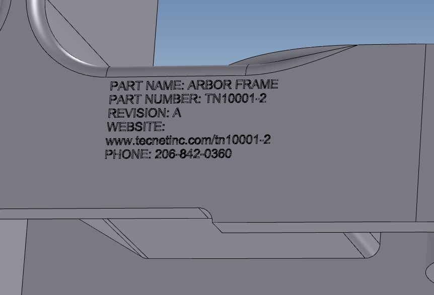
The Embedded Title Block!. Most CAD programs can create 3D text. You just put all the pertinent information on the part itself. This can be embossed, embedded or even added as a tab. All CAD programs can fill it in or subtract it from the face. This text would indicate the part name, number, revision, information webpage and contact info. By making the text part of the part, it allows programs that have a separate part and assembly format to read the part without making the text a separate part and thereby creating an assembly.
2. Available Webpage.
We would create a webpage for every part. On this page would be all the information on this part. Latest revisions that can be shown on a drawing and even a 3D representation. This webpage would allows downloading of part in different formats such as STEP, IGES, ACIS, Parasolid or the native file.
The Ultimate Engineering Document Control System
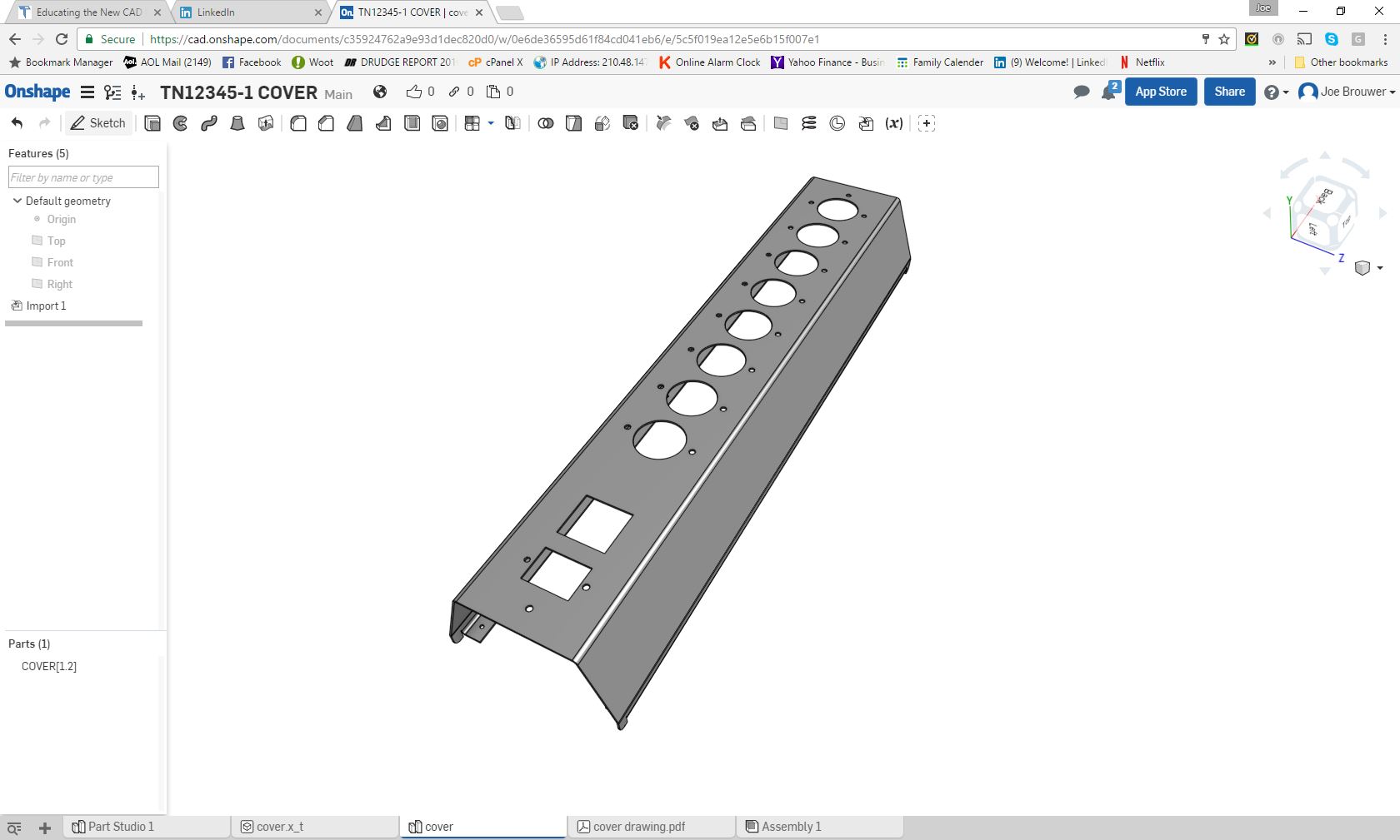
Onshape now offers the above solution:
OnShape: The Ultimate Document Control System
GrabCAB Workbench can be used today for a free Cloud/Local based Document Control System for smaller compani es. The larger companies would have to look at a modified OnShape or another firm to develop a effective cloud based system. If there is a company out there that would like to provide this incredibly effective standardize system give me a call.
Joe Brouwer 206-842-0360
Standard
Cloud Based Engineering Document
Control
Standard Cloud Based Engineering Document Control Part II
"The Embedded
Title Block!
A PLM Solution!"
"Onshape! A View from the Clouds"
Now this would eliminate the need for all of this PLM baloney or at least give PLM stable engineering documentation. It would be available to all the divisions in the company and authorized suppliers. It would require no unique software. This could be controlled by each group. Much of it would automatic. A notice could be sent out instantly when a changes is made or a part would be put on hold.
Imagine a liaison engineer finding a problem with a part on the manufacturing floor. He could actually create a rejection tag and notify the responsible group instantly just by having access to the webpage. Then with a quick look the group could put the part on hold, if required, while the change was made. The supplier could be instantly notified and stop work on the current parts thereby reducing scraped parts.
This is not CAD specific. You can use virtually any CAD system you want. The groups would create AIDs or drawings that would be in a PDF format on the webpage. The changes could be presented in a small view only describing the change, there by not requiring a complete revision of the drawing unless the change was extensive. I would suggest complete standard drawings since that leads to a better understanding of the part for the original designer. But even if it was only the GD&T data in a drawing format would be huge to eliminate any miscommunication.
I have come to the conclusion that MBE will not work and we need
to go to the AID (drawing) as the authorizing document
and the model as nothing but a pattern if it is necessary!
Please visit my article “The Embedded
Title Block!
A PLM Solution!" for a more detail description of this concept.
PLM soon will be taken out of the hands of engineering and placed in the appropriate division “Document Control”. Soon it will not matter what CAD system you use. So why would you struggle with complexity when there is a much easier and productive CAD package available.
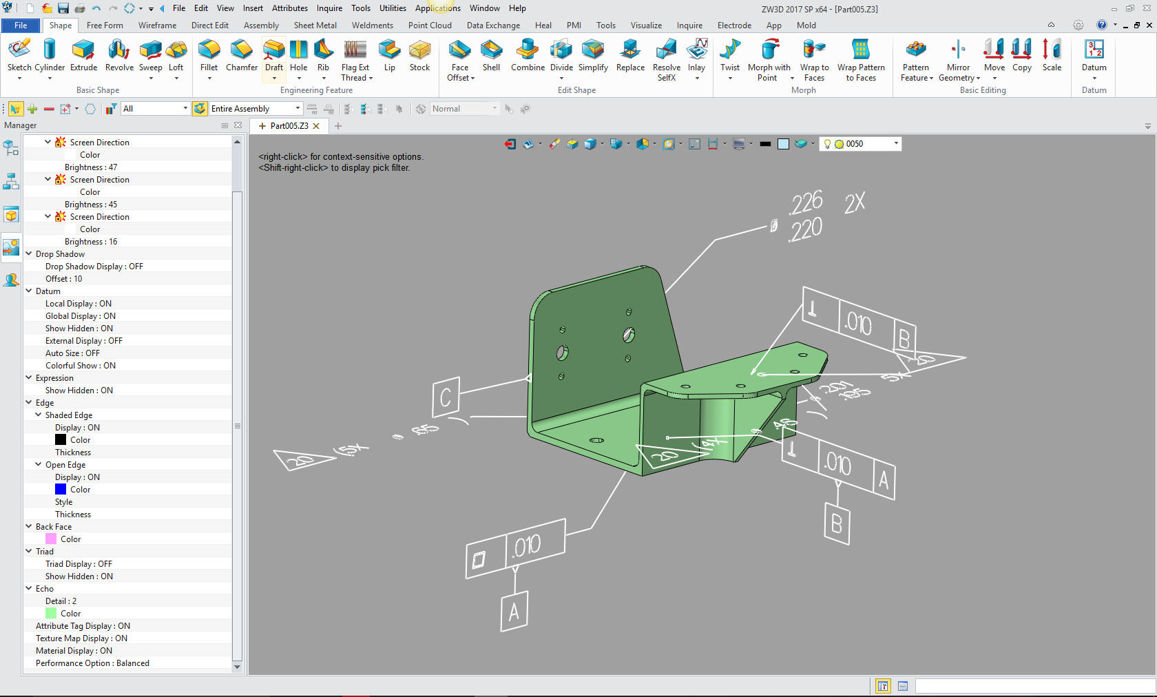
If your CAD product does not have the ability to create 3D solid text please take a look at IronCAD/ Inovate or ZW3D. Yes there is an alternative to the dated Pro/E (Solidworks) MCAD system paradigm. A program that has both the Parametric History/Feature and Direct Edit Based Solid Modeling integrated into one system. Programs that are much easier to use. As the industry slowly moves toward a standard we will always want the quickest and simplest way to do our design, IronCAD/Inovate and ZW3D offers that alternative solution at a very cost effective price.
You are Not Stuck with Autodesk, PTC or Siemens Subscriptions!
TECH-NET Engineering Services!
We sell and support IronCAD
and ZW3D Products and
provide
engineering services throughout the USA and Canada!
Why TECH-NET Sells IronCAD and ZW3D
If you are interested in adding professional hybrid modeling capabilities or looking for a new solution to increase your productivity, take some time to download a fully functional 30 day evaluation and play with these packages. Feel free to give me a call if you have any questions or would like an on-line presentation.
|