|
WHY MBE/MBD/PMI WILL FAIL Why is it those that promote MBE never use it? |
 "Engineering's only purpose is to deliver complete, concise and unambiguous documentation to manufacturing." I am sorry I am so blunt in these articles. But if you see the amount of waste that it is causing in errors, slipped schedules, collaboration, document access, revisions and more as compared to, what I consider now, the more productive process when it was based on paper drawings. I mean the only thing we added was the 3D model. So what "HAS" gone wrong with Engineering? Part II I received an actual released PMI from a large Aircraft manufacturer. This shows how convoluted and non-standard the PMI really is as a engineering deliverable. I have done a comparison with a fully detailed AID (drawing) see the incredible difference in information. The AID (Associated Information Document) travels with the 3D model is a reference document that also aids as a check for the designer on his design and an easily reviewable document. Only those without any engineering documentation experience could possibly think this could replace a completely detailed AID for concise, complete, unambiguous information and an easily viewable document. I will send anyone interested this Catia 5 based PMI. If you can even read it! Why MBE/MBD/PMI Will FAIL Part II PMI vs AID (Associated Information Document) Here is my latest companion articles:
Can the 3D Model Be Used as the Design Authority?
New
Sorry about all of the updates. I will incorporate with the next post. Update 7-9-18 It just gets worse! This process is impossible to Standardize! Here is an industry report that shows that MBD is failing in so many ways. Minimum Model-Based Definition (MBD) and Bill of Material (BOM) Definition with STEP AP242 The first mistake is trying to create a neutral STEP format. Adobe Acrobat 3D was released in 2007, could read the native Catia 5 file with PMI and deliver a Step file. As we were ready to present it to Boeing it was sold to another company. Why? Dassault was making sure that MBD was in place and only the Catia 5 native file could be used, requiring a seat of Catia 5 or Enovia. Yes, Dassault was and still is in charge of Boeing's engineering process. Boeing MBD rule #1: "The Native 3D Model is Sacrosanct" No STEP file will do! While we do need external engineering documentation the PMI in a STEP format is worthless, for so many reasons as I describe below. I will be taking this report apart, piece by piece. It is so simple. Not one person involved with this report has any applicable engineering experience. Luckily, the smaller companies are not driven by the major CAD vendors. They should be looked to, to solve our engineering documentation problems. The problem with this report is it gives the companies the idea that they are in charge of their engineering process. Dassault, PTC and Siemens and the PLM and InfoTech gurus run the show. The costs are enormous! It was more cost effective when the engineering was based on the "manual" drawing. All we did was add the 3D model. BOM?? Only a Millennial Engineer would even use this term. Update 10-23-17 Look at this idiotic graphic. It is done by genius PLM Gurus that have no applicable experience in engineering proper. Look at some of the titles.
Engineering Documentation - A Primer for the PLM Guru! The biggest joke is DFM (Design for Manufacturing). If you are a designer, what else would you design for? What is coming out of engineering that requires someone to ask this question? Model based design is no different than design with a drawing! Sadly, not one of these PLM gurus can even understand the drawing. The drawing is a 3D model to those that can see it in 3D. The 3D model is nothing but a digital pattern. You can not run engineering or a corporation with a PLM system. Why? There are 4 basic "separate groups" in the past engineering/manufacturing process. Each one has a specific purpose based on a standard and run by those that have expertise in these areas. You have to develop a standard engineering document that can be easily utilized by each group and other interested parties. In the past it was the "drawing", a single complete and unambiguous document stored as blueprints. And now we have the digital age (buzz word) to make it more efficient and productive? It hasn't and is costing the industry a fortune in errors, slipped schedules and a wide open door to Murphy to frolic.
Design Engineering Look at this silly mess. You would have to have a PHD to even understand it. Oh, that's right, it took a PHD to develop it.
It really still bugs me that they call the Parts List, a Bill of Materials. It truly shows a lack of any investigative interests of the PLM gurus of the past process. Of course, when the CAD world was based on a poorly designed architectural electronic drafting package (Autocad) what do you expect? Oleg Shilovitsky is one of the most vocal PLM gurus, makes this observation in this article: "PDT (Product Data Technology) Europe 2017: The culmination of complexity in PLM and next steps" "What is the implication for PLM? How to make a change in complex environment? This is a question asked by many people working on PLM technologies. Unfortunately, you cannot solve the problem created by PLM tools using PLM tools. It won't work. PLM paradigms is what need to be changed first. How to do so? My advise - go back to basics and re-build PLM bottom up from simple systems that work. Granularity and global web scale are two fundamental principles of new PLM paradigm and architecture. Web technologies, cloud, new data modeling, global approach, new business models - these are elements of new PLM architecture and re-imagining of PLM. Just my thoughts..." I have said the above in many different articles based on following the conversations of many PLM gurus and being a highly experienced design draftsman. Remember the drafting groups total responsibility was the creation, correctness, clarity, release and maintenance of the engineering documentation. Sadly, for years, an effective digital process has been basically in place in small companies that cannot afford the high end CAD systems and their PLM fraud. Actually, industrial/mechanical engineering is relatively easy to digitize and incredibly cost effective and simple. The Ultimate Engineering Document Control System
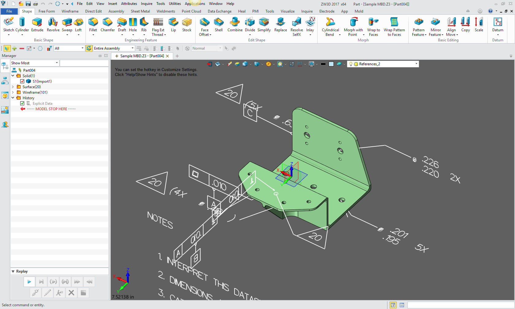
Update 9-28-16 Rarely do I update an article so quickly, but I just received a large aircraft manufacturers sample Catia 5 part with PMI from a prospect that is looking to ZW3D to import Catia 5 PMI native files. I couldn't believe all the text presented in a 3D space that was required to define the part. This was a very, very simple machined part. It has UOS (Unless Otherwise Specified) decimal sensitive tolerancing (.xx +/-.03 , .xxx +/- .010) yet there are no non-limited dimensions on the part. They have "notes" defining the tolerances for fillets, webs, corner radii, etc. It is a mess. They don't even have a title block with company information. No signatures in any of the information just the name of the designer. So there has to be another authorizing document. You can see the comparison to an AID (Associated Information Document) that travels with the 3D model and includes all of the pertinent information in a much more user friendly format.
This process is horribly expensive and time consuming! You need the native Catia 5 software at tens of thousands or an importer like ZW3D. No a free viewer is not viable, you need the model. This is all to replace an easy to create AID/Model engineering document that consists of the AID (Associated Information Document (drawing)) delivered as a PDF and the model as a STEP or even a native file. Catia 5 is the easiest 3D CAD system to replace, all systems can import and export Catia 5 files. Sadly, there is no one group or person that has the interest or power to even evaluated this process. This is a case if you follow the money it leads you to the pockets of Dassault, who are laughing all the way to the bank. Here is a comment from a MSME PE on this article when I posted to Linkedin. "The big problem is, any failure will be blamed on the responsible engineers and not an unworkable system. MBE is already being backstopped by drawings in many organizations that are forced to use MBE, but the drawings are frequently not in the release control process because they are not the "primary" data driving fabrication. A fine mess.." Trust me the smart engineers are creating AIDs (drawings)!
What is MBE/MBD/PMI MBE – Model Based Enterprise This nothing more than the implementation of the MBD MBD – Model Based
Definition This is where we add the important information to the
model creating an engineering deliverable that manufacturing uses to create the part. This serves the purpose of the drawing in the past and
should stand alone. PMI – Product and
Manufacturing Information This is the format that MBD delivers the engineering information.
"You cannot base your engineering The Three Current Engineering Deliverables 1. DRAWINGS This is a document that is made up
of separate non-associated orthographically projected views. These can
be created by manually drawing or by creating entities in an electronic
drafting system now synonymous with Autocad. Why do I say create entities? Because they are not really drawn are they? Even though we do not draw anymore they still qualify as drawings per the above definition. 2. AID (Associated Information Documents)/Model
Yes, this is something I have
coined. But the document we create today is not a "drawing". The AID is what most of us 3D CAD designers
use to for our Computer Generated Graphic Engineering Documents. But
these documents are much different than the electronic drawing systems.
With this we actually created instances of the model in an included
documentation module in the 3D CAD system.
Enter Model Based Definition. The PMI was not the first MBD format. Now at that time the 3D wireframe model was only use to create the AID. It wasn’t until years later when CNC was introduced that we included the model and paper print. 2.5 Axis CNC could utilize the 3D wireframe. In the late 1980s surfacing showed up and we were now providing surfaces for 3 Axis machining. Even though solids showed up with Pro/e in the late 1980s the normal format delivered to manufacturing was still the IGES file. Solids on the PC showed up in 1995. That was when we could share solid models with IGES, STEP and both the ACIS .sat and Parasolid .x_t formats. The 1990's - 3D CAD/CAM Moves to the PC!! But until the PDF showed up we were still plotting
the documents and delivering them as paper prints. This is probably why MBD
showed up. But I will get into that later. After the PDF showed up we could print our AIDs as PDFs and deliver both the model and the AID in one zip file. Manufacturing did not have to change their process. They had the 3D model as a pattern and the AID as reference information. The AID could
come in a couple of formats. The fully detailed AID. This is my preferred
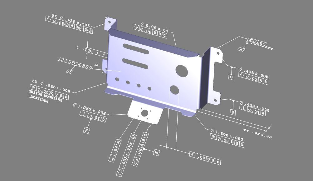
deliverable The benefit of a fully detailed parts is that the designer gets a second look at the part for errors or a better design before release. The fully detail document is much easier to check, review and handle. we all know that more information never hurts. This extra look can save thousands of dollar in errors, engineering hours and slipped schedules later down the process, especially if you do not have a formal checking process. The partially detailed AID. This is where the short cut in the engineering deliverable started showing up. This is where you only detail the mating features. Mostly using GD&T. The non-defined features are controlled by a profile tolerance. I find this a bastardization of the use of the profile tolerance. All of the other information is included like a standard drawing, material, finish, process, etc. I feel this lack of information opens the door to Murphy causing chaos in overlooked errors and a thorough design review. I had a great contract turning minimized GD&T AIDs as shown below into completely detailed AIDs. Today, suppliers just work around the demands by a companies that have an incredible lack of applicable knowledge of the purpose of engineering documentation. These parts were designed by designer whose only requirements was experience on UG. I think many were automotive designer. Sorry about the quality it was delivered as a .jpg. "If it is difficult to detail it will be equally difficult to machine!"
The fully detailed AID in the form of a PDF and 3D model is the standard deliverable now used by most small companies and requested by the suppliers. It takes nothing more than a compatible CAD/CAM system that can import the native or neutral 3D CAD model and an Adobe reader to access the information. A very simple with little that can go wrong. The model and AID when compared will show any discrepancies. This is a final stage where any errors can be found. 3. This Brings Us to the PMI.
Years ago I was using CADKEY. We could easily
dimension in 3D space. So I looked at PMI as a professional draftsman
and laughed. I knew this would fail from the start. It added nothing to
the process and took much of the definition and scrutiny of the design
away. Minimizing information is never a good thing. As a CADKEY dealer I supplied virtually every Boeing supplier with Catia 3, 4 and 5 compatible 3D CAD software. One day I started getting calls from the suppliers telling me that Boeing was not sending paper prints. They were sending the PMI. It was quite bizarre that Boeing did not prepare their suppliers for this drastic change in documentation. These were some of Boeing's largest suppliers.
CADKEY or Catia? Boeing’s Billion-Dollar 3D CAD Mistake! Soon the suppliers were forced to have a seat of Catia 5 or a Catia viewer call Enovia. They were very confused and went through a variety of solutions. They were not happy with this costly solution. Not only in the expensive Catia software but having to train someone to use it. This added a new level of cost to the manufacturing process. Sadly, engineering productivity did not reflect this convoluted process as expected. But I am sure no studies have been done, if they have it would be "Lies, damned lies, and statistics"
I was hired to completely detail the parts for many of the
companies for inspection. This was quite lucrative for me for a couple
of years. Dassault convinced Boeing that Catia 5 and their PLM system could now replace the smooth running standardized proven engineering system Boeing had used for decades. This led to the elimination of the Drafting Group and Document Control. The Death of the Draftsman or “Where has all the talent gone?” This added a new level of complexity to the Boeing
supplier. They devised many workarounds. It was getting worse. Catia 5
was the least interoperatable system so many of the models were coming in
corrupt. To try and solve this problem, Boeing requested that the suppliers purchase a validation
program to assure the model were the same as the model that went into
the CNC. Sort of an apples to apples solution.
The major problem with the PMI was there was no
standard viewer. If you couldn’t afford a Catia 5 seat or Enovia there
were only a few importers that would read the PMI. In the beginning of this change I was involved in
the development of Adobe Acrobat 3D in 2006. This would read the Catia 5 PMI and
deliver the model as a STEP. I was very excited to have another $495.00
product to sell my CADKEY Boeing suppliers. But just as it got released
Adobe sold it. You can get it now as Tetra 4D. I am not sure why Adobe
abandoned this product I thought it was quite viable cost effective
solution.
But Boeing was pushing the large suppliers to buy seats of Catia. It was funny I was still
supplying CADKEY with native
Catia 4 and 5 translators. I will not go into the Catia 4 and Catia 5
incompatibly fiasco. But CADKEY had a much better solution. It was used
by Boeing to convert Catia 5 and other native files to Catia 4.
Slowly the suppliers were falling into step. But the PMI is a somewhat viable engineering
deliverable. So let’s see what is required. Pre-PMI with Catia 4 (Much more stable and usable
system) A compatible CAD/CAM system and the Print. Cost to the supplier? Nothing. After PMI A current seat of Catia 5 ($12,000 Basic plus
maintenance)
Or A seat of Enovia (I am not sure the price) You still need to be able to read the native Catia 5 model. Boeing will not send you a STEP. Catia 5 has a problem creating a good STEP file. Or A compatible PMI importer – Kept up to date with
the current Catia 5. $695.00
Then now add: Verification software - $7000.00 Now for inspection. You have to have a special
inspection process. Cost? Who knows. Even if you wanted to do it
manually, that is now out of the question, without detailing the parts
yourself. That is the suppliers side. Yes, much more
convoluted but doable. Now for the effects on engineering. Enter PLM. Yes, this is where is started. Why PMI? I am sure that PLM looked at the current
3D CAD systems and realized that there were 3 separate files to
maintain, the Model, AID (drawing) and the Assembly. Not only with the
separate files but with the synchronicity necessary between the part and
AID (drawing). They looked at putting the dimensions in 3D space which for some
reason seemed logical. It is truly a silly system. But they do have only
one file to maintain.
We mostly see examples for single parts. What about inseparable assemblies? Today I create sheet metal enclosures with all of the sheet metal and fasteners included. What do they do with a PMI? Do they have the separate PMI sheet metal and then have an assembly? I have never seen one as an example. Do they have a separate parts list or is it included with the PMI. I have even seen section views in PMI. UH… sort of defeats the purpose, doesn't it?
Engineering Ignorance Defined III The PMI cannot be fully detailed. There were AIDs only showing the GD&T so PMI immediately move to minimizing the dimensioning to only a few limited dimensions covered by a feature control frame and all of the other faces controlled by a mass of profile feature control frames. I would look at a Boeing PMI and you would see most of the faces not covered. I looked for an UOS (Unless Otherwise Specified) note, but there was none to be found. I also didn’t see any other information. My Boeing associates say there are, at least, two other documents that travel with the PMI. You just have to shake your head. To make this system work Boeing has added Band Aid after Band Aid, making it even more convoluted. It is so bad now they have a Producibility Group reviewing the parts after release. TRUE INSANITY just to replace the standard drawing? PLM includes the PDM, I think. This is all so confusing.
PMI is the new deliverable, but it is delivered in
the native CAD format. So do you handle this with PDM or is there
another data management system only for the PMI? HERE IS WHERE IT FAILS There is no way to standardize a native
3D CAD file as a
deliverable. Today I have a PMI importer solution. Yes, you knew
I would get you to look at my products.
ZW3D imports the native files and PMI information
of Creo, NX, Catia and Solidworks. Of course, the advantage is that you
have fully professional CAD/CAM system that can directly modify and
utilize the parts. Much better than Tetra 4D that just lets you save
them as a STEP. But this got me thinking. Today I can import PMI in those native formats. But I can’t read Inventor and IronCAD PMI. No one else can read them plus the ZW3D PMI. Now we have 5 different PMI formats. How do we stay current without having the current software? ZW3D or any PMI importer has a chore ahead of it if it wants to stay current with all 4. Unless of course the major CAD vendors coordinate the releases of their new versions. We know there is no backward compatibility. This is the failure. Unless they can standardize the PMI output we will have to live with this level of incompatibility. It even gets worse as you start to archive your engineering documentation. You have to keep the Native system forever. With the 3D model in a neutral format and an PDF AID (drawing) and a hybrid 3D modeler your archived engineering would always be available without any consideration. I suppose I could sell you ZW3D. Do you really think the major CAD systems are going to include PMI importers. Here is a complete study by the National Institute of Standards and Technology which is a government agency studying PMI. None of these folks are 3D CAD engineers or even draftsman yet they are accepting the PMI as a viable standard. As you can see by this study MBE/MBD/PMI nothing of the sort even though it has national standards that define it. But how can it be a standard if it is in a unique native CAD file? MBE PMI Validation and Conformance Testing Project
This article shows the lack of understanding of the
simplicity of the “drawing” much less than the concept of the model and
PDF AID (drawing). But they are wasting their time. Engineering today is not managed by the knowledgeable engineering of the past. It is managed by PLM and InfoTech experts that have never sized a hole for a screw. Much less read or understand a drawing or a PMI for that matter. Conclusion Here is the only other article I have found where someone sees the limitations of MBD. The Argument Against Model-Based DefinitionWhile I really don’t have a dog in
the PMI as a deliverable fight. We have the potential for poor
engineering due to the lack of easy review and checking with this
process. But that is not the major problem. It is bad enough to have our engineering based on a
myriad of incompatible CAD systems, but to not have a standard
engineering deliverable is costing the industry a fortune. You cannot
use a native CAD file as the engineering deliverable. We can now get a 3D PDF
directly out of most the systems today, I am sure that adobe could
include the PMI and model as they did with the Adobe Pro 3D. But the model would have to be in a certified neutral format. The major CAD vendors would have to go through a process to assure that it was a good usable model. We have to realize these models are going out to a myriad of CAD or CAM programs. We must start taking interoperability serious. God forbid the major CAD companies would have to
meet a standard 3D model as defined by the industry. Can MBE work?
Yes, it can. It has to be in a tightly
controlled system that has little room for error. Everyone has to be on
board. If you include one non-compatible CAD or CAM system, the system
has to be flexible enough to accommodate it. This limits your suppliers
and increases costs. Cost effectiveness and commonality is the reason
for the development of new standard systems. The worst aspect of MBE, is
that the minimizing of engineering definition is very problematic to the
engineering process itself
But even the NIST has fallen to the
individual whims of the major CAD vendors, by actually doing a study
on the different native PMI deliverables. Solutions?
Force the Major CAD companies to
comply. Form an industry board and define the standards for the PMI
deliverable that can be read by a readily available importer. OR We could bag the whole PMI solution and go back to the Model and the PDF AID (drawing). Which all CAD systems could comply today. You could eliminate PLM and move back to a document control system. No longer would an engineer need to be in data management except inside the CAD PDM system. But even the designer would look to the standard engineer deliverables, the Model and PDF AID before going into the PDM system to find the native files. Just Imagine the PDM system like the vault only accessible by those trained in the CAD system operation. Leverage Your Engineering Data - Sales, Publication and Marketing Checking, Design Review, Manufacturing and Data Extraction! But I even have a better solution for a standard
engineering deliverable and document control. The Fourth Engineering Deliverable - The Future of Engineering Documentations The Embedded Title Block! A PLM Solution! The Ultimate Engineering Document Control System
If you are in a management or academic position and you would like to explore other related CAD subjects please feel free peruse some of my other related articles. Viewpoints on the 3D CAD Industry Or give me a call
TECH-NET Engineering Services!
If you are interested in adding professional hybrid modeling capabilities or looking for a new solution to increase your productivity, take some time to download a fully functional 30 day evaluation and play with these packages. Feel free to give me a call if you have any questions or would like an on-line presentation.
Joe Brouwer |

.jpg)
TECH-NET ASSOCIATES | RENDERING OF THE MONTH | CAD•CAM SERVICES
HARDWARE | TECH TIPS | EMPLOYMENT | CONTACT