IRONCAD vs Inventor Lesson 1 Assembly 3D Modeling Techniques DefinedTrue Top Down Assembly/In Context Design vs Separate Part DesignWith Streamlined Sketching/Feature Based Modeling In a Single Model Environment
The modeling technique is
hugely responsible for the level of productivity. Those of you that
are only trained in the constrained sketching world of the major CAD
systems
are truly limited by not using the freedom of Streamlined Sketching
and Feature Based Design,
that is available in even the most Pro/e-ish of CAD systems. If you
or your
designers are designing in these very unproductive and time
consuming processes it might be time to review your standard design
processes. Don't have any do you?
These
lessons started out as
product comparisons, but quickly turned into a study in 3D modeling
techniques.
When I introduce IronCAD's very
flexible design paradigm I have a hard time to get the Pro/e clone
users, like Solidworks and other programs to understand the drag and
drop design paradigm.
Download
IronCAD/Inovate and take
the one day and 17 lesson course. I get rave reviews from my new
customers. Give it a try, this is a fully functional 30 day
evaluation with all of the native translators so you have access to
your legacy engineering information.
IronCAD Self-Pace Training Course I saw the
following Inventor YouTube tutorial and thought I would give it a
try on IronCAD. I have to tell you it is almost tortuous to watch
the Inventor presenter.
I remember having lunch with an old
friend and engineering associate that moved to Solidworks for his
consulting service. He said he create each part separately and
inserted them in the assembly. He was an old CADKEY user. CADKEY was
a single model environment and I suppose he didn't know he could do
top down/in context design. I
have tried to do top down/in context design in Solidworks and
totally failed.
I was a bit surprised the Inventor fellow
did not use the capabilities of Inventors top down design. I took a
Sales/Tech job with a company that was going to represent Autodesk's
Manufacturing Solution which was based on Inventor. The tutorials
were excellent and they started you out in top down design. Inventor
is a bit better but all of these programs including NX create
external parts. You will see a huge difference in IronCAD's true
single model environment.
Inventor is a constrained sketched based
system as are Fusion 360, NX, CATIA, Solidworks and Creo. In the following
lessons you can see that this modeling paradigm is use throughout
the industry causing millions of wasted hours. If I remember right,
Inventor now includes primitive shapes!
I have never done this! IronCAD is designed for top down design!
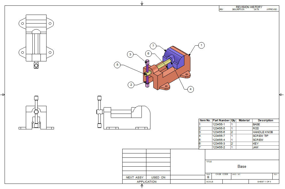
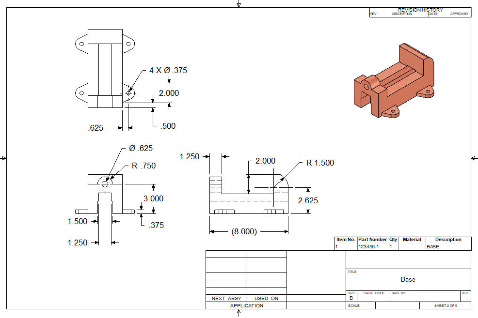
The reference drawings are at the end of the lesson.
Assembly is the very
best feature of IronCAD. With its true single model environment it
offers the highest level of productivity. Watch how we use drag
and drop with a minimum of sketching to complete this job in no
time. There is no better program that can manipulate parts and an
assemblies in a 3D space.
While creating 3D models from a drawing is the very best
way to learn 3D CAD and maybe some design techniques is does not
expose the designer to the design flexibility necessary in product
design. IronCAD is all top down due to the single model environment.
Creating mating parts is a cruise. But modeling is just one aspect of a
well designed productive 3D CAD system. IronCAD vs Inventor
I would do a
video, but I really am not good at it. So I will show you step by
step. I will try and get IronCAD support to create one. They are
very good.
I always create the part before I watch
the Inventor Video, so as to not taint my process. Of course,
there are a multitude of ways to create a model. There is no right
way, just more productive ways. But from what I have seen from these
very complicated processes done by the Inventor presenter, it is not
just limited by the 3D CAD system.
I have to say this is
incredibly simple. But the NX presenter has been
indoctrinated into these designs techniques. It started with Pro/e (Creo)
and has been the way the sketch, constrain and assemble. The
Solidworks clones are costing the industry millions, if not billions,
in lost productivity.
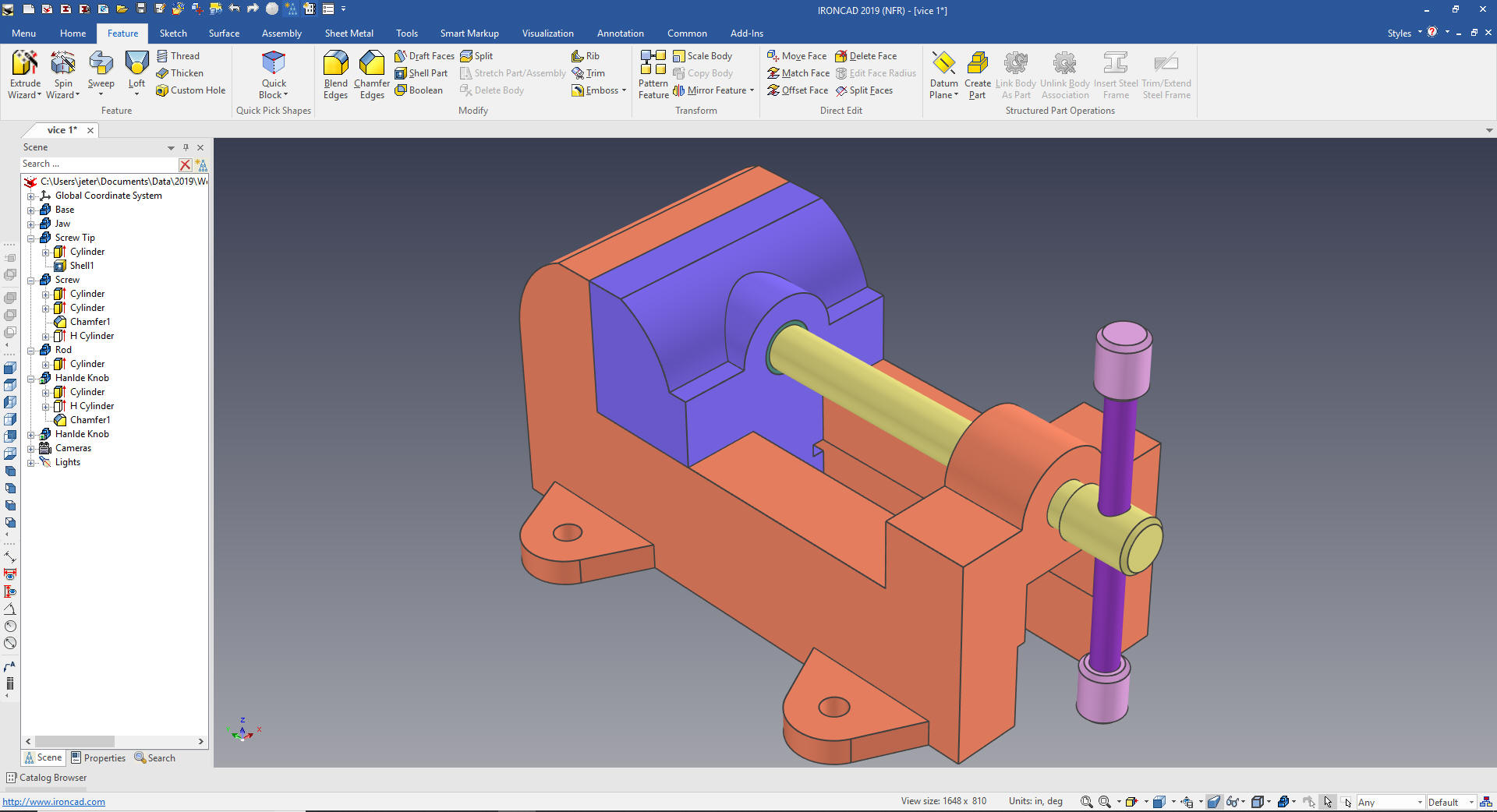
Here is IronCAD.
With IronCAD's single model environment
we do not have to prepare for it being an assembly. We just start
creating our part.
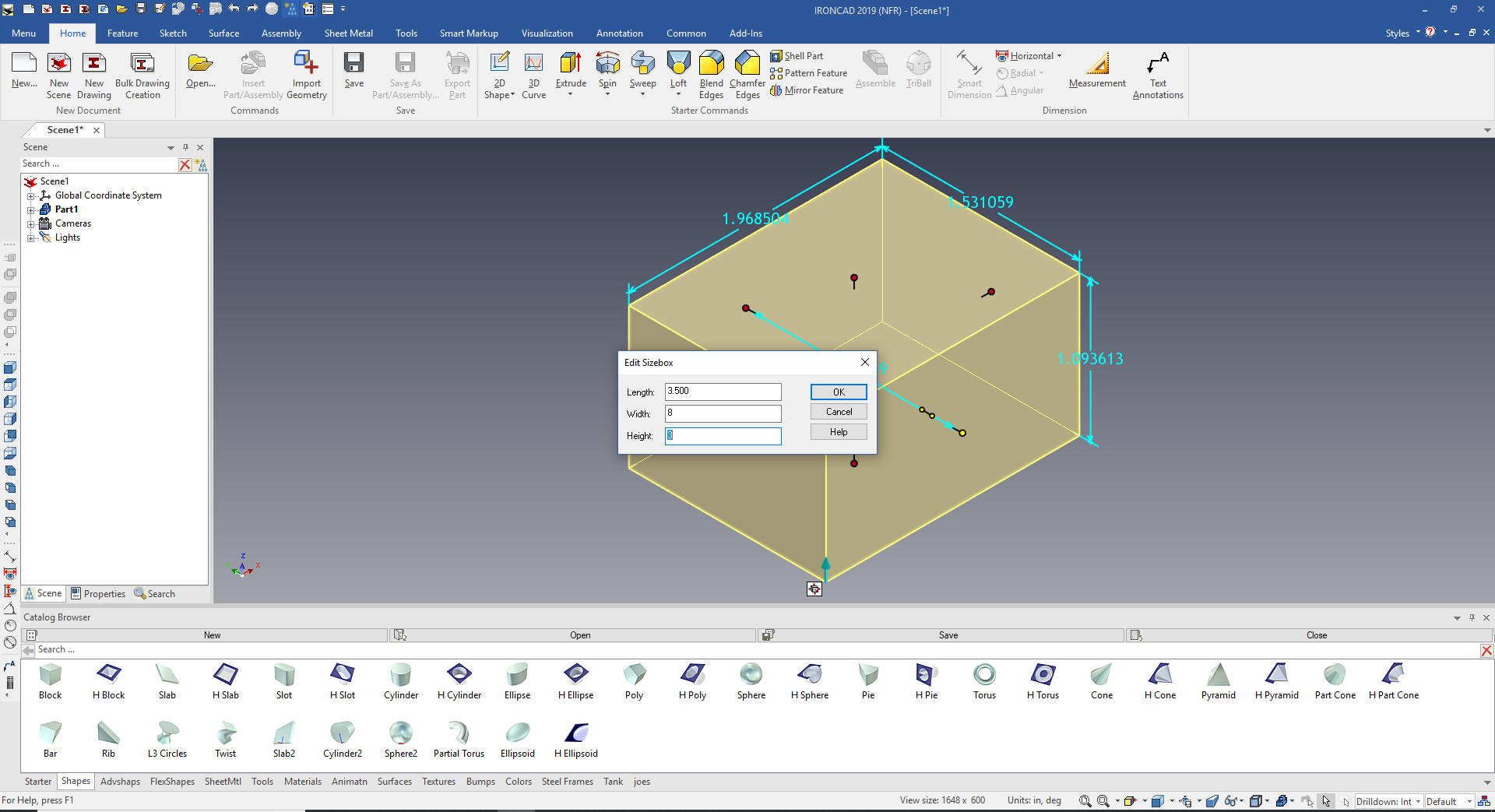
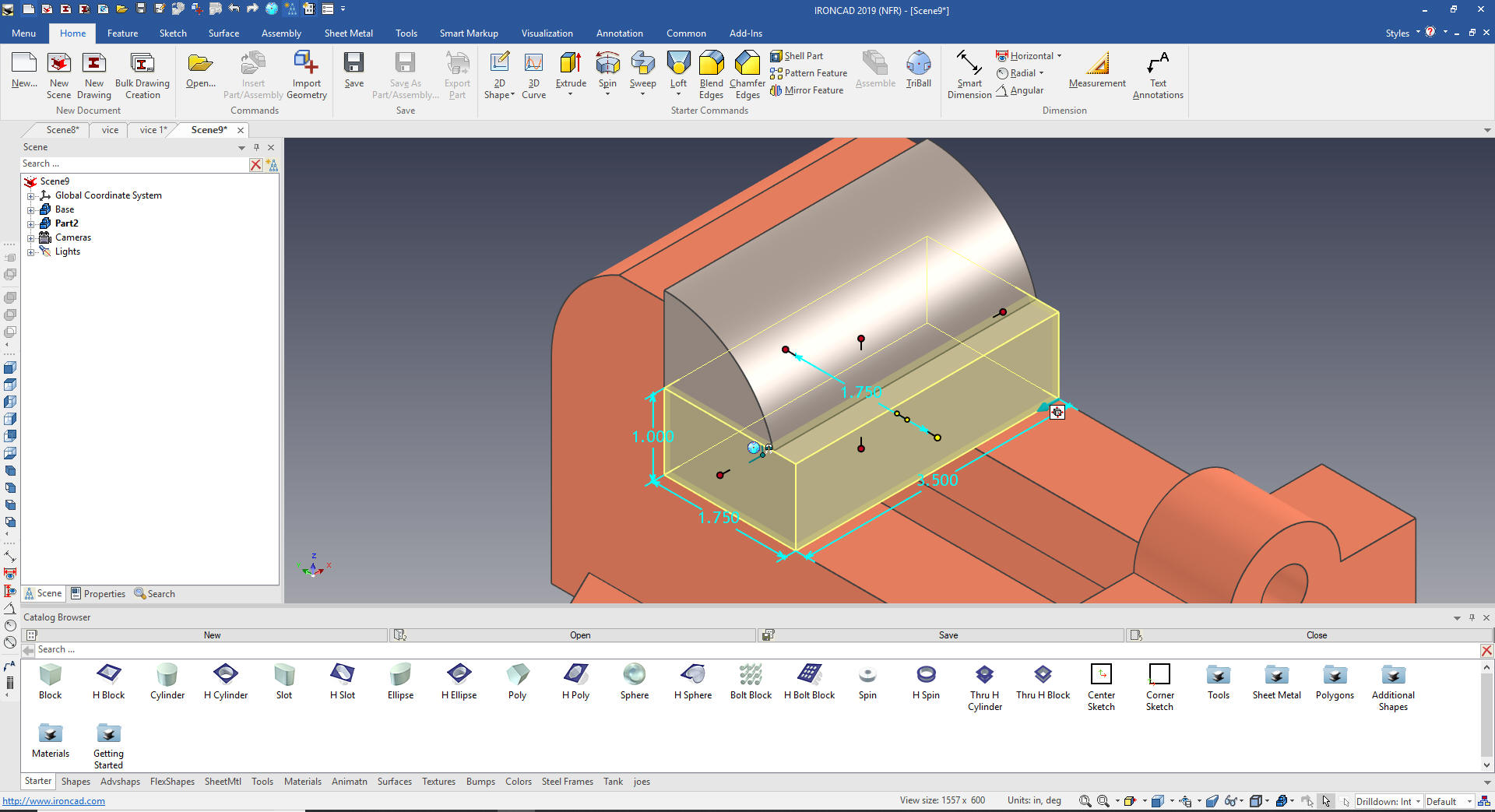
We will start by dragging and dropping a
block from the catalog and sizing it.
What are these shapes? We call them
intellishapes. All are based on sketches that can be edited.
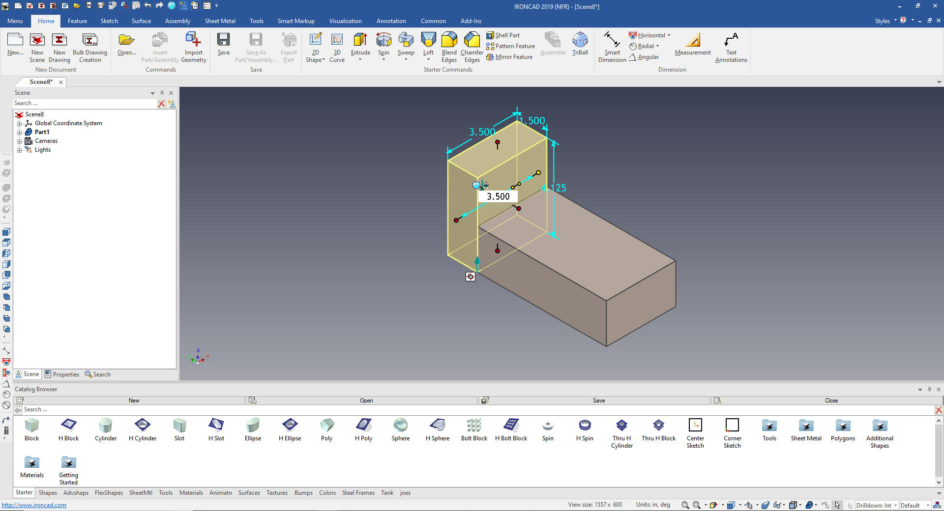
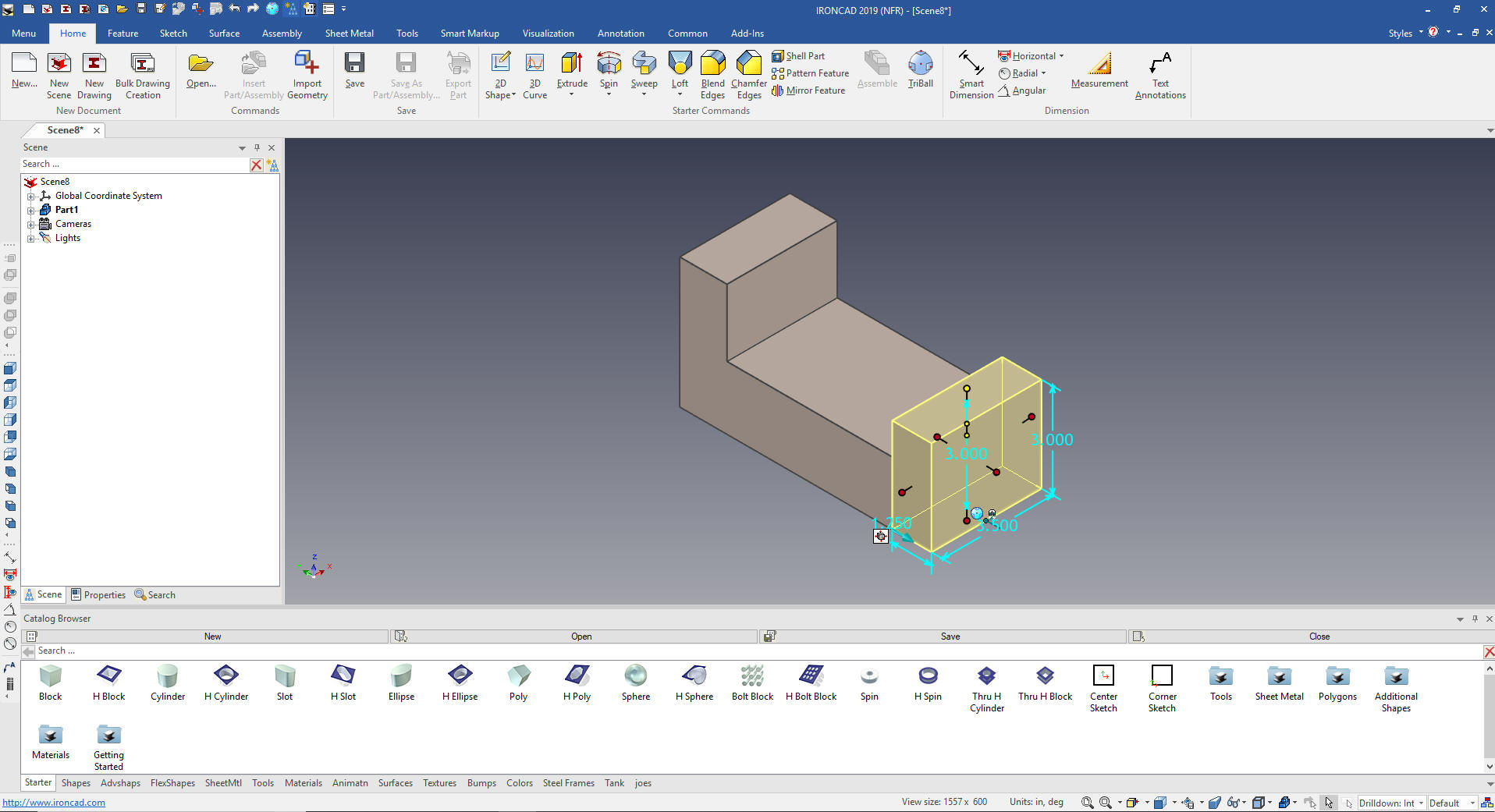
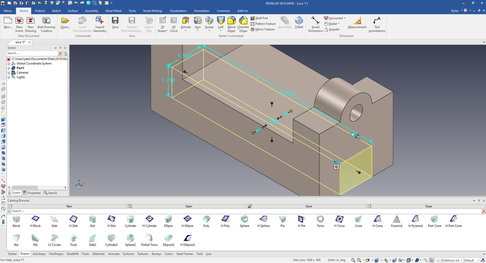
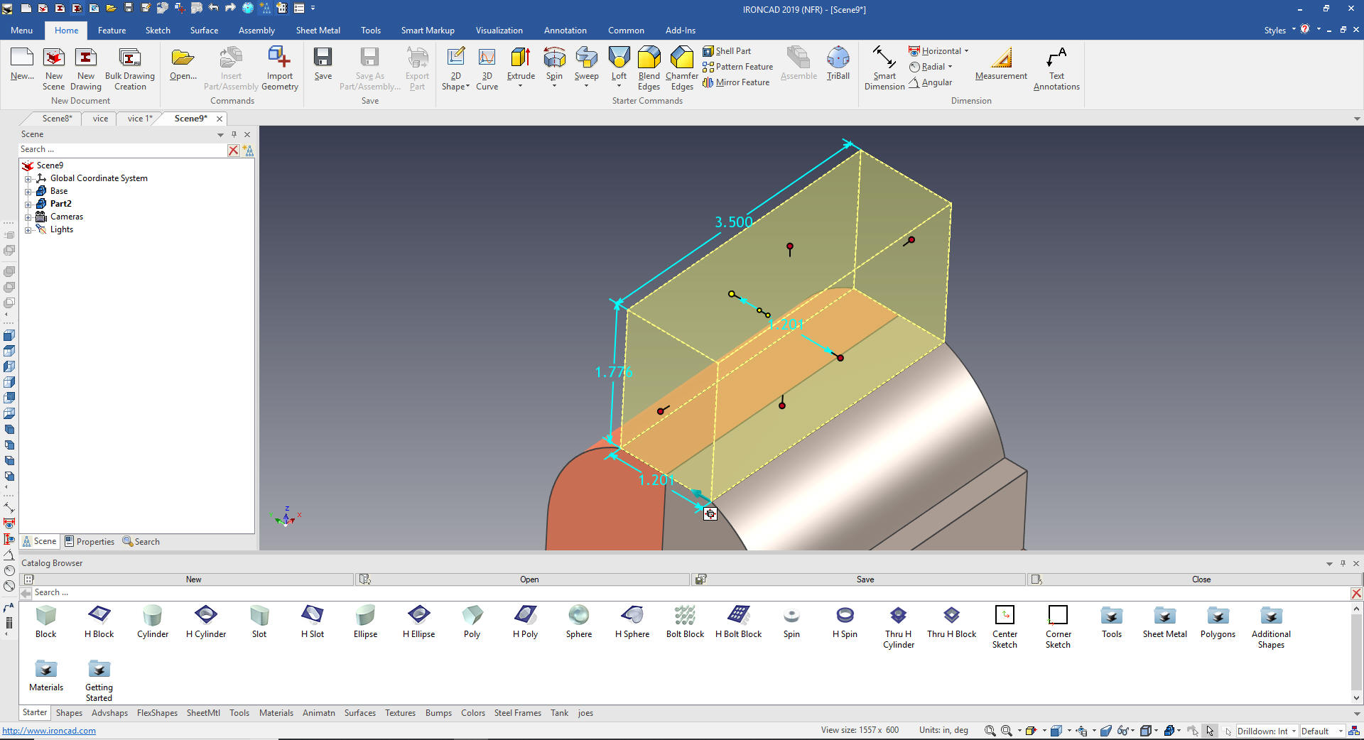
We then drag and drop a block on the
existing block locate and size it
We drag and drop another block on the
front of the exiting block and size it.
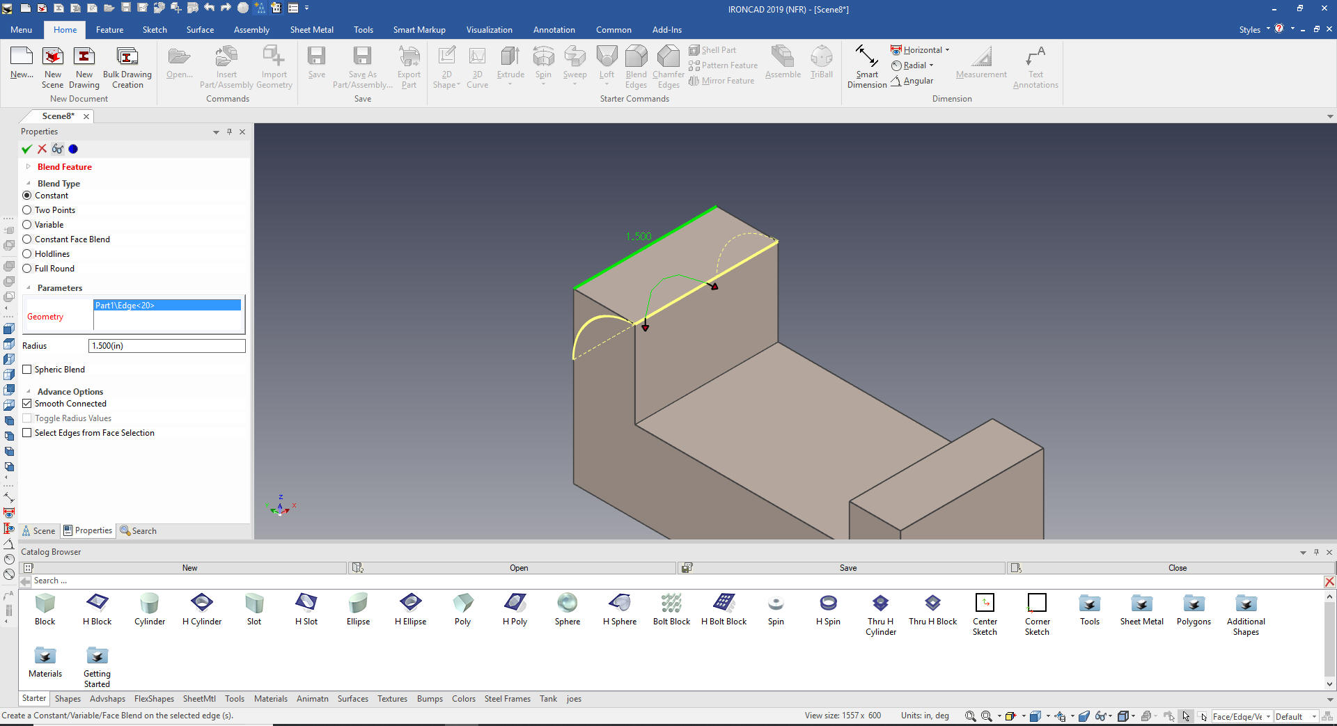
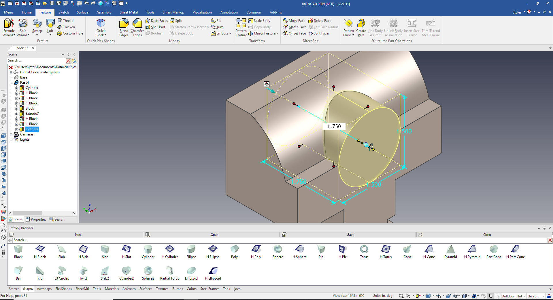
We put in a 1.5 blend
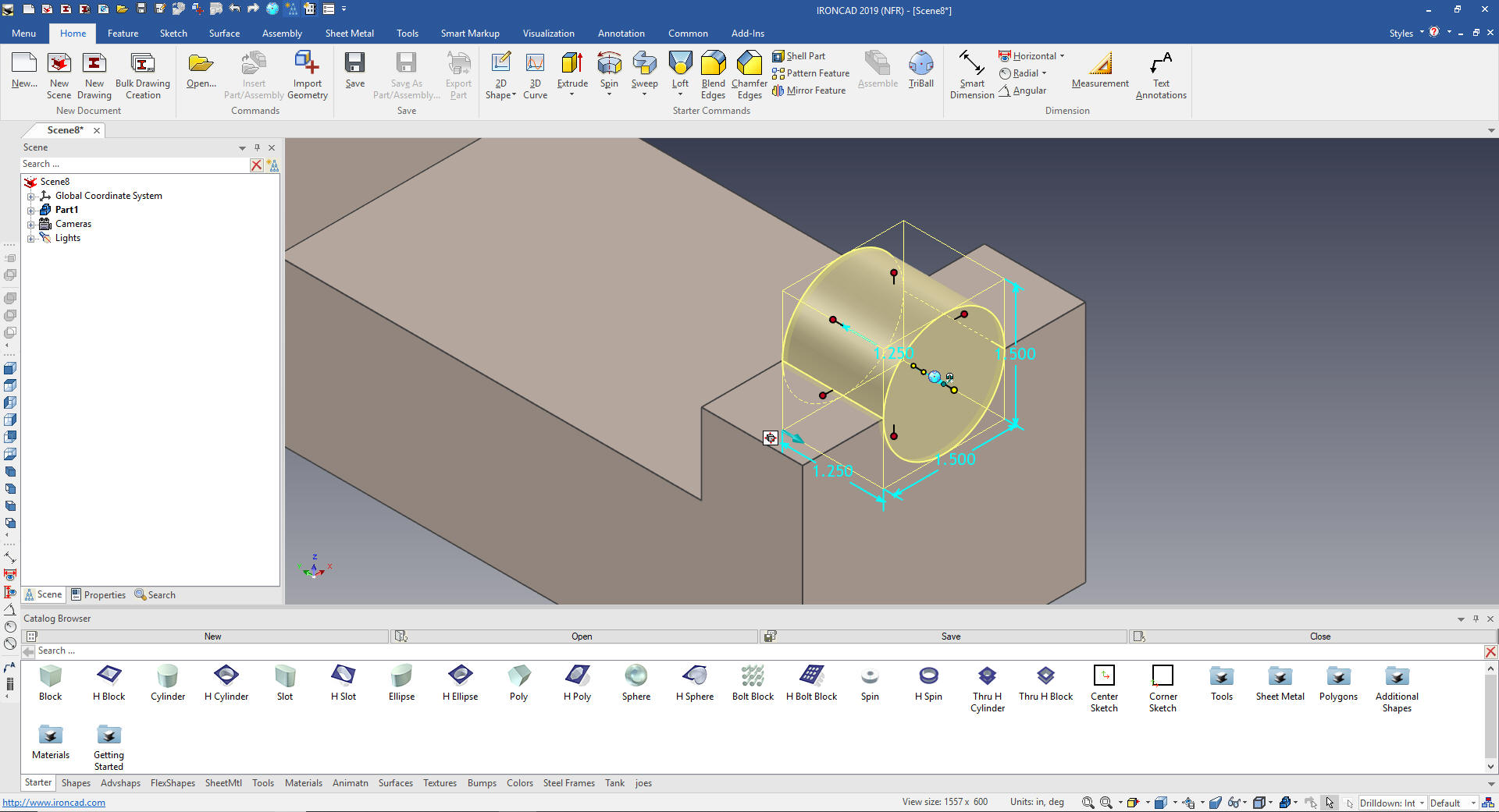
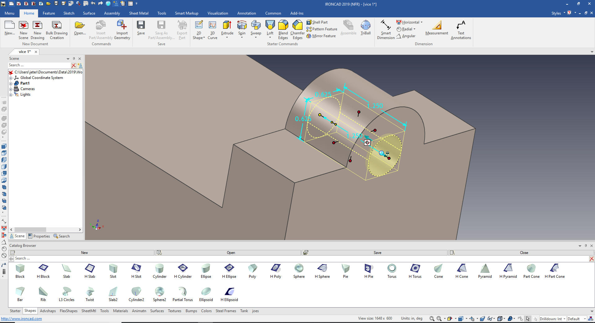
We drag and
drop a cylinder on the top front edge and size it.
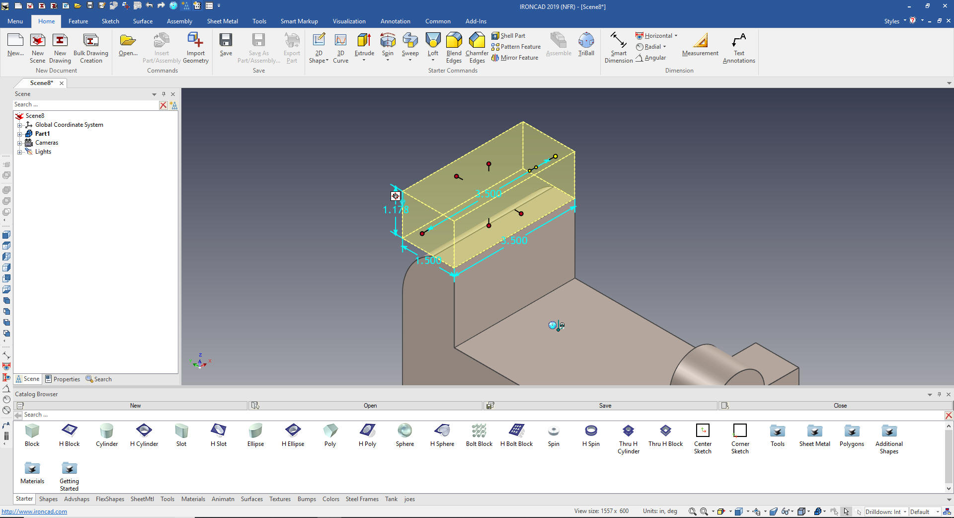
We drag and drop a hole block on the
center upper face and size the block. Nothing can be easier.
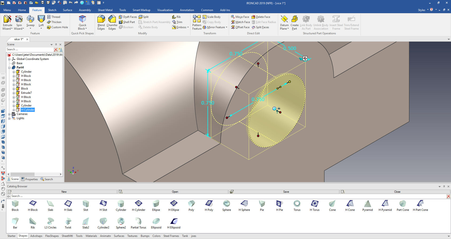
We drag and drop a hole cylinder in the
center and size it.
We drag and drop a hole block to
mid-point of the front face and size it.
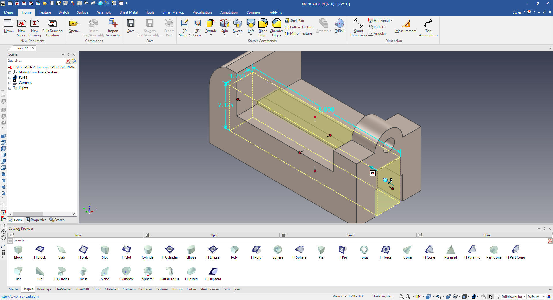
We
drag and drop a hole block to the top edge of the existing block and
size it.
Now
for the feet.
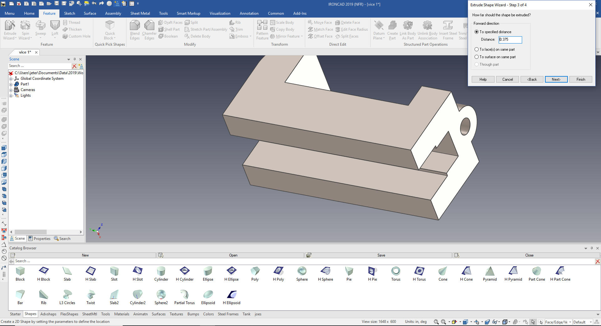
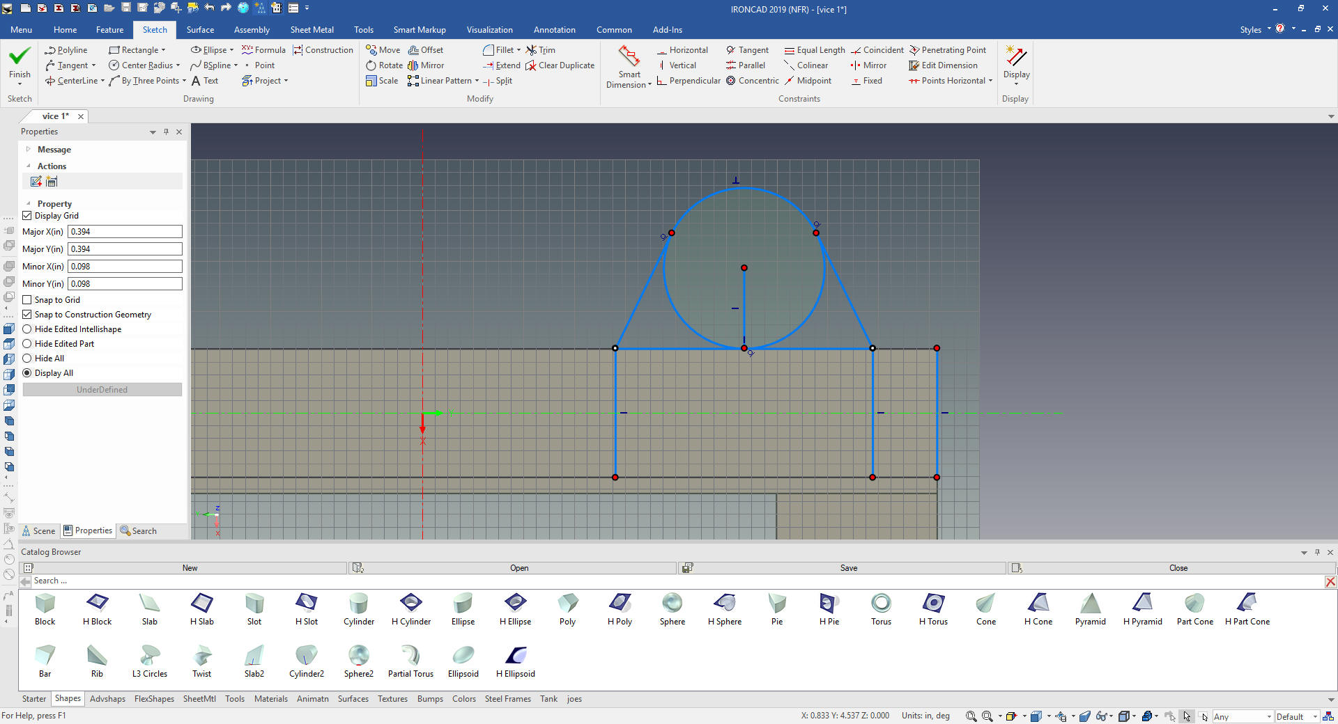
Using the extrude wizard we create a sketch
plane on the bottom face and set the depth.
I use
StreamLined Sketching. I project the relative edges then use offset,
trim, extend to create the necessary geometry.
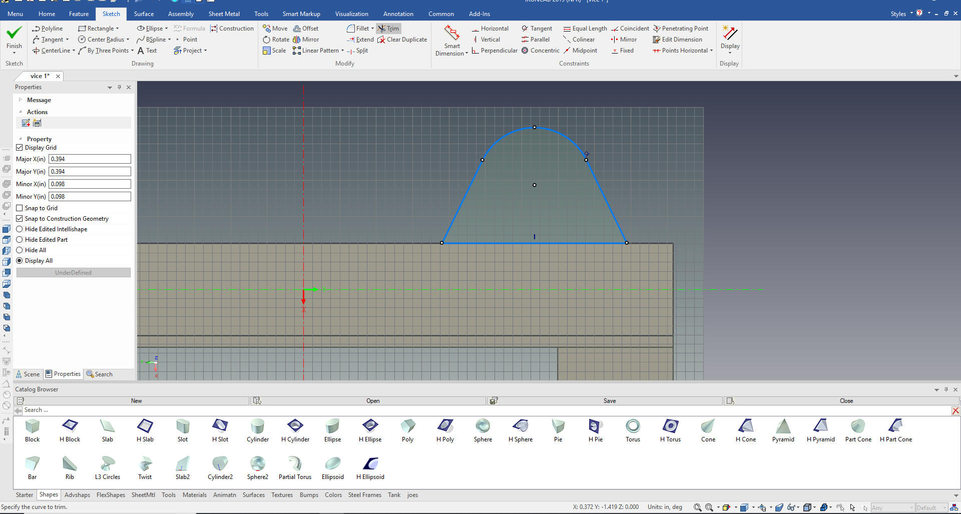
I
complete the sketch by trimming the geometry. No constraints. Saves
a huge amount of time. Notice I do not include the hole. I believe
all holes should be put in separately for ease of editing.
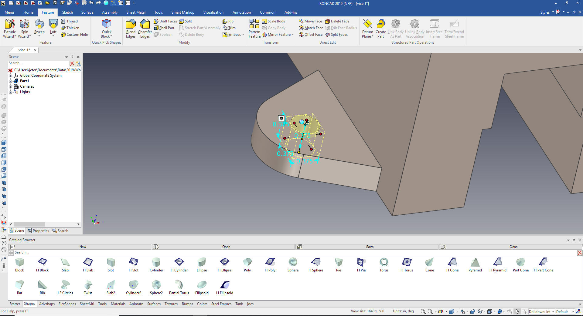
We
select okay which creates the first foot. Now we will drag and drop
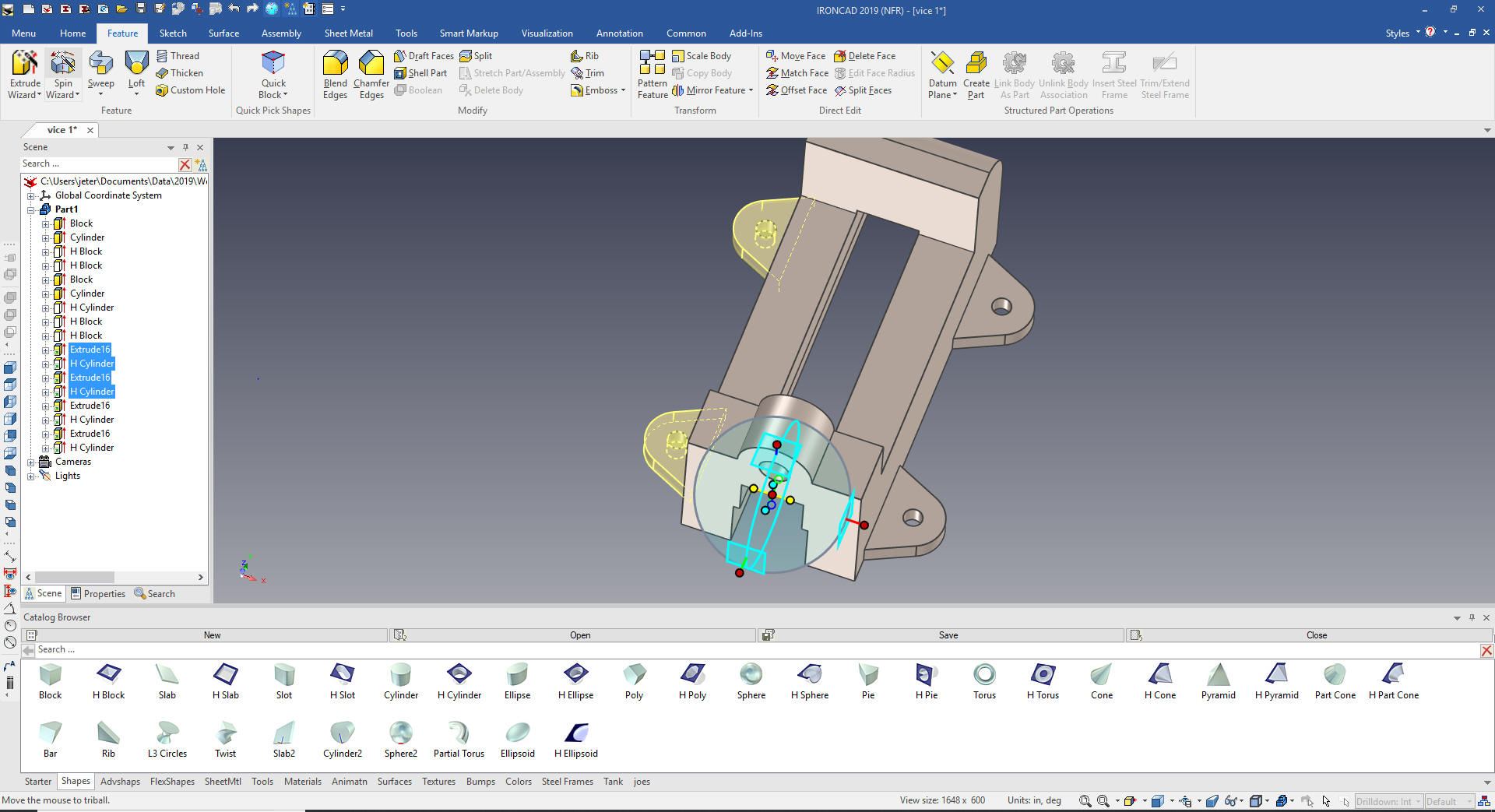
a hole cylinder on the center of the radius and size it.
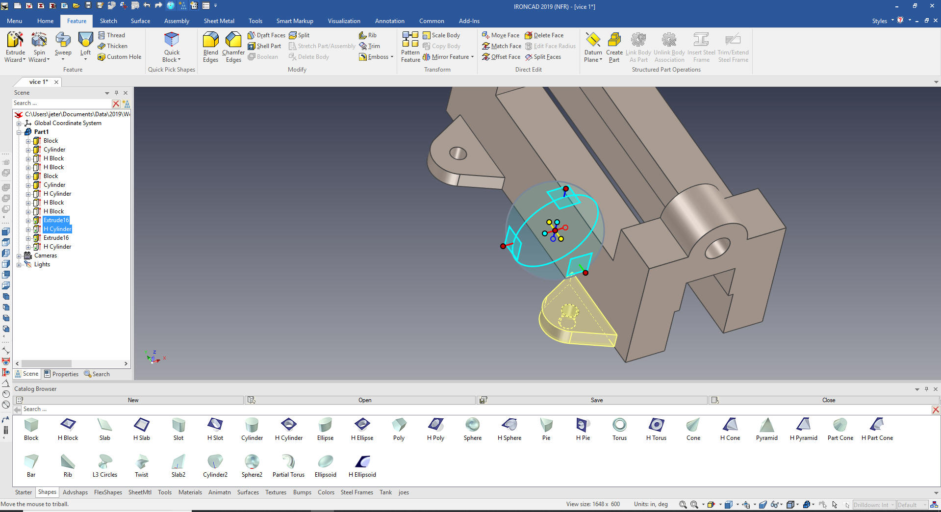
We
select the foot, as a feature, and hole, using the Triball mirror link the
features.
We
select all of the features and using the Triball mirror link again.
We push the spacebar to allow relocating the Triball for the
mirroring step.
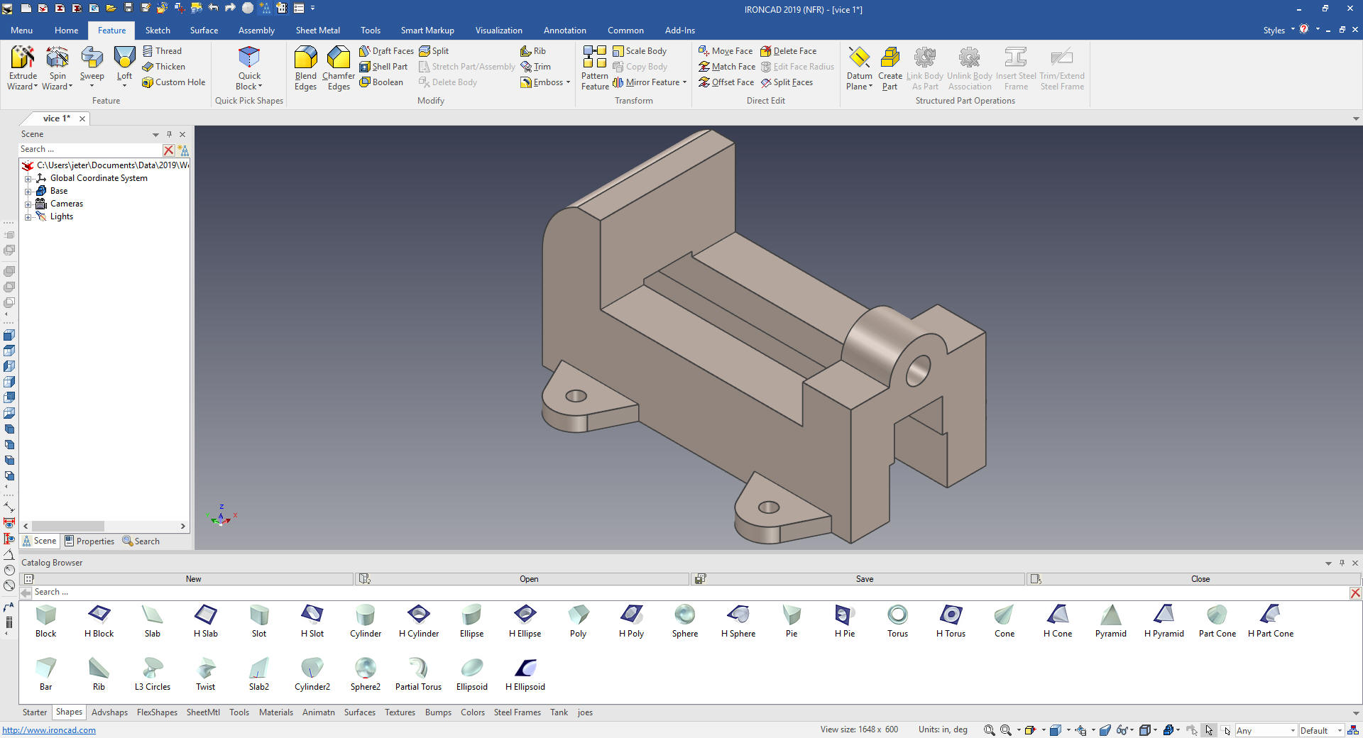
We
are done with the base. We name the part "Base"
IronCAD was designed from the ground up
for top down or in context design and has many functions that make it
much easier. You can see the time saved not only in much more
productive modeling but having the mating parts available for
reference.
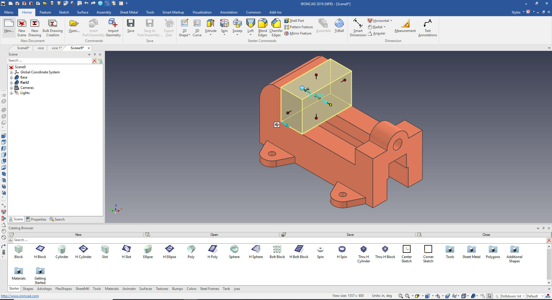
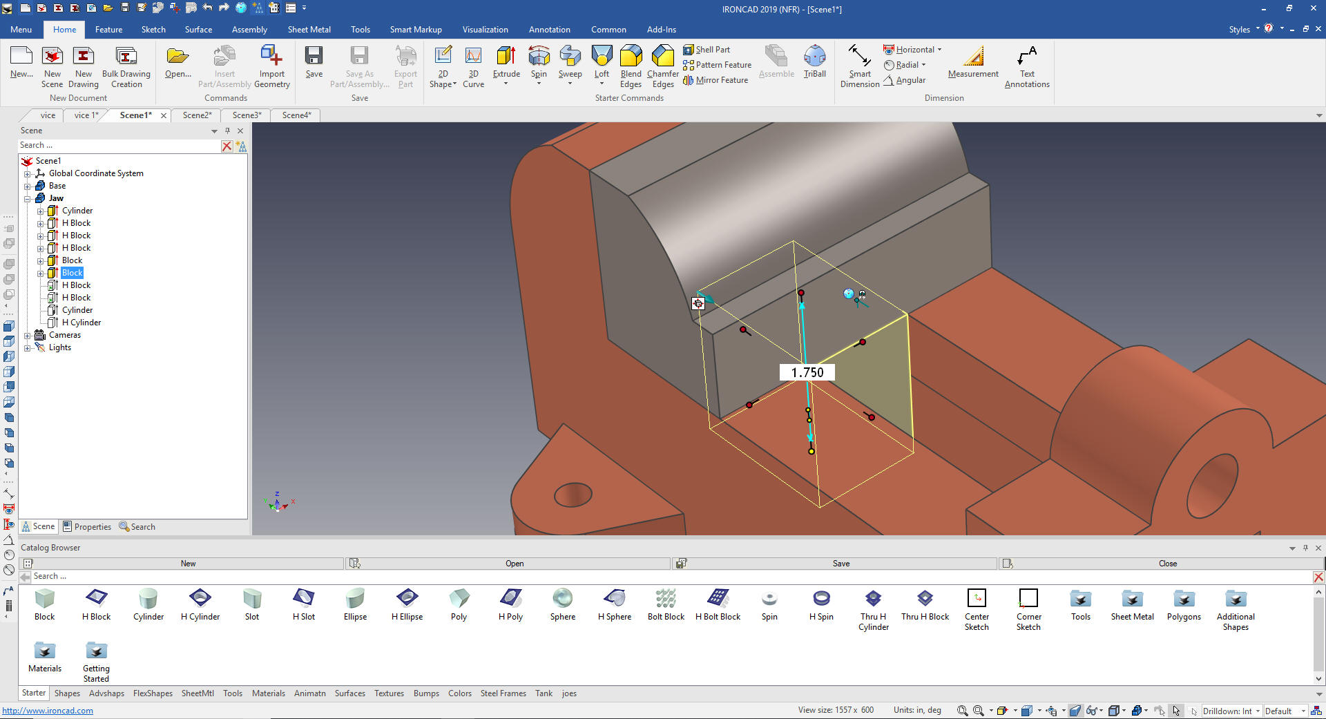
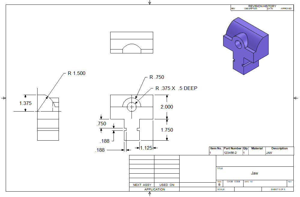
We will start by dragging and dropping a block on
the top face of the center of the base using the right mouse button that will allow
us to create a new part. If you look at the scene browser (History
Tree) there is a new part. We will change the color of the base for
clarity.
We size it and add the .125 to allow us to create a
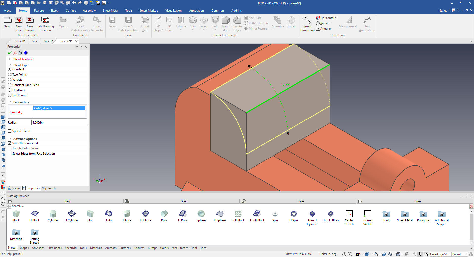
1.5 blend.
We put in the blend.
Now we
drag and drop a block on to the side and size. Most sizing is done
by selecting a a handle and select "To Point", we don't even have to
pull or push the handle.
We
drag and drop a hole block on the side face of the Jaw and size it.
We use the top of the Base to locate the bottom of the hole block.
Rarely do we have to define a dimension. It makes you wonder if
constrained sketching is modeling at all compared to IronCAD.
We
drag and drop a block onto the Jaw and size it using the base edges
and defining the length.
We
can hide the base and add the slots by dragging and dropping a hole
block, locating and sizing and using the Triball to mirror and link
the other slot.
I
will drag and drop a hole cylinder on the upper edge of the block.
IronCAD knows depending on how the faces are viewed how to orient
the dragged intellishape. We then size the cylinder.
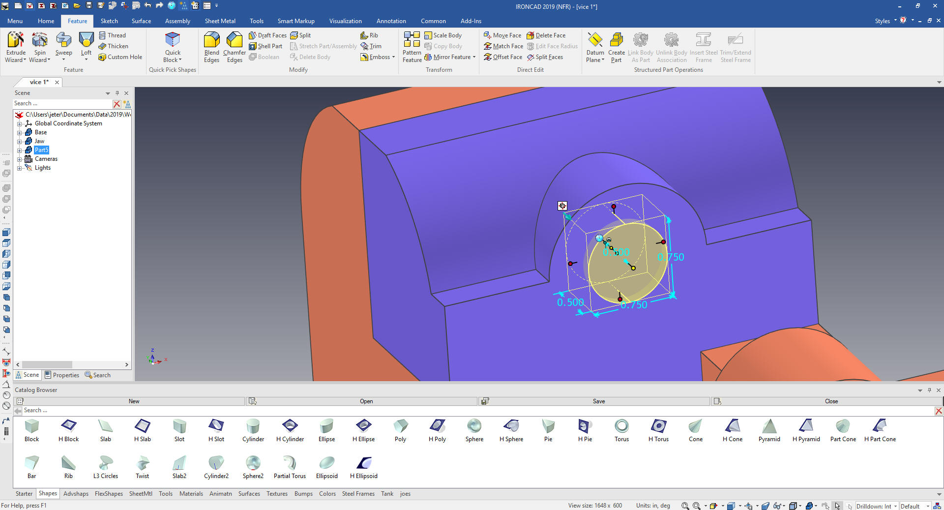
We
add the hole by dragging and dropping a cylinder to the center of
the boss and sizing it.
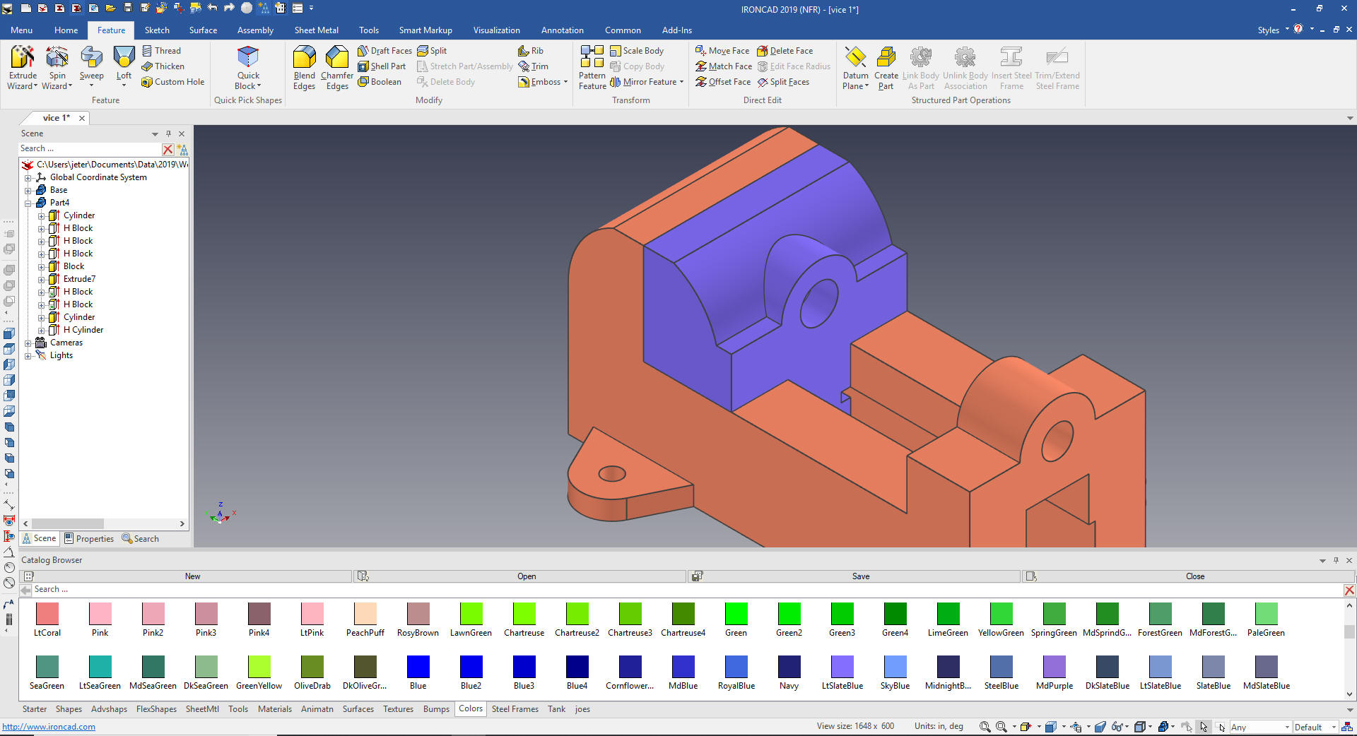
We
drag a color from the Colors Catalog, it gives you a much better
selection of colors.
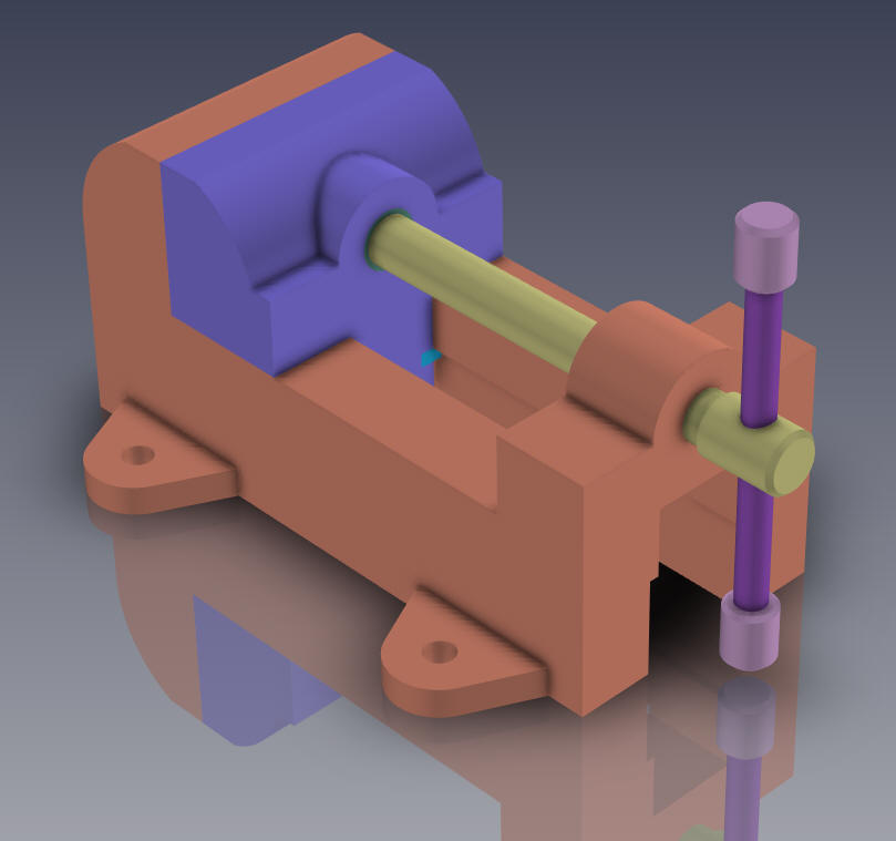
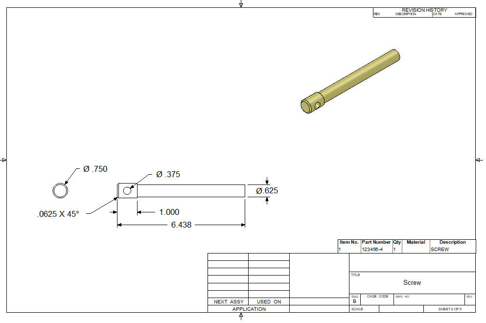
We name the a part jaw and get ready for the screw. This vice is
really only for CAD practice but I will make the screw and tip in
two pieces since it would not fit through the hole.
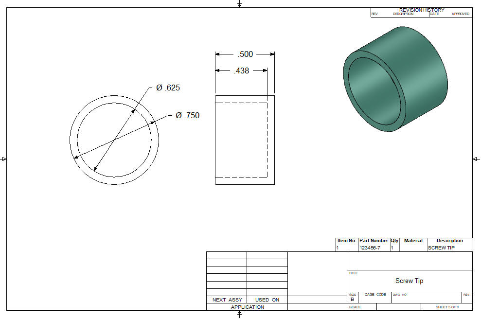
We drag
and drop a cylinder with the right mouse button to the center of the
hole to create a new part.
We will shell the cylinder selecting .0625 wall thickness with the
near face
open.
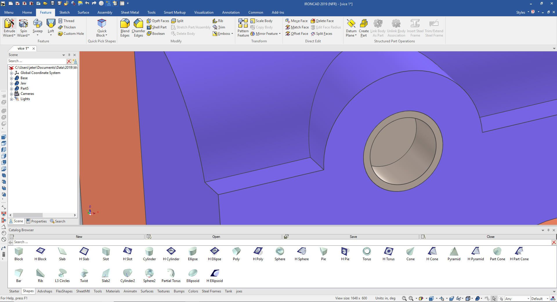
We
change the color and name the part "Screw Tip" and drag and drop
another cylinder to the center of the inside face again with the
right mouse button to create a new part and size it.
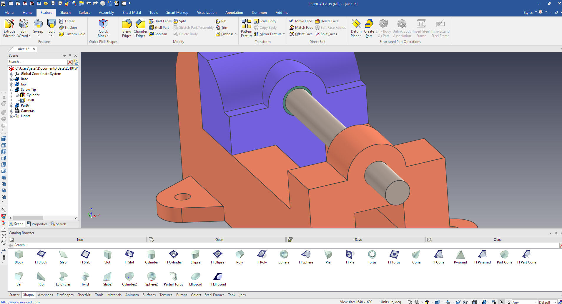
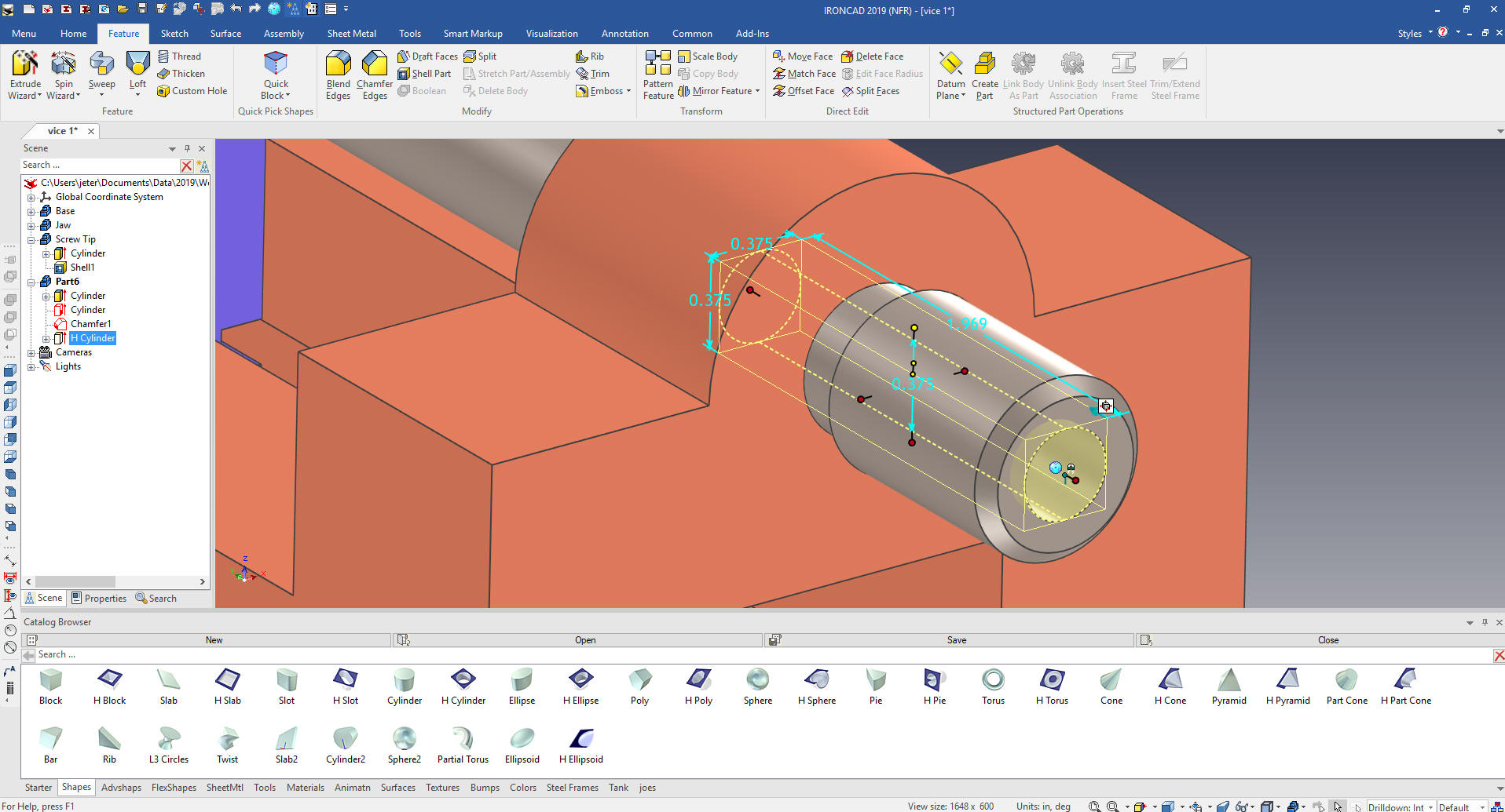
We
drag and drop a cylinder on the end of the shaft size it to .75 x
1.00 and add the .0625 chamfer. I have dragged and dropped a .375
hole to the middle of the end of the screw. This is a trick you
learn when working with shapes.
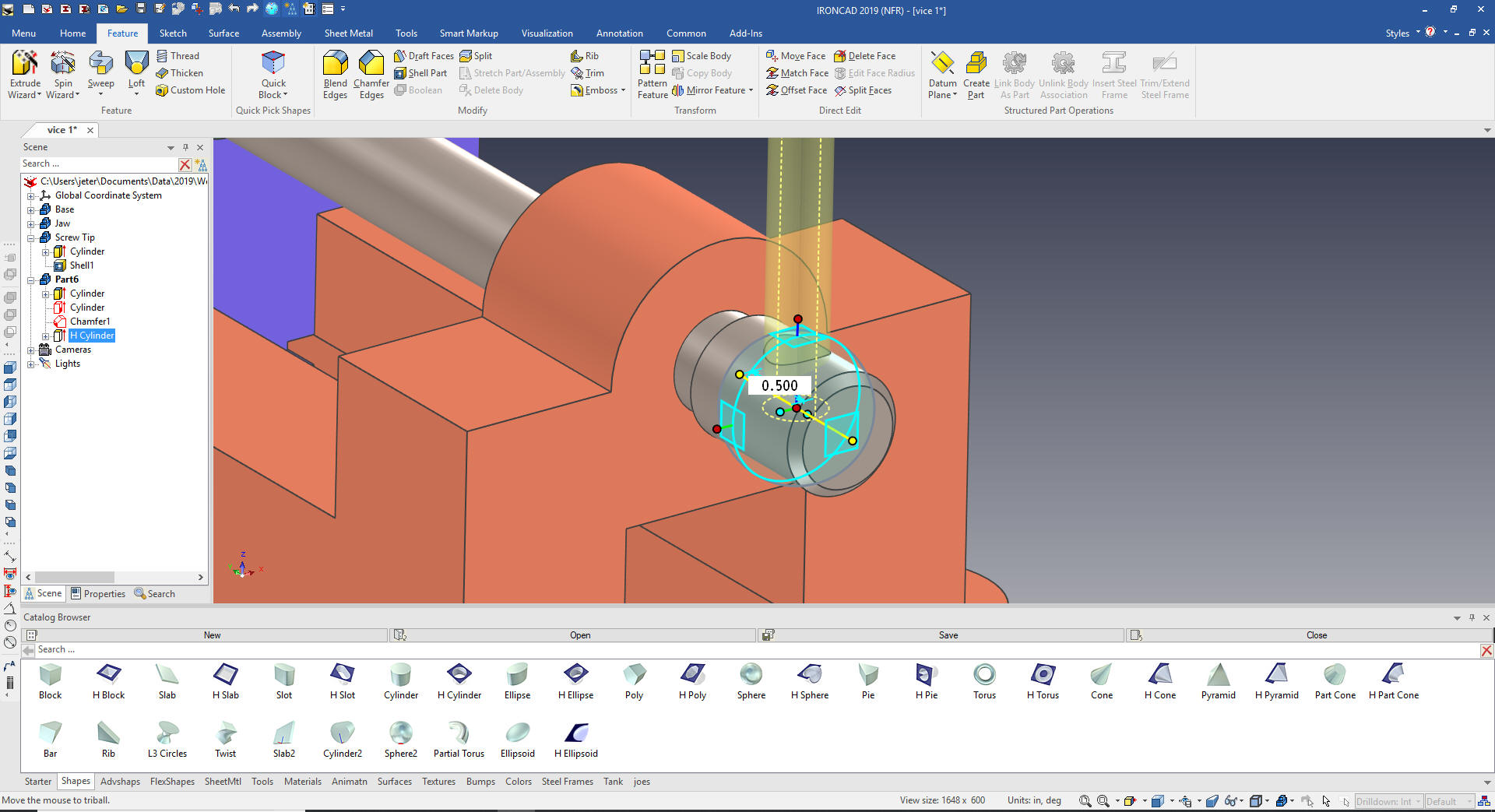
Using
the Triball we rotate the hole 90 degrees and move it into place. We
rename the part to screw!
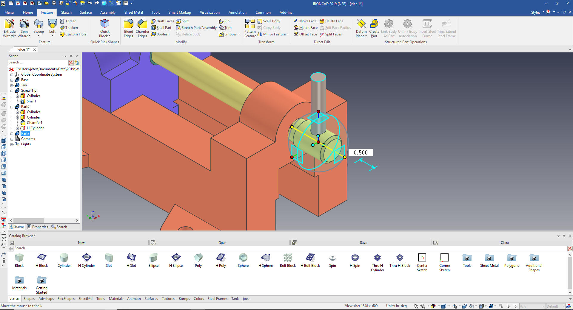
We
just pull the hole through and we are done with the screw. We change
the color of the screw and drag and drop a cylinder on the end of
the screw with the right mouse button making a new part. Like we did
with the hole we rotate it 90 degrees and locate it to the center of
the hole.
We
just size the rod and change the name to rod and change the color.
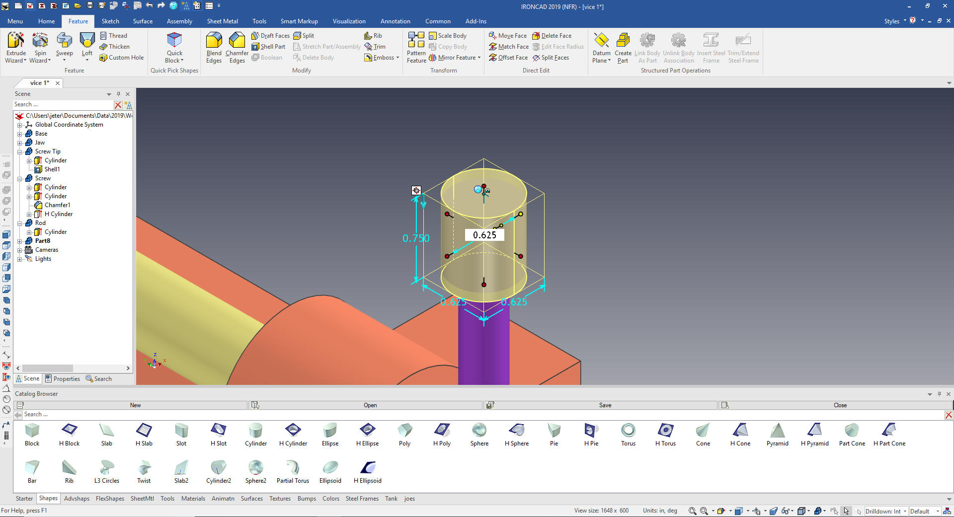
Now we drop another cylinder on the end of the rod again using the right
mouse button to create a new part and size it.
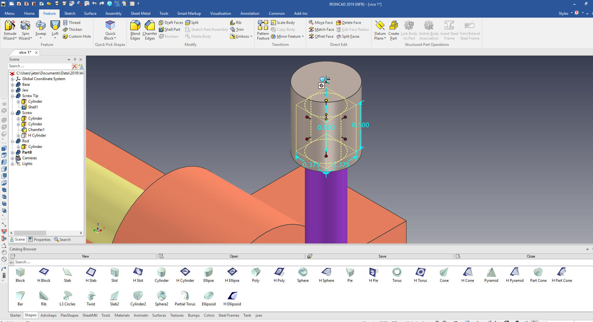
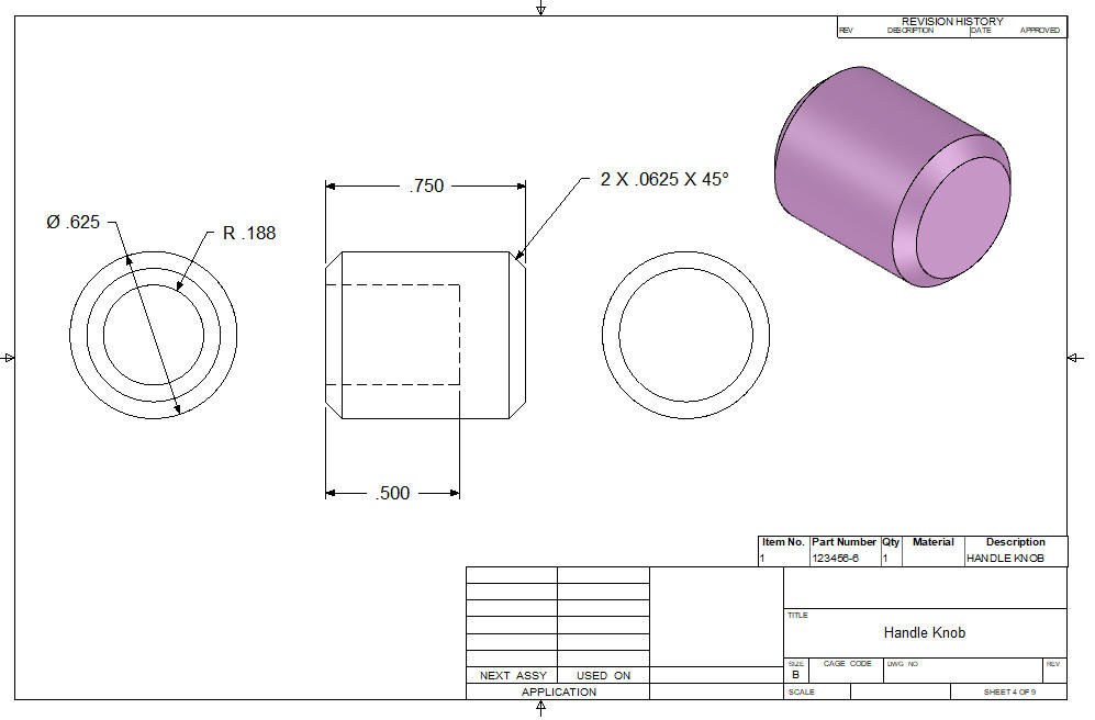
We
don't have to have any specific face available to create a hole. We
will just drag and drop a hole cylinder on the top of the Handle knob and
size from the other side.
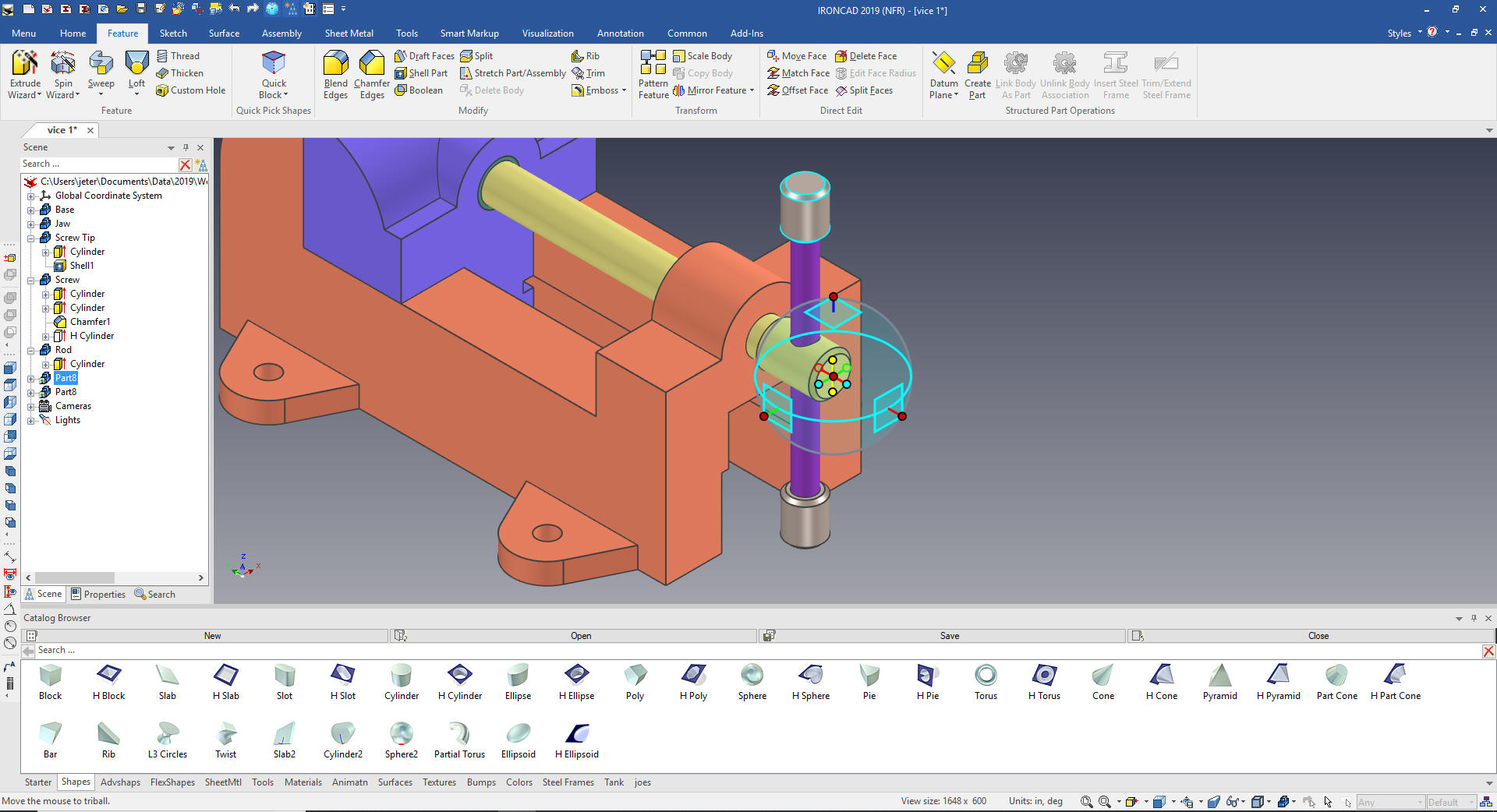
We add
the chamfers and using the Triball we mirror and link the Handle
Knob.
I will
change the name and color of the Handle Knob since they are linked
both parts change. And since we are done with the catalog I will set
to autohide!
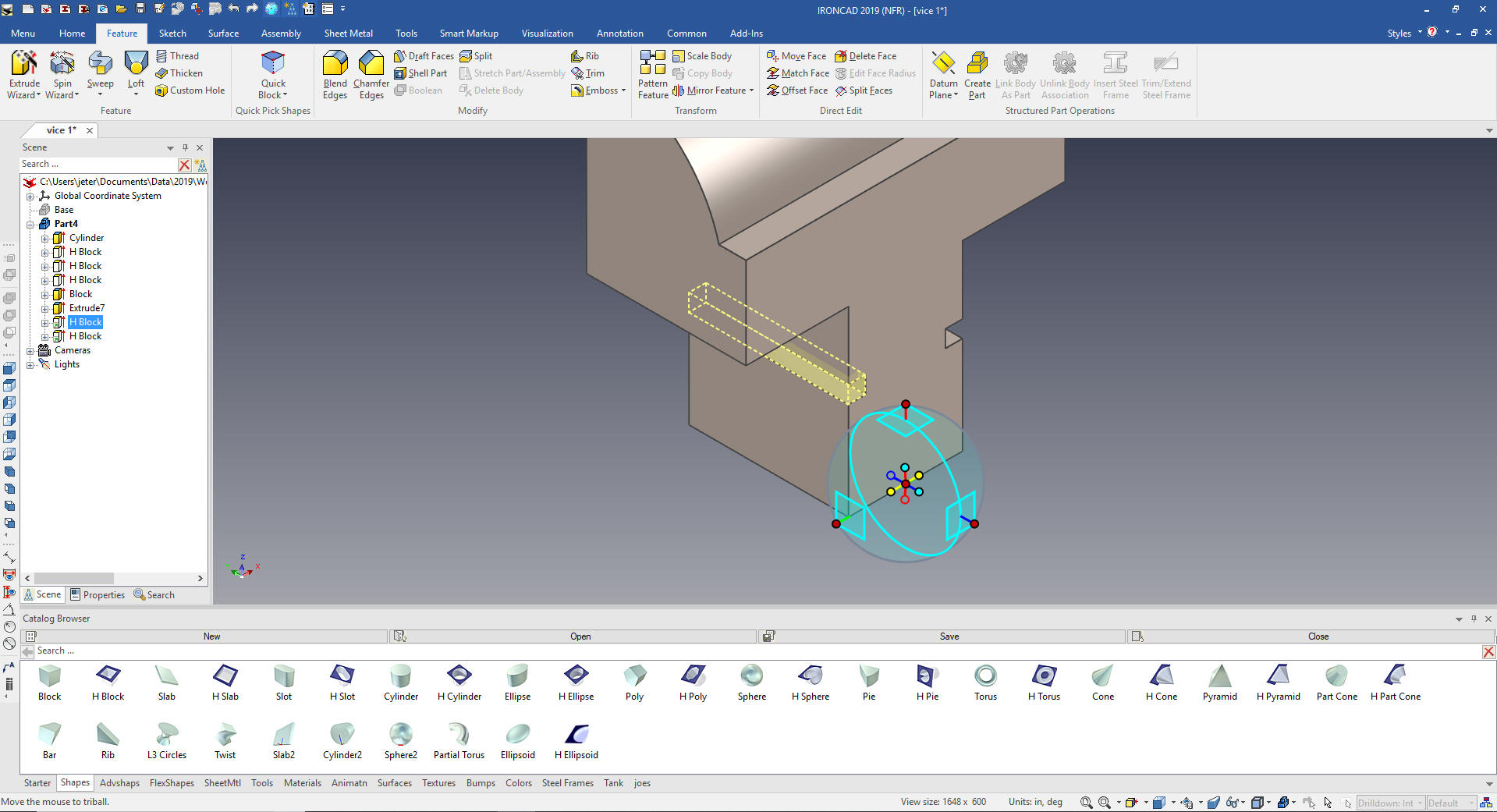
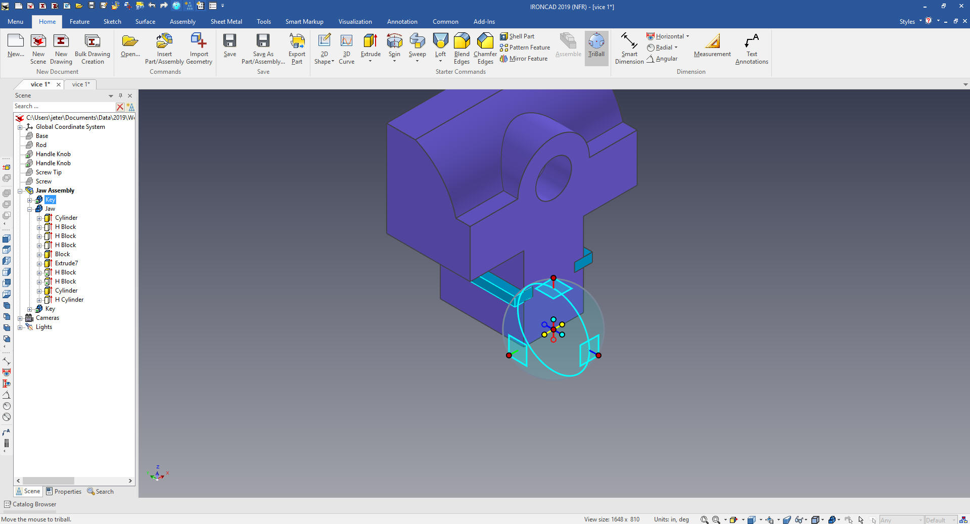
Darn
it I forgot the Keys! No problem. We just hide all except the jaw.
Drag and drop a block, again with the right button to create a new
part onto the face of the jaw. Size using the geometry of the jaw.
We mirror link using the Triball and now we are done. Of course we
change the name of he part in the scene browser and the color.
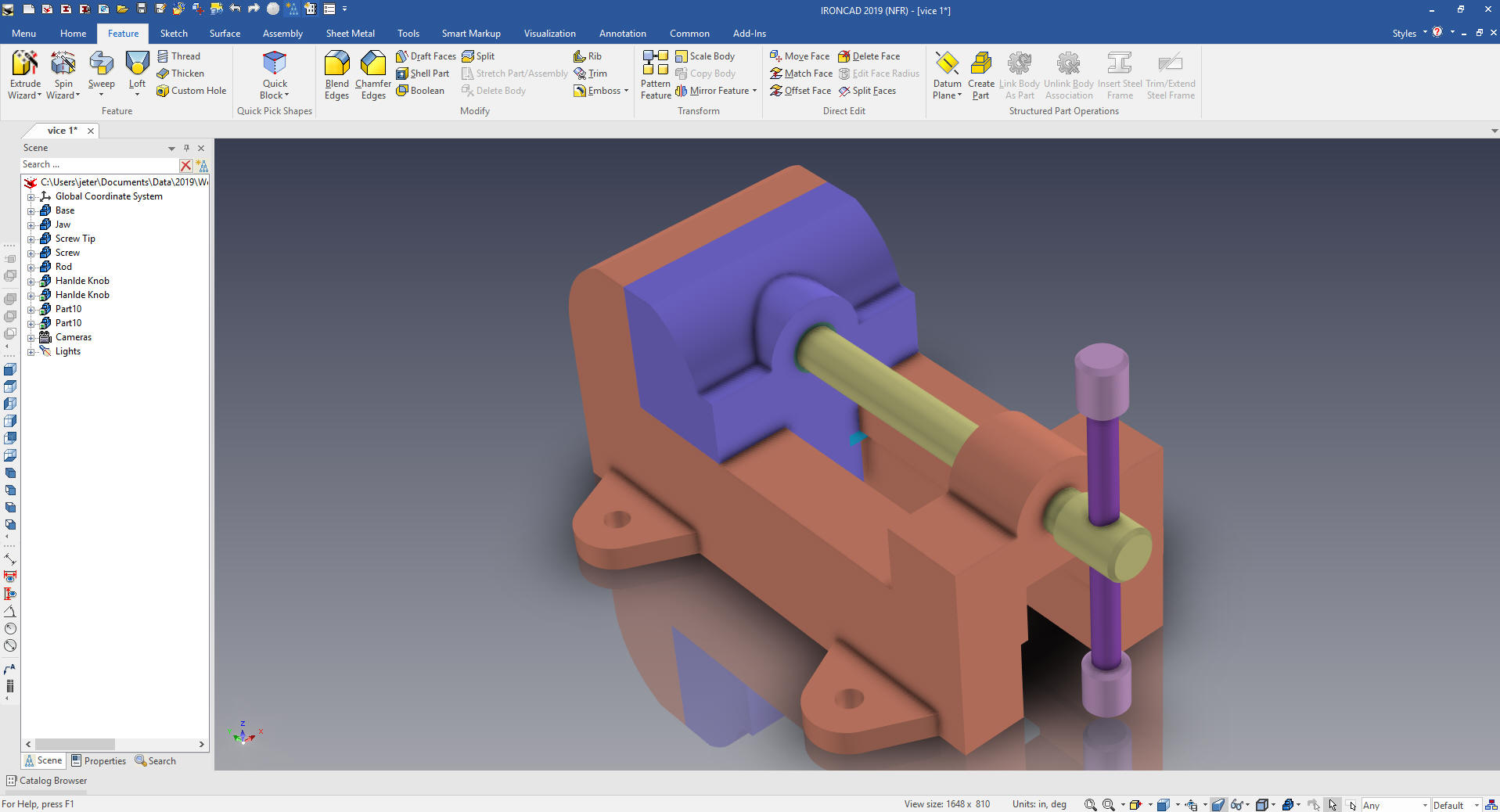
There
you go, done in one file, top down and in context!!
You
cannot deny the increased productivity!
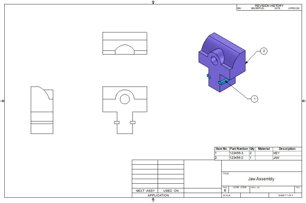
We
only have one Jaw assembly the others are assembled at installation.
Assemblies are created by selecting the parts and select assembly
from the dialog box. You can have any number of iterations of the
design. Sometimes I create an archive to move the older iteration
assemblies for reference later.
Making the drawings is a breeze. We just select the Bulk Drawing
creation, select the parts and IronCAD will generate the assemblies
and the other 7 parts for detailing.
It is
very important that you look into how you or your engineers are
creating the parts. Streamline Sketching and Feature Based Modeling
is easy to learn and implement. It, alone, will increase
productivity 10X. Now, IronCAD with its unique integrated
history/direct edit functionality can increase your productivity
another 5X or more with changes! Again, time is money in
engineering.
More on StreamLined Sketching and Feature
Based Modeling.
To experience this increased level of productivity, please download
IronCAD for a 30 day evaluation. Legacy data is no problem, IronCAD
can read the native files of all of the popular programs. IronCAD is
a great replacement for the subscription only Autodesk and PTC
products.
Give me a call if you have any
questions. I can set up a skype or gotomeeting to show this part
or answer any of your questions on the operation of IronCAD. It
truly is the very best conceptual 3D CAD system.