|
Learning IronCAD! Lesson 2 Drag and Drop Design Designing with Shapes 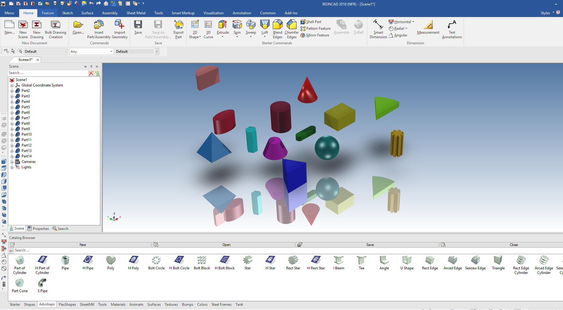 |
|
Note: IronCAD is
such a innovative 3D CAD system that I have to give a brief description
of the basic 3D modeling philosophy and a bit of history as compared to
the major history only CAD systems based on strict constrained
sketching, what I fondly call the Solidworks Clones. If you are already
an IronCAD user or are aware of these differences please continue to the
training segment of the article.
Lesson 3: Streamlined
Sketching in IronCAD!If you would like to join in: For more information or to download IronCAD This is a 30 day fully functional IronCAD evaluation including the Translators for all of the popular programs. Go ahead and import parts and/or assemblies. You can actually modify the parts faster than in the original system. Please start with the first lesson since they go in order of how you use IronCAD and introduces you the incredible highly productive flexibility. Learning IronCAD! Lesson 1 Setting up the Scene (Workspace) Today we are going to explore drag and drop solid modeling, what I like to call: Design with Shapes. We open IronCAD. This screen is optional. I recommend using it since It offers a selection of options from recent files to creating new files. In the lower left corner we will deselect the "Use default templates" If you commonly use the default scene you can set it for the default. 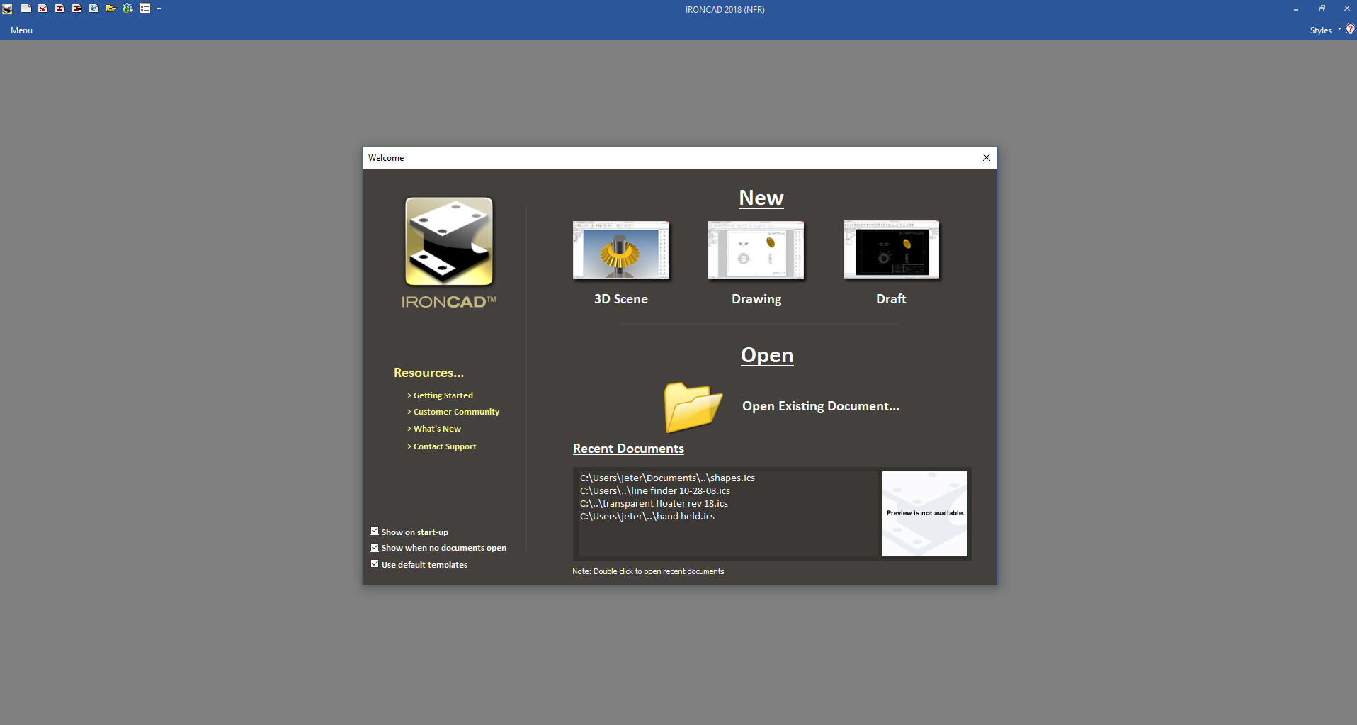 We will create a new 3D Scene. We now can select a custom scene. You can just click okay and it will open the default scene. Please review lesson one on creating custom scenes. 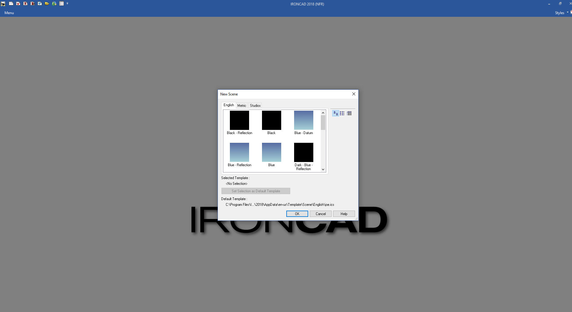 We are not quite ready to work with shapes. With IronCAD you have 3 design options available to you: Drag and Drop, Sketching and Direct Edit. The catalog is not always needed as you do design so we auto hide it for more scene or work space. 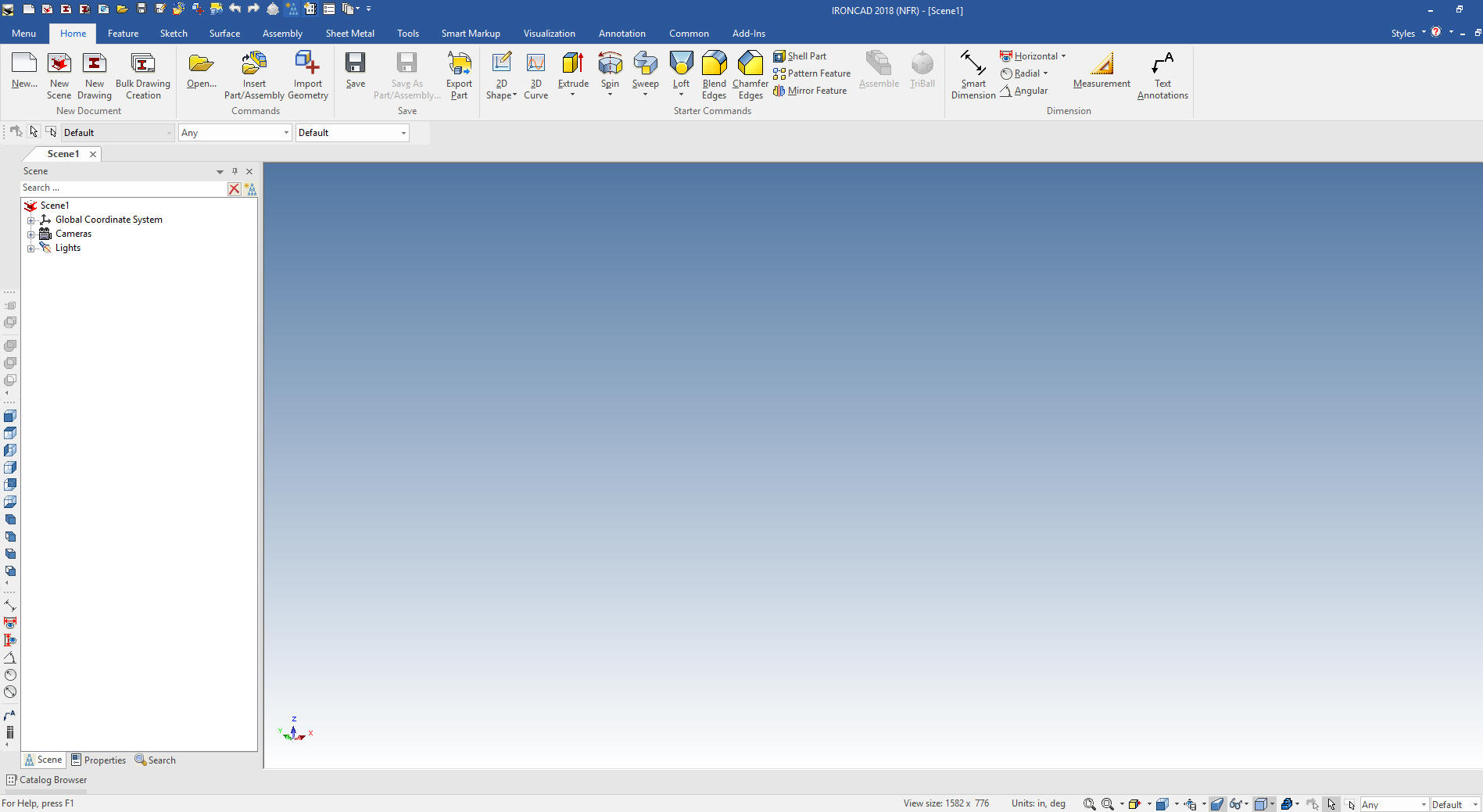 To bring up the catalog we left mouse click on the "Catalog Browse" in the lower left. We then left mouse click on the pin on the right side of the catalog to lock it in place. We will select the shape category. 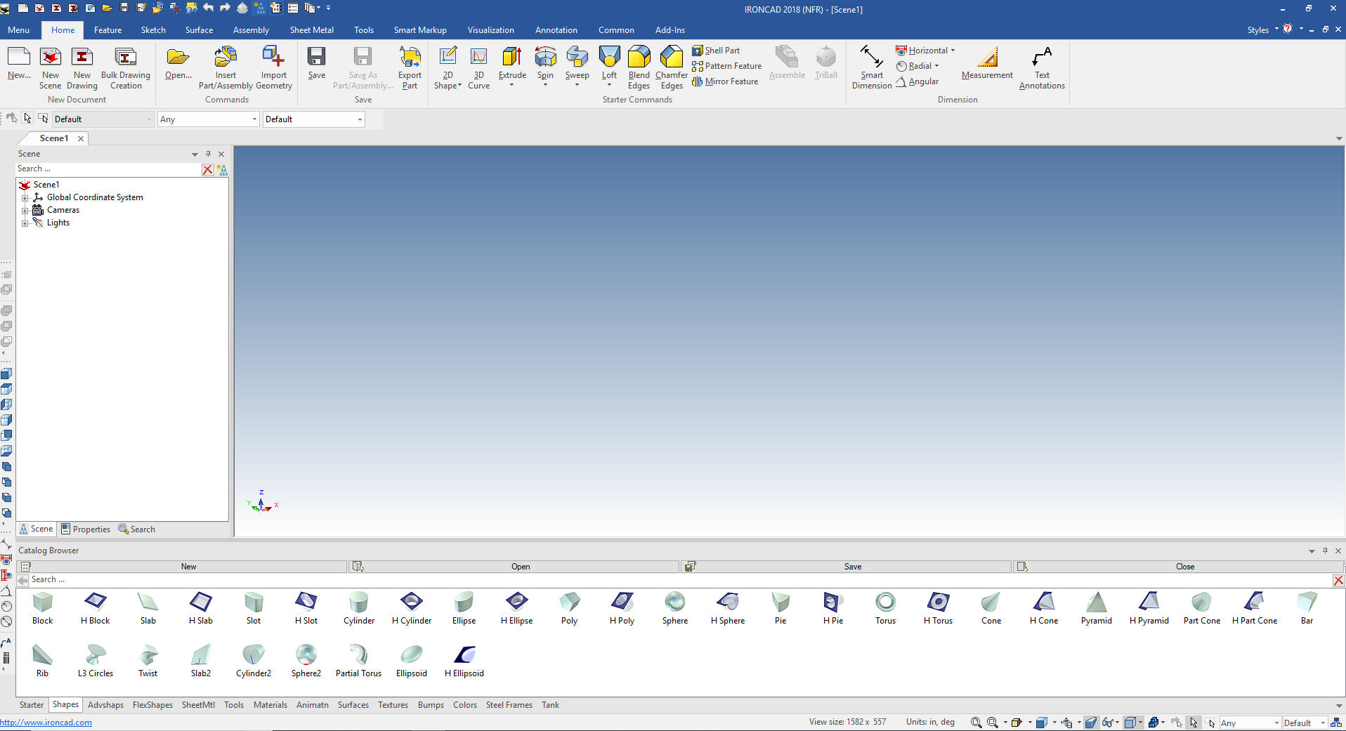 We can then start dragging and dropping shape into the scene. As you do this make sure you drop them into a free space on the scene, I will explain why later. We just want to see how easy it is to drag and drop them from the catalog. Notice on the left that with each shape dropped into the scene a new part is made. IronCAD is a single model environment which means parts, sub-assembly coexist in a single 3D space. We can have many different iterations of parts and assemblies in one file. 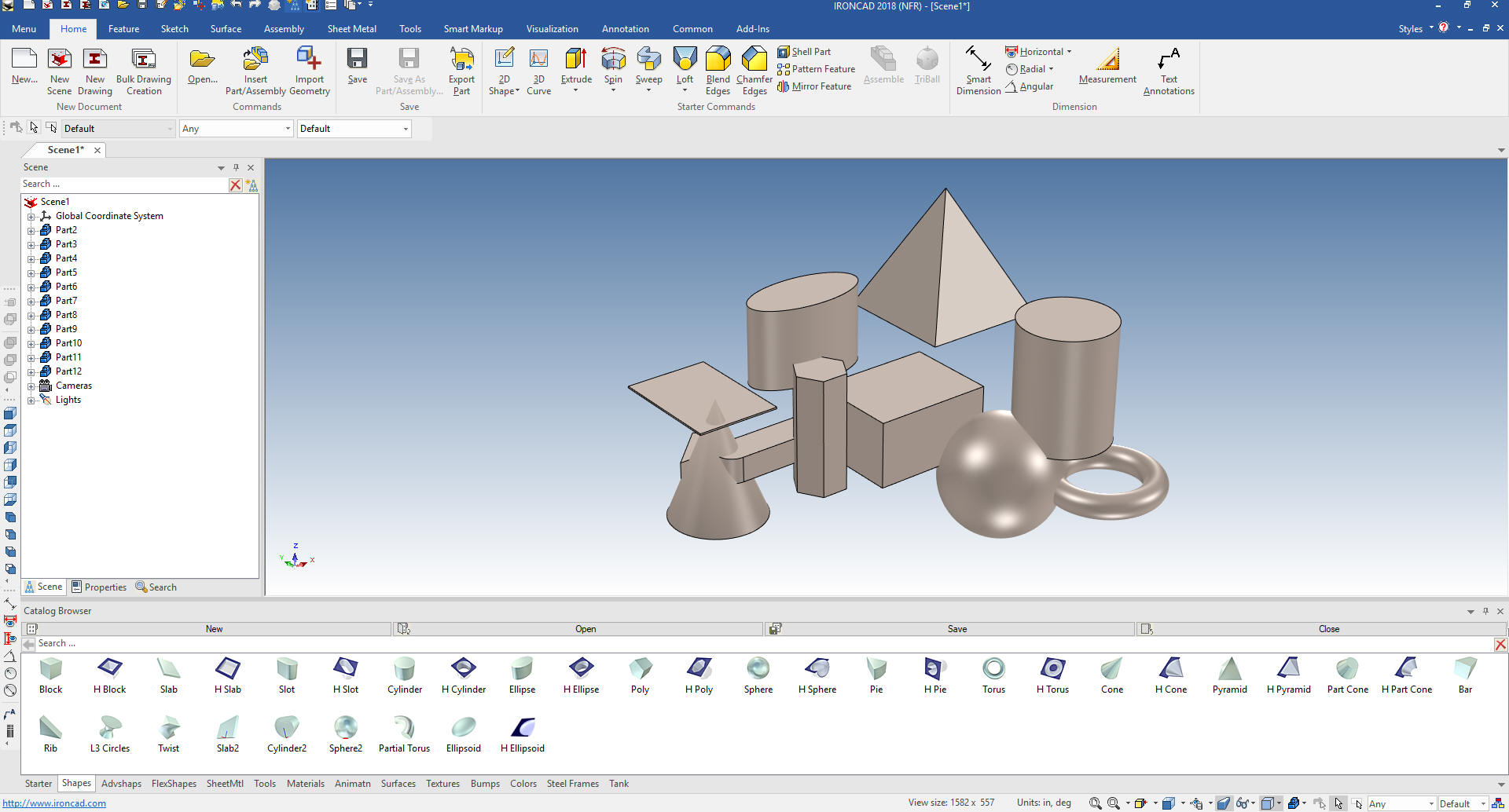 IronCAD calls these shapes "Intellishapes" The are all based on sketches. Lets open a new file by left mouse clicking on the menu and hovering over file and a dialog box with come up and we select "New Scene" which will automatically bring up a new scene. You can now see Scene 1 and Scene 2 Lets drag a block into the current Scene 2. You can see part2 highlighted in the scene browser. With a double click you can rename the part. I will rename it to Block One. You can also see the "block" feature that his part is made of. 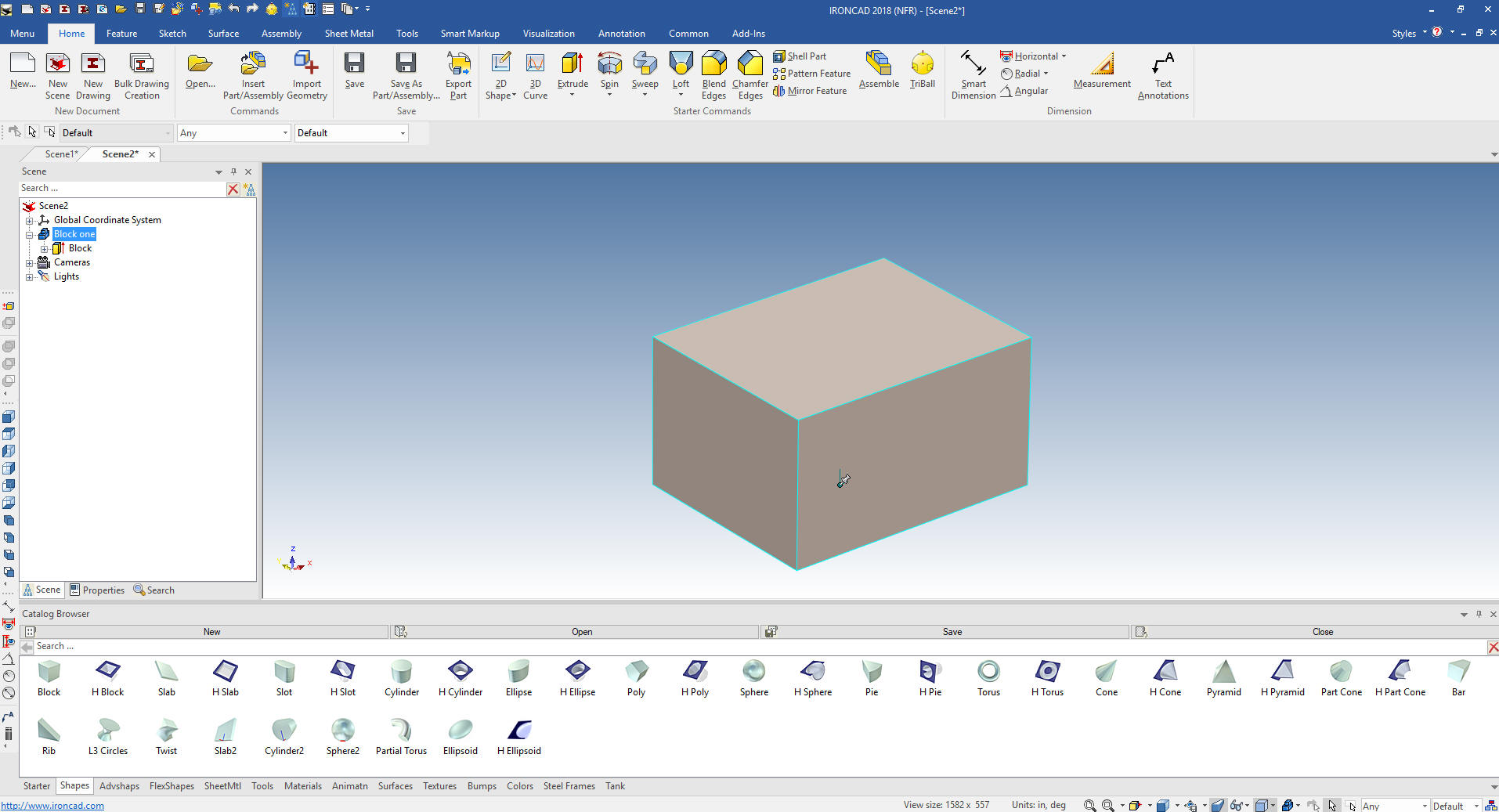 We have levels of access in IronCAD. Assembly is yellow, part is blue, shape is yellow and face is green. Above you can see the blue highlighted edges will will again select the block and it will activate the intellishape. 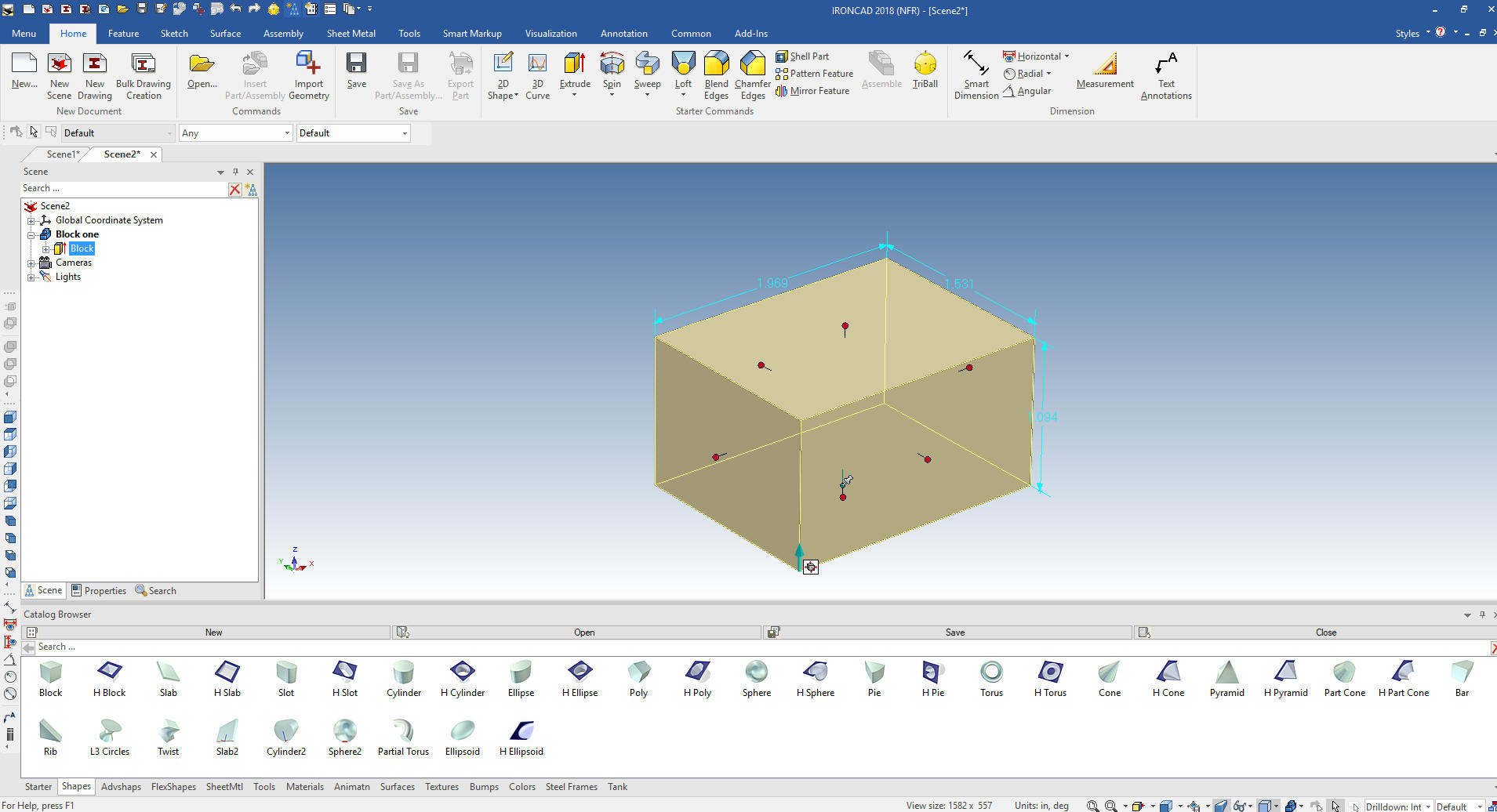 I am showing this to show there is much more to drag and drop than first meets the eye. There is an incredible level of sophistication in these Intellishapes. As you can see we have handles we can push and pull the adjust the size of the feature. But if we click on one of the handles a dialog box comes up. 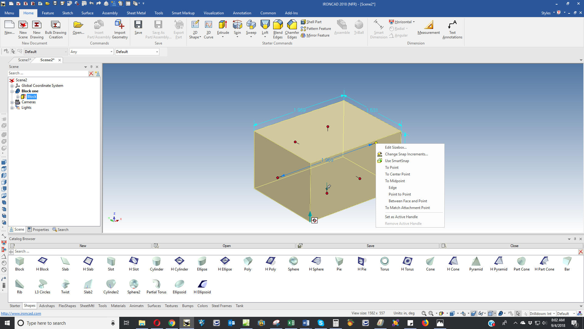 This dialog box offers many options to manipulate this intellishape. 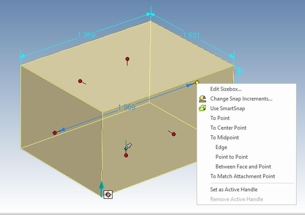 But it offers even more flexibility. We go to the feature level right click the shape and a dialog box will come up. Select "Edit Cross-Section 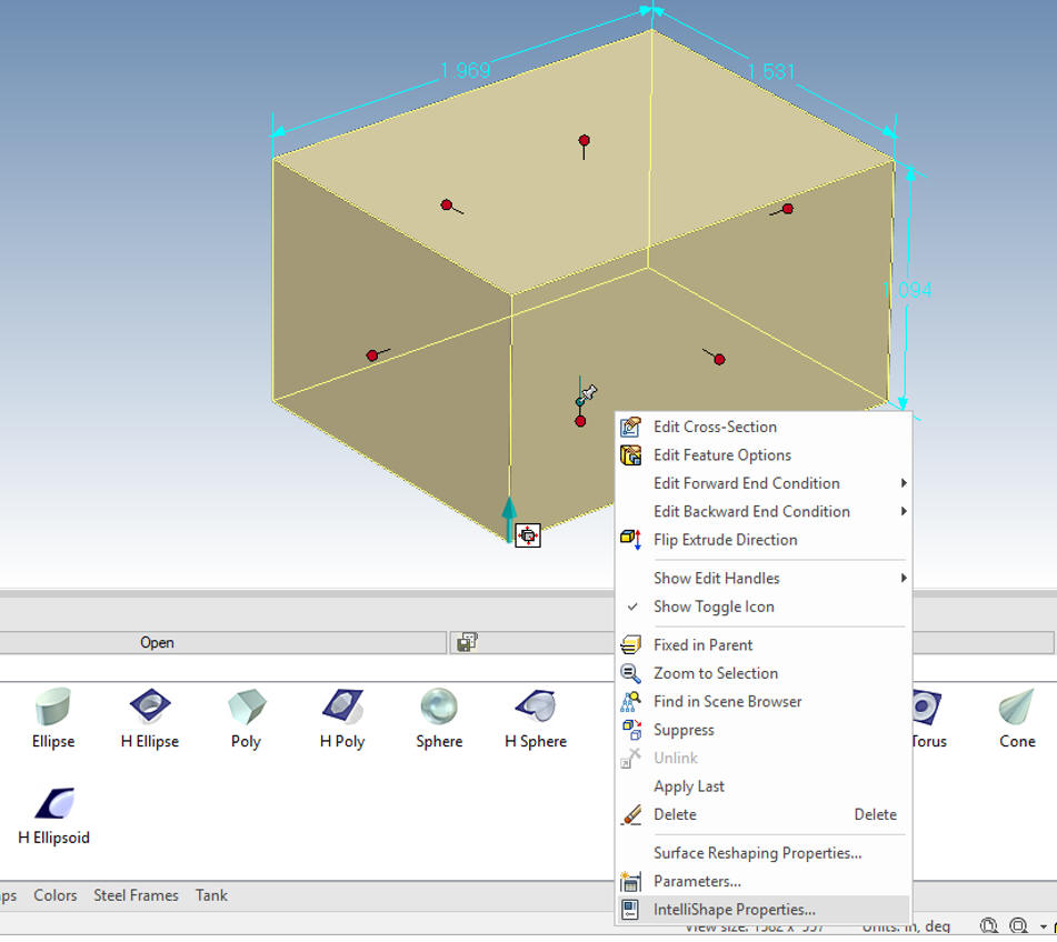 You can see the rectangle on a grid that makes up this block. This is a sketch and can be altered but it must be able to create a shape not having any curves crossing over each other. Sketching is not part of this lesson. I just wanted to explain the sophistication of the intellishape and how it is different from the limited primitive shapes of other programs. 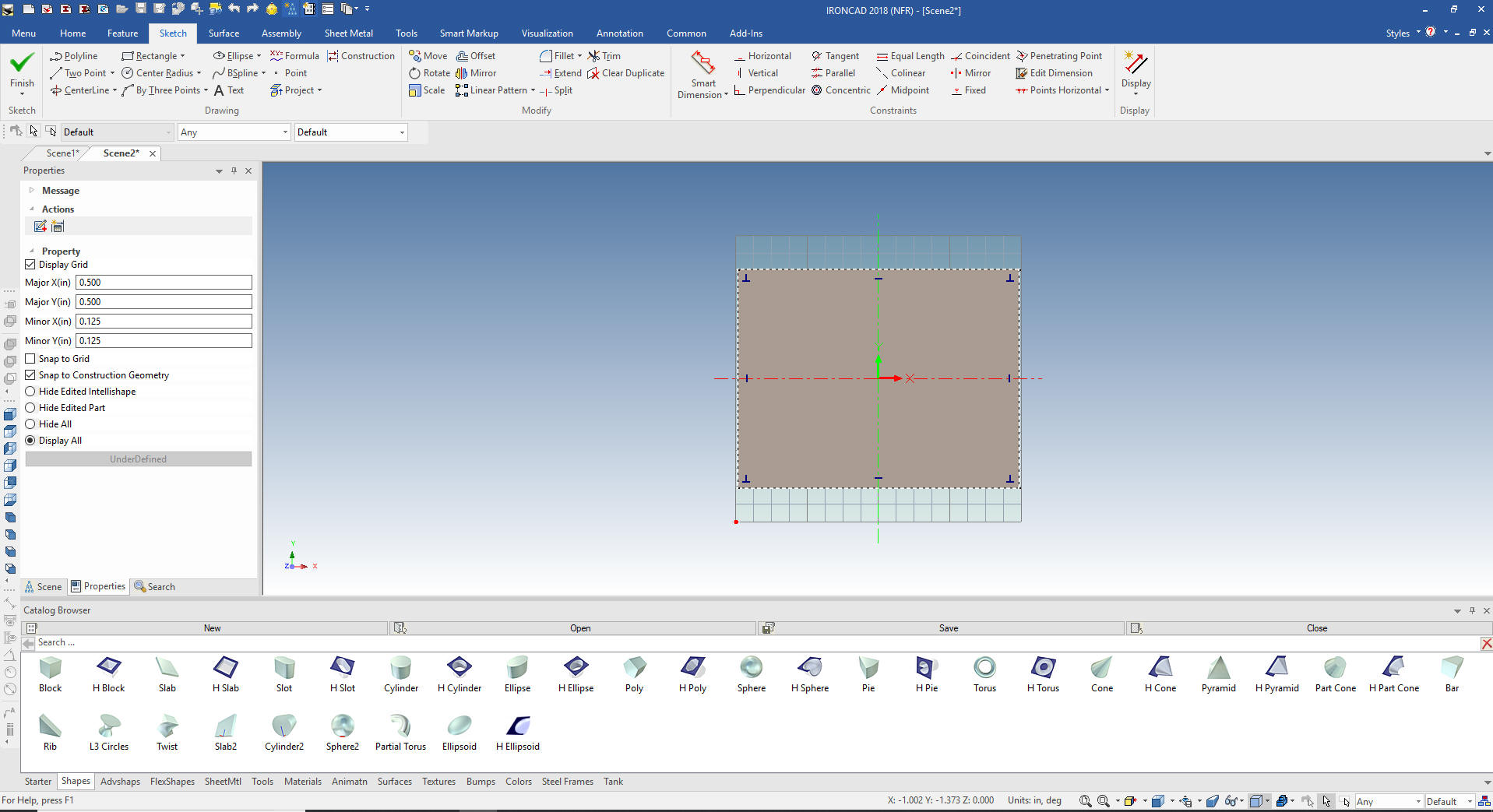 Here is the iso view showing the position of the sketch. We also can edit the height of the block. You can play with the other shapes and their sketches and options, each have enough options to control their shape. 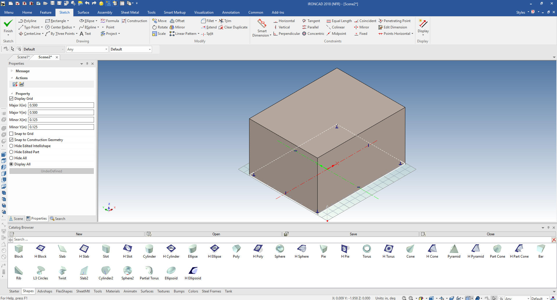 I will set the block to 2x1.5x1 and drop a hole block on the top. If I hold the shift key down while holding a handle I can snap to a faces, edges, corners or mid-points I pull the front and side handle to the relative faces. I will then select the affect handle and set them to 1x1.5x25 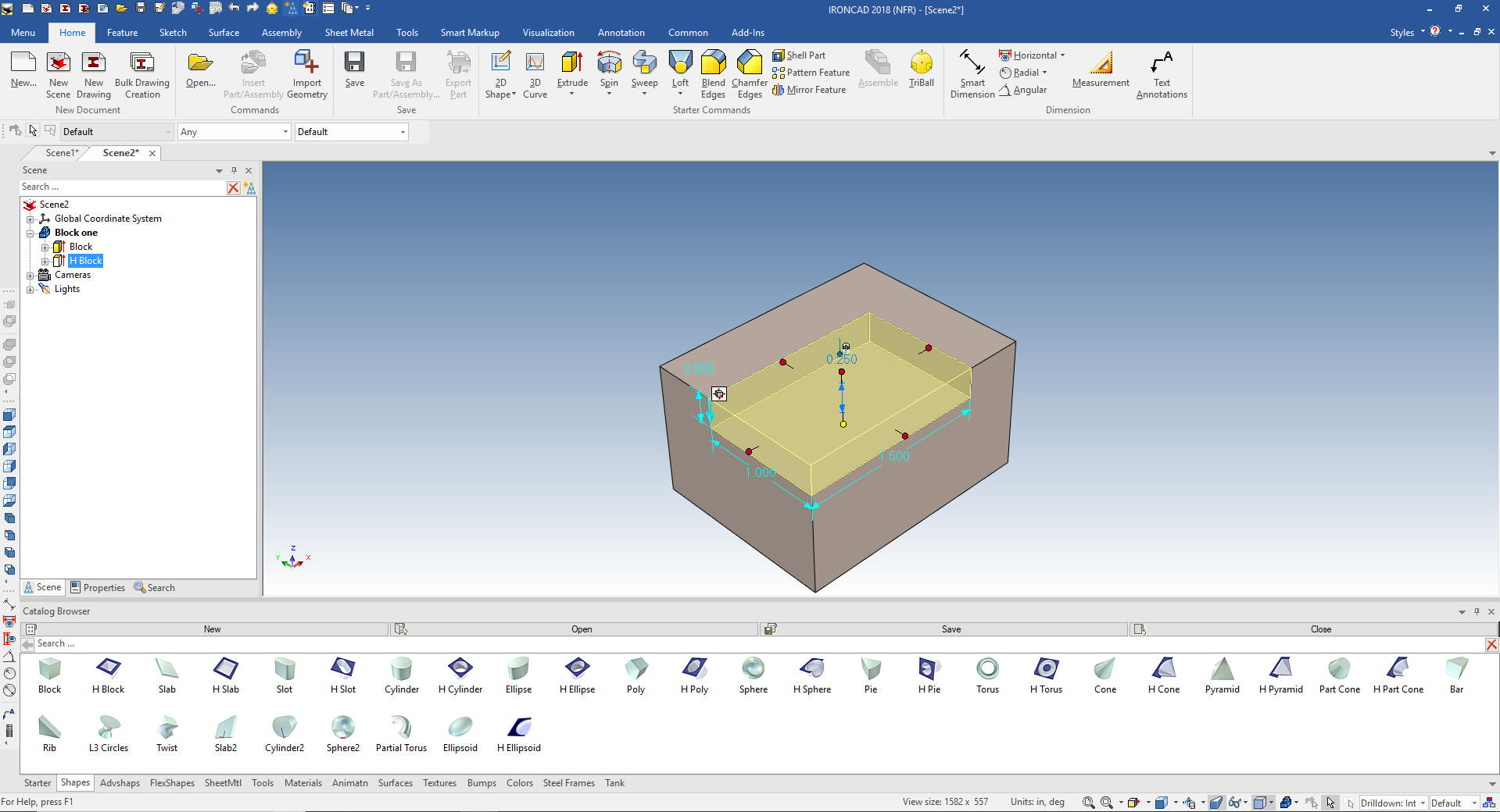 This is hardly rocket science. You can see how simple design can be. No constrained sketching, no inserting parts, no complex history just working with shapes. I will bring up another file showing many shapes. You can set the color by selecting at the part level and going to smart paint, another hold over from the graphic design days of Trispectives. We have also added some rendering effects. Both realistic rendering and animation are an integrated part of IronCAD. 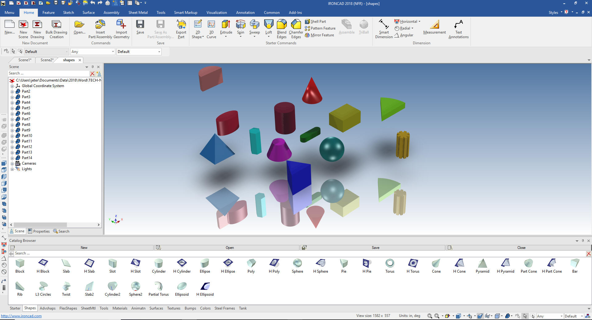 Working in IronCAD While dragging and dropping shapes from the catalog is fun we sooner or later have to go to work. We will convert a drawing to 3D. This is by far the best way to learn a CAD system. We will take this simple part an create it with drag and drop with a fillet or two.  We can see that this part is made up of a rectangle 3.125x1.5x1.5 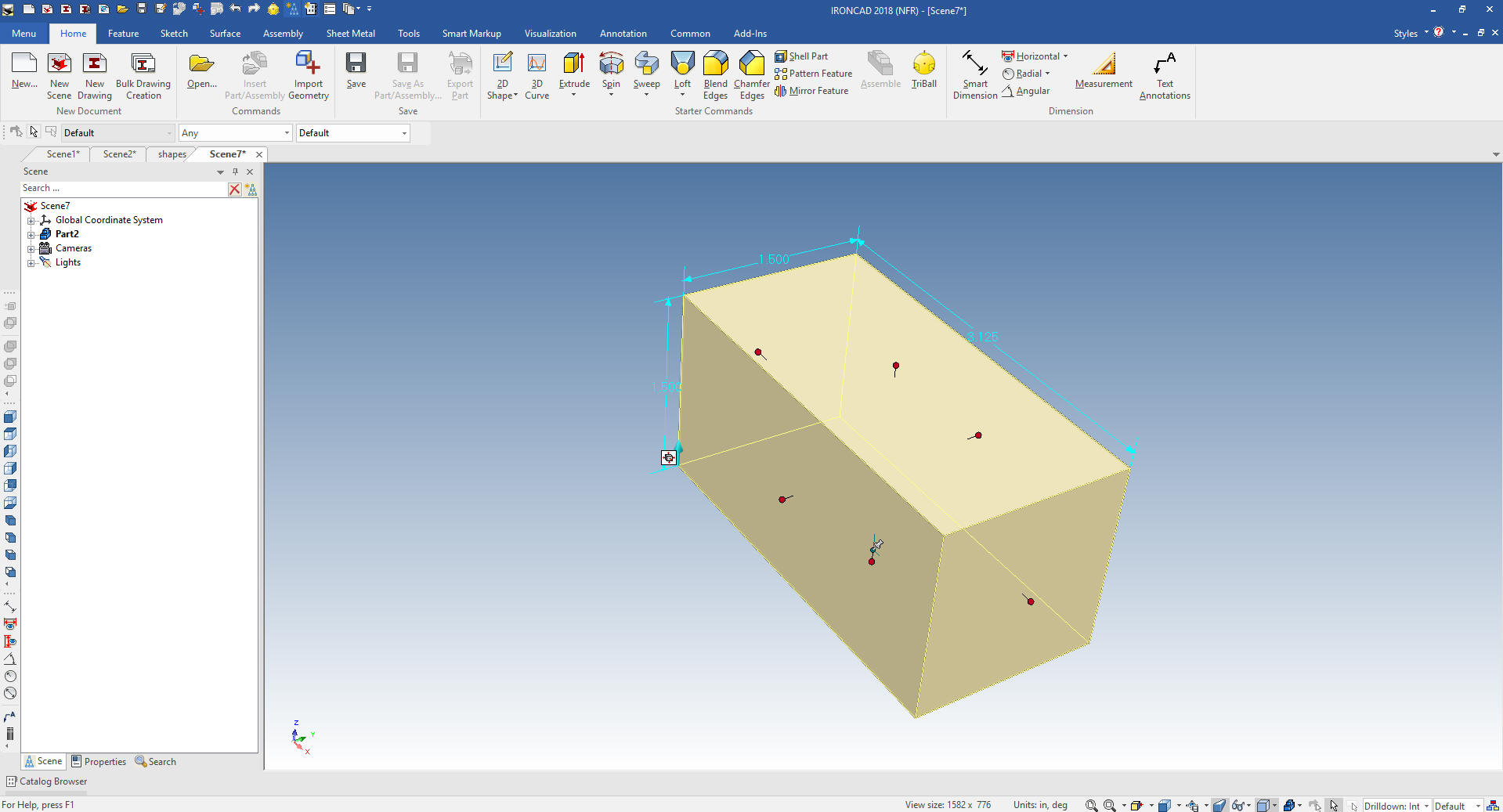 Now we add the two fillets. 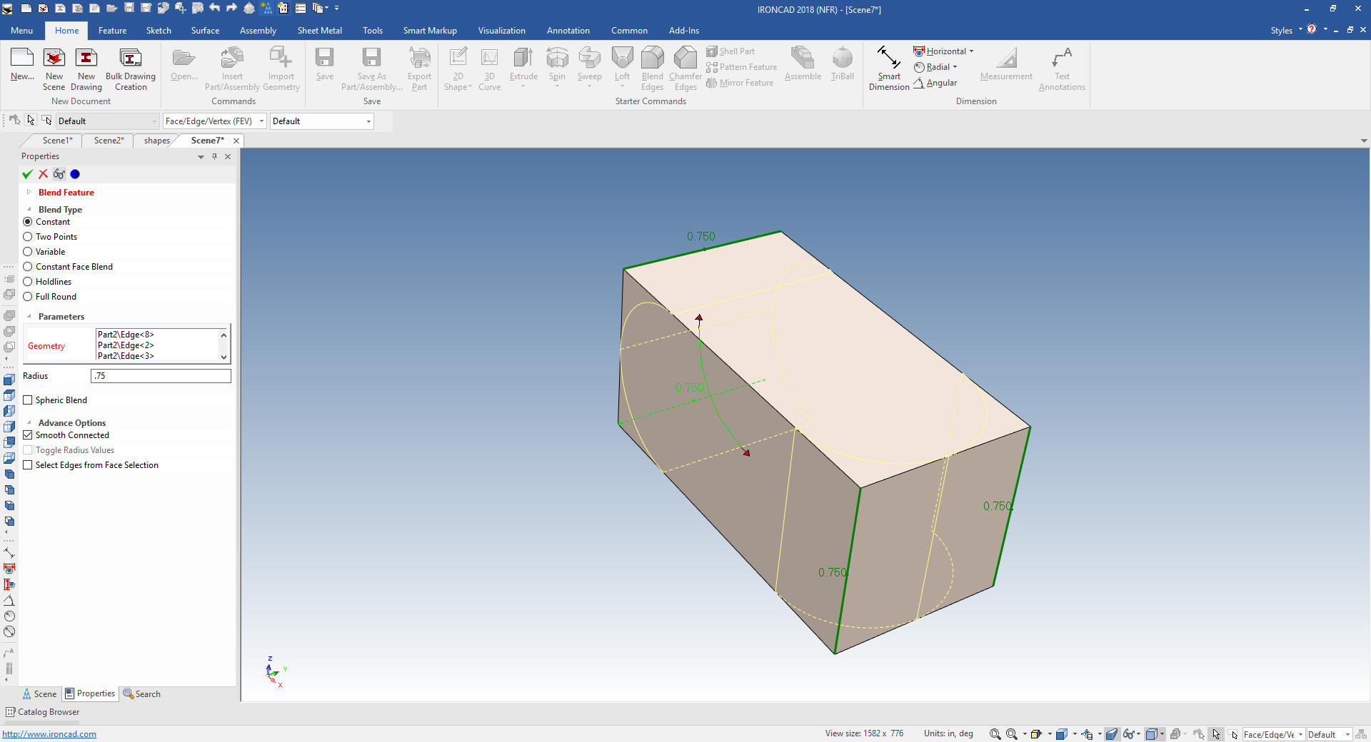 We now add the slot. We drop a hole block on the top of the shape and pull it into location and size it. You get used to using different feature to locate the feature. Very simple. I don't want you to forget we can do sketching using the extrude wizard but I will get into that in the next lesson.  Now for the holes. We drag a hole cylinder to the top face using the center of the blend as the location and the same with the side hole. Set them to the correct diameter and assure they go through and we are done. Fun, no hassle design. 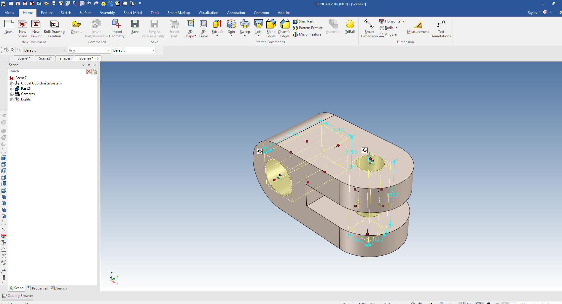 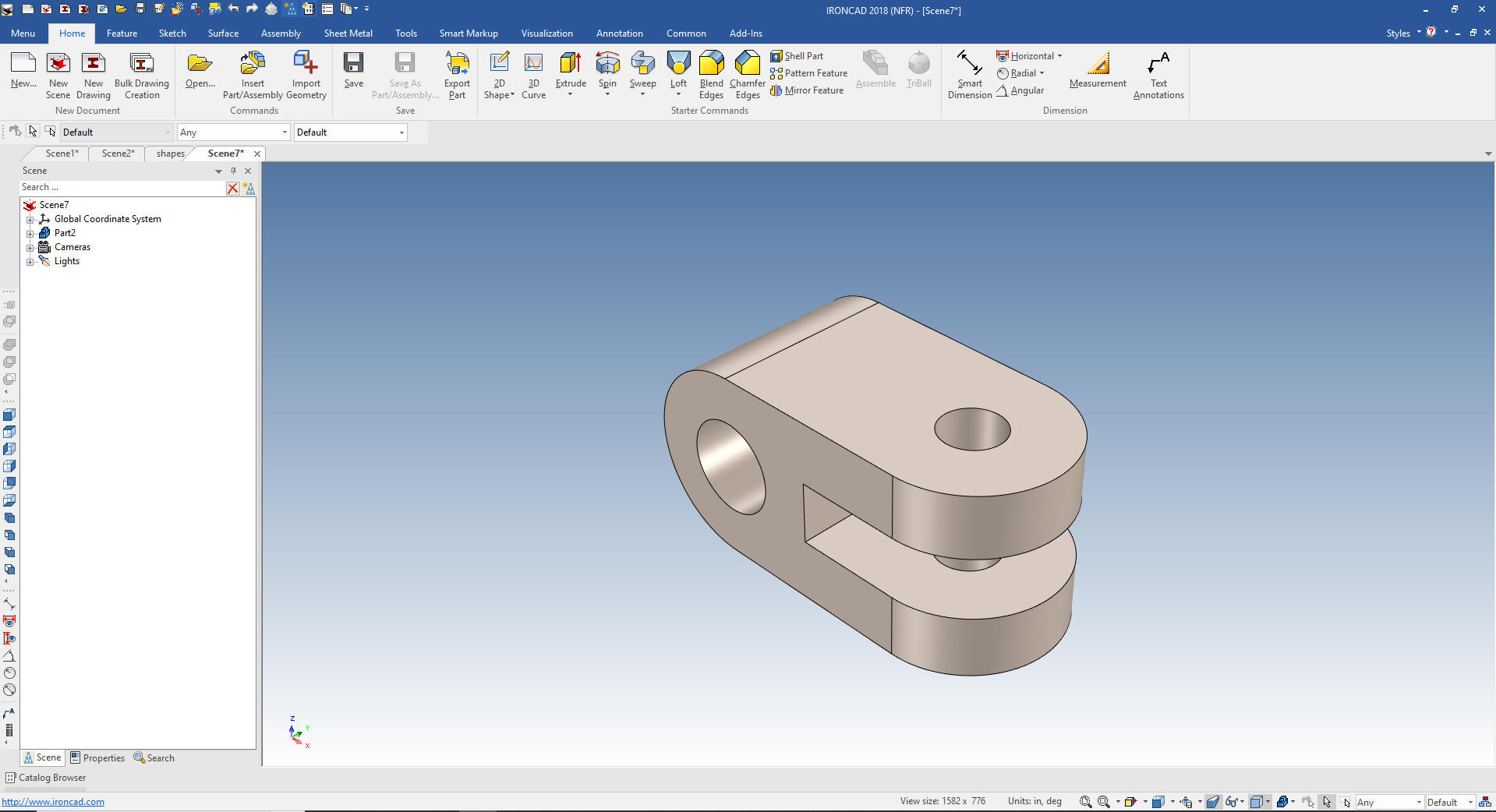 We will do another.  We bring up a new file. But we have to go to the common menu an set the units to millimeter. 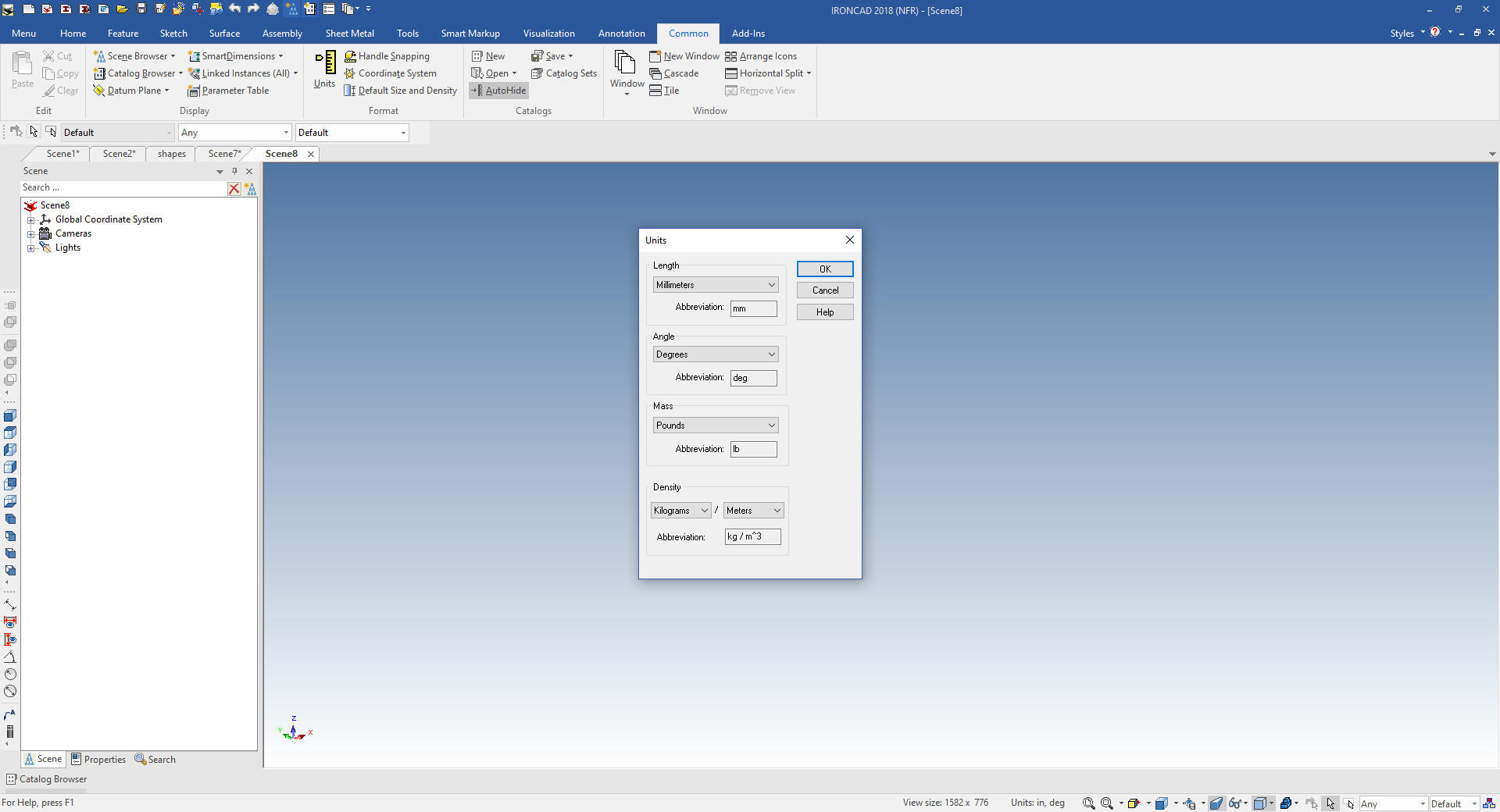 The first thing we notice is there is a rectangle we can create. Designing with shapes is different than with sketches. While you can do equal design with sketches you think in a different way. I have seen this part made with sketches and it is quite time consuming. Even though the modeler could have used the shape concept, you have to step out of the box. So we will create the first rectangle. 47x26x30. 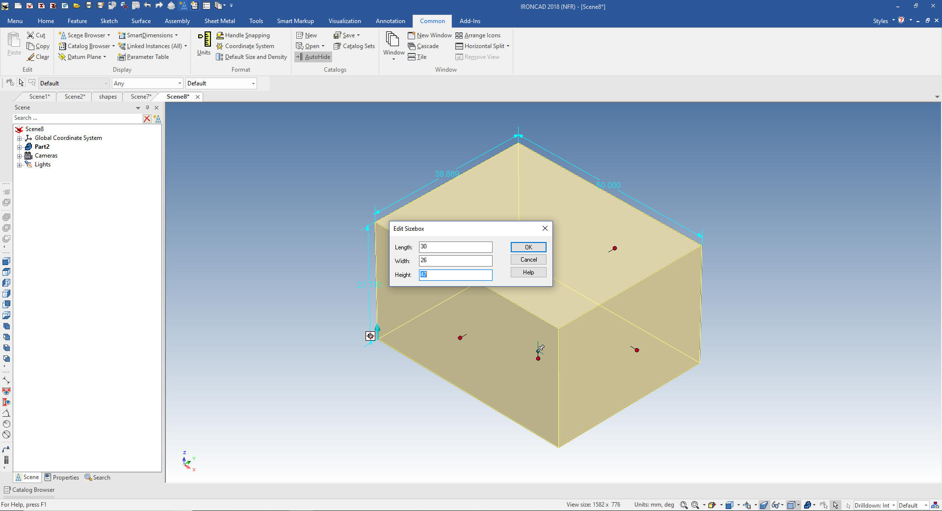 Then we will add the blends. 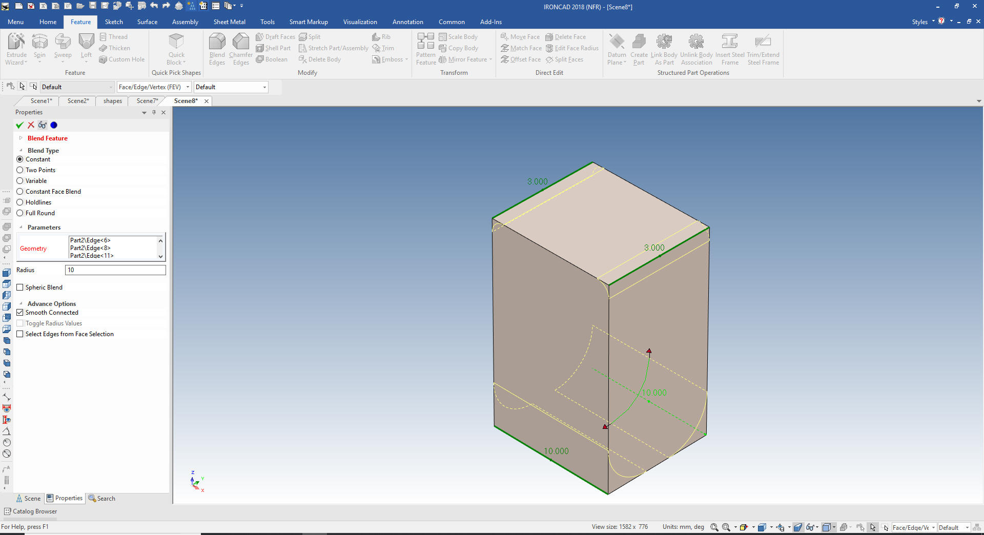 I have coined shape design feature base modeling. Since we are only design with drag and drop we now just shell the feature 5 mm. 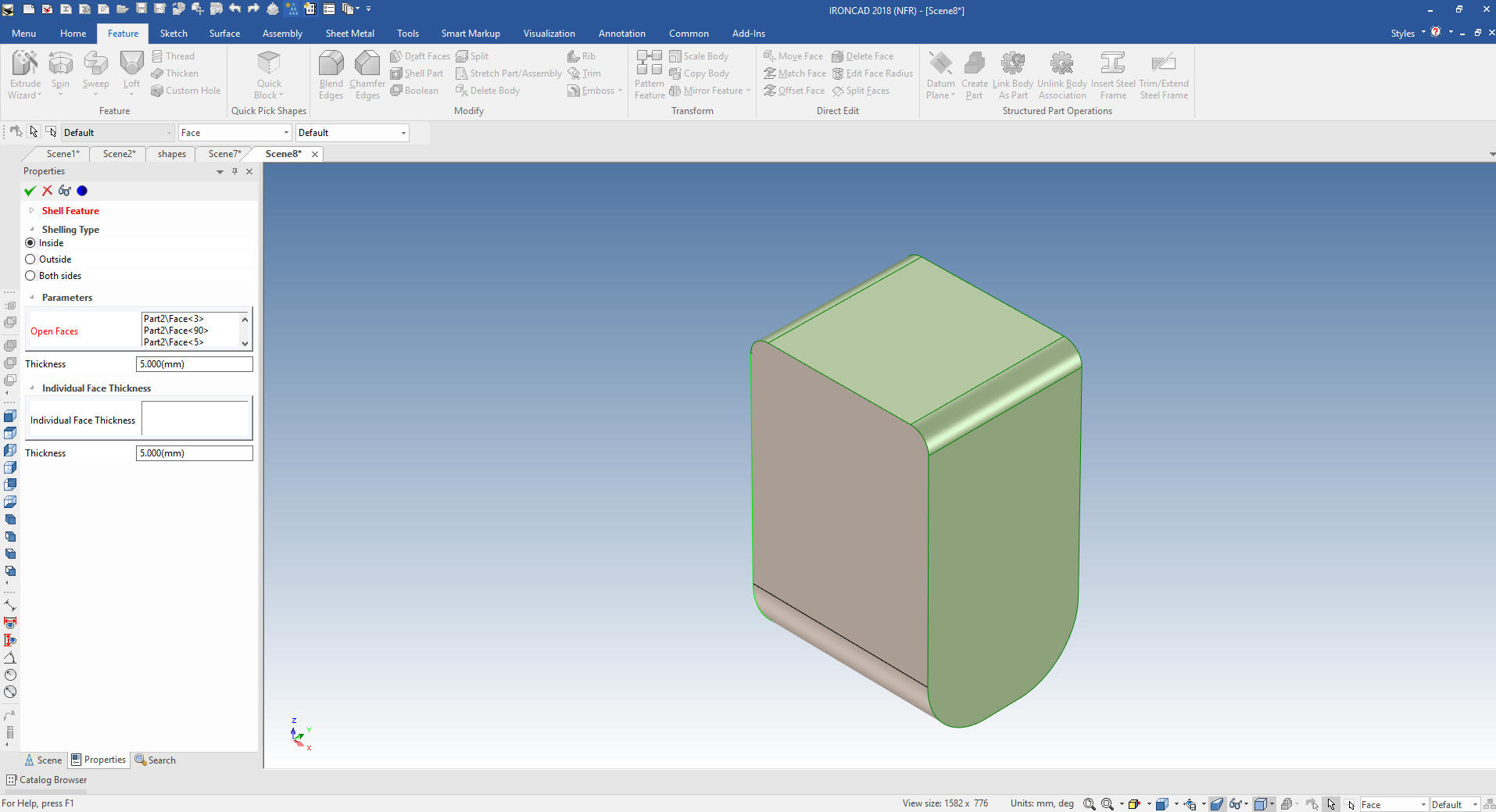 And we are done with the basic shape. Honestly how many of you would have thought of this. It is available in a sketching only system. 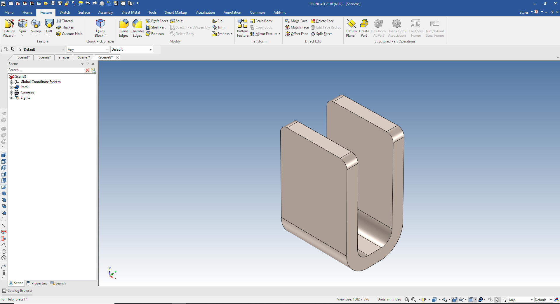 I will create the hole later. But now we have the base. I drag and drop a slot shape onto the front face using the right mouse button then select "drop as part". This brings it in the correct orientation as a new part. I will size it to 70x16x6.3 I will change the color by right clicking on the part level and selecting smart paint. 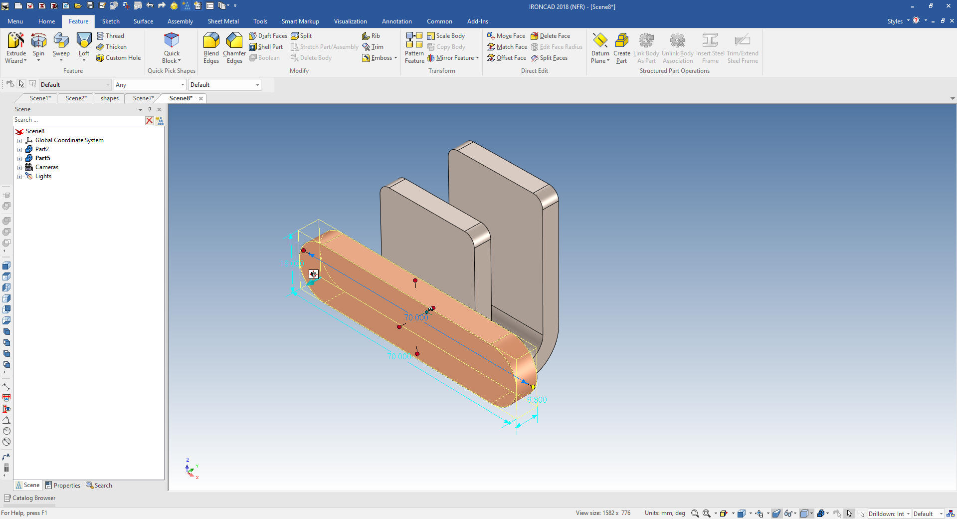 Now I am going to introduce you to the Triball. This is IronCAD's feature, part, assembly manipulator. We are going to turn on the Triball, push the spacebar that allows you to locate the Triball and located it on the mid-point of the top face of the base shape. I will again push the spacebar to now allow the part to be moved. 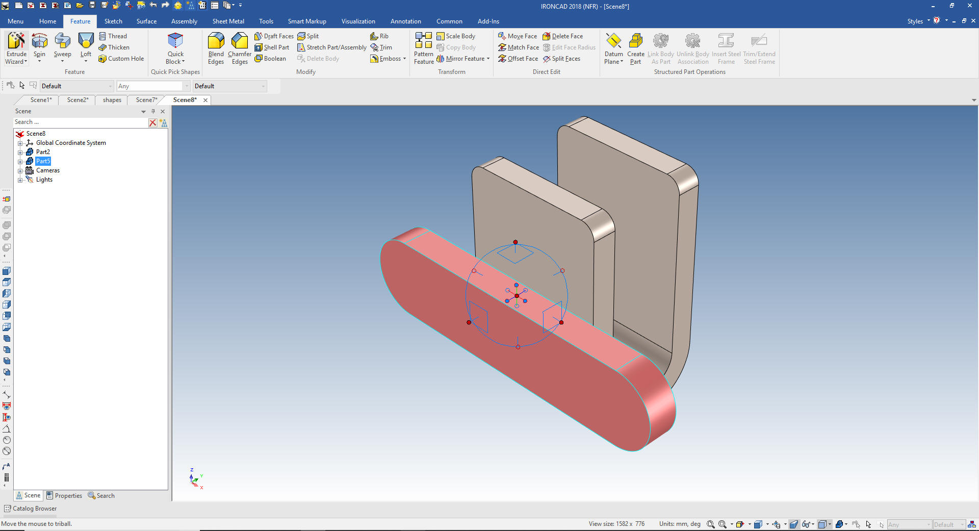 We now rotate the view, looking at the bottom of the channel. We will move the base to the mid-point on the bottom of the channel. Notice we move to different locations without putting in specific dimensions or locations. We can do this much of the time but other times we do have to explicitly locate a feature. 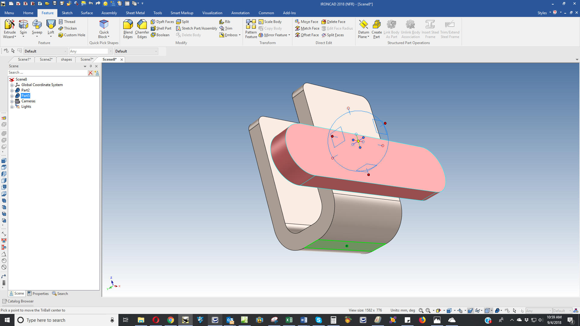 Now we move to all we have to do is add the holes. 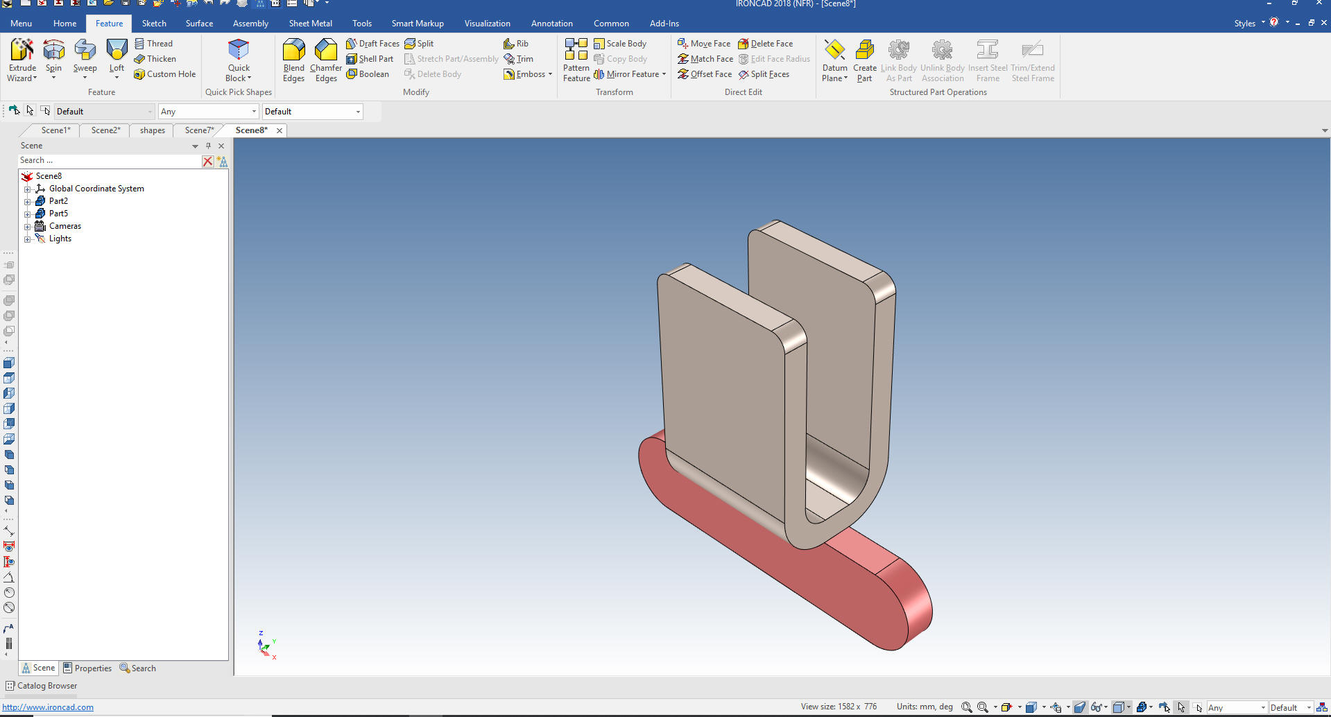 Adding the holes is easy. I drag a hole cylinder to the center of one of the fillets. I want these holes to be linked so after I create the first hole. I will use the Triball and create a linked copy at the center of the other fillet. Note: The Triball is used in a variety of ways. If you have a dozen fasteners you would locate them with the link copy feature and this would handle the fasteners as one item in the parts list. 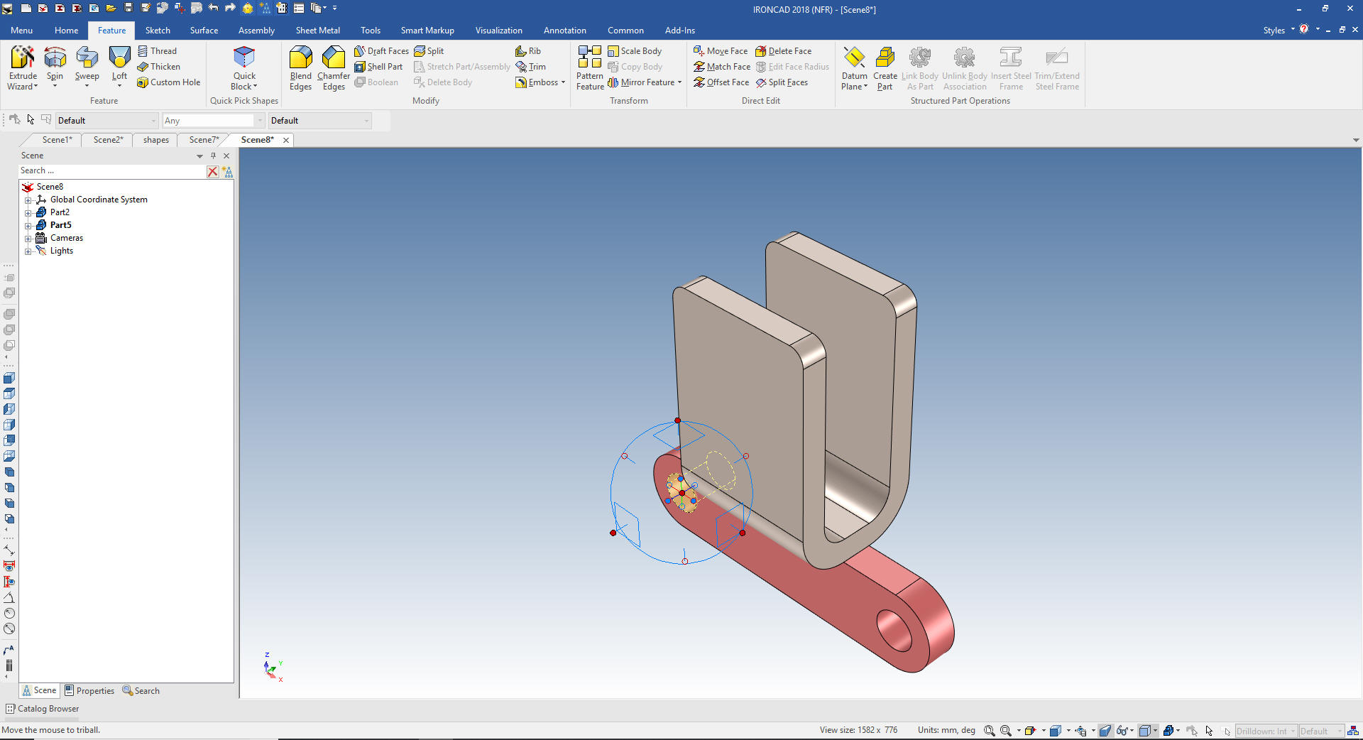 The top hole is a bit different. We drag a hole cylinder to mid-point of the face and set the diameter 4mm making sure it goes through the part. We then turn on Triball and locate it from center of the bottom holes.  Again notice we have two parts in this file. The single model environment is by far the most productive 3D modeling system feature. There are only 3 systems I know of that have this feature and two are direct edit only and the other is Solidworks Conceptual. I have tried to get an evaluation copy, but you have to call. Then pricing it at $2988.00 per year makes it quite unattractive since you can rent IronCAD for $1,500 and buy it out right for $3970.00. Again please download IronCAD and start comparing the increased productivity. Today, engineering is a bottle neck due to the time consuming design paradigm of the major 3D CAD system. IronCAD can increase productivity on conceptual design 5X and with modifications 10X. This translates to real cost savings. Is 3D CAD Productivity an Oxymoron? For more information or to download IronCAD Here are some exercises that you can do. Most are drag and drop. The next lesson will be on IronCAD streamlined sketching. IronCAD vs Fusion 360 IronCAD vs Solidworks Again If you have questions please skype me. I am usually available from 4 am to 2 pm weekdays. Weekends usually from 4 am to 10 am. Maybe later, if I have some work, you can always give it a try. Again please send me an email so I know who you are: joe@tecnetinc.com |
|
In the 1990's the only solid modeling systems at the time were completely based on sketching! You could only create a solid by extruding, revolving, sweeping or lofting from a sketch. The Pro/e constrained sketch design was copied by Solidworks. Solidworks added absolutely no innovation. Dassault purchased Solidworks and copied it for Catia 5. NX and Solid Edge were on the same path. This constrained sketching design was made the de facto standard with the development of Inventor by Autodesk. ZW3D, even though, sketch-based offer much more flexible design options by adding primitive shapes. Even CADKEY, a direct edit program was based on the sketch. Even though CADKEY had primitive shapes you could utilize. There was truly no innovation in the industry. Nothing but a bunch of Pro/e clones. Enter IronCAD Trispectives was released based on the ACIS solid modeling kernel in 1995. It was a graphic design package that designed by dragging and dropping "Intellishapes" from a catalog. It was very cleaver. I was a CADKEY dealer and FastSolids was release at the same time and also based on ACIS which made both packages compatible using the .sat ACIS Translation format. I quickly became a Trispectives dealer. Trispectives was sold to a OEM of Co-Create (Now Creo Direct). They incorporated history, sketching and direct edit and kept the drag and drop and named it IronCAD. I know, I know it wasn't my favorite name. LOL Now, IronCAD is the only solid modeling system that integrated history and direct edit modeling. Both are available in the design process. But this is beyond the scope of this lesson and will get into it in a later lesson that deals with direct editing. If you would like to join in: For more information or to download IronCAD This is a 30 day fully functional IronCAD evaluation including the Translators for all of the popular programs. Go ahead and import parts and/or assemblies. You can actually modify the parts faster than in the original system. Please start with lesson 1 Learning IronCAD! Lesson 1 Setting up the Scene (Workspace) I will be posting new lesson relatively often. If you are interested send me your email and I will make sure you get the new lessons. If you can't wait here is a great getting started Tutorial. Self-Paced Training Guide - Introduction Please feel free to stop by our website below for a variety of articles on the State of our Industry, interesting articles on 3D CAD Productivity and a few of our projects!
Viewpoints on Today's 3D CAD and
Engineering Industry
TECH-NET Engineering Services! We sell and support IronCAD and ZW3D Products and
If you are interested in adding professional hybrid modeling capabilities or looking for a new solution to increase your productivity, take some time to download a fully functional 30 day evaluation and play with these packages. Feel free to give me a call if you have any questions or would like an on-line presentation. For more information or to download IronCAD or ZW3D Joe Brouwer |

TECH-NET ASSOCIATES | RENDERING OF THE MONTH | CAD•CAM SERVICES
HARDWARE | TECH TIPS | EMPLOYMENT | CONTACT