|
Learning IronCAD! Lesson 3 Streamlined Sketching (Unconstrained Sketching) 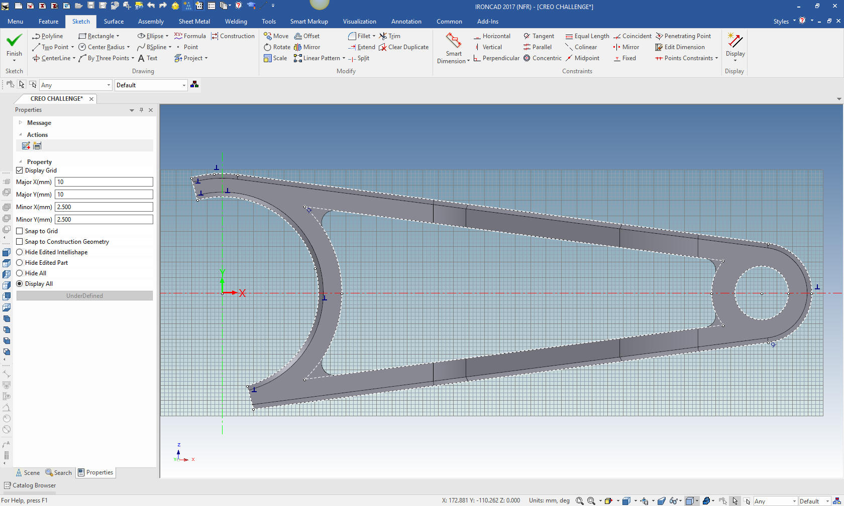 |
|
Note: IronCAD is such a innovative 3D CAD
system that I have to give a brief description of the basic 3D modeling
philosophy and a bit of history as compared to the major history only
CAD systems based on strict constrained sketching, what I fondly call
the Solidworks Clones. If you are already an IronCAD user or are aware
of these differences please continue to the training segment of the
article.
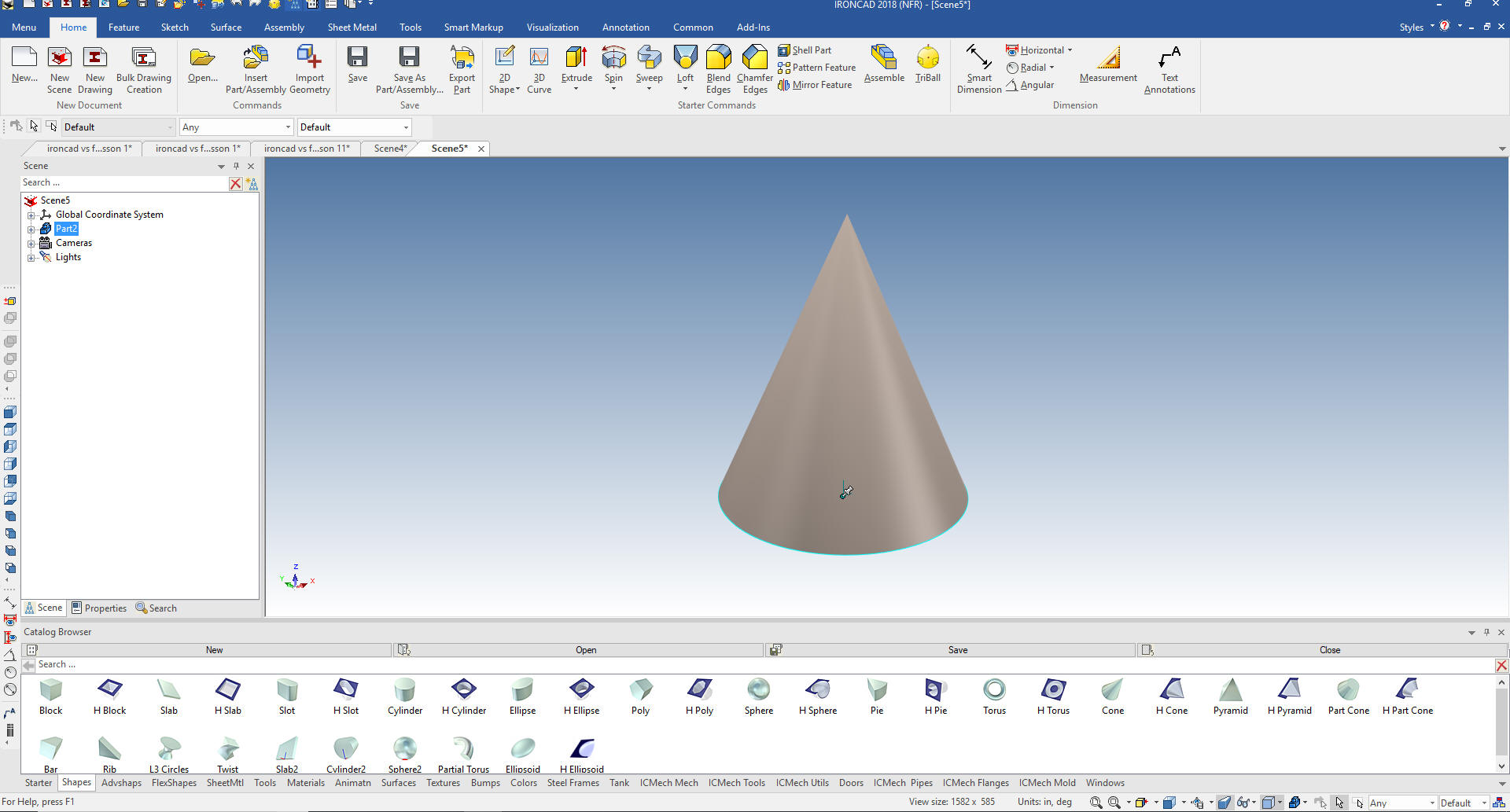
If you would like to join in: For more information or to download IronCAD This is a 30 day fully functional IronCAD evaluation including the Translators for all of the popular programs. Go ahead and import parts and/or assemblies. You can actually modify the parts faster than in the original system. Please start with the first lesson since they go in order of how you use IronCAD and introduces you the incredible highly productive flexibility. Learning IronCAD! Lesson 1 Setting up the Scene (Workspace) In this lesson you will not only learn IronCAD sketching but Streamlined Sketching or unconstrained sketching that can be applied to all other systems and along with feature based modeling can simplify the modeling process and increase productivity 5X. Streamlined Sketching in IronCAD Sketching has been a part of 3D modeling since the very beginning. I should know I was there. First with 3D wireframe design, then surfacing and finally solids. My first experience with sketching in solids was with CADKEY. No constraints, we continued to do it as we did it before. I continued on to IronCAD with non-constrained sketching. Even though all of the constraint commands were there. I really have never found a use for them. Now, I do understand their use in parametric design. But in the 20 years that I have had parametric design available I have done one project and it was only for a presentation to a customer that concluded it would be a huge waste of time. I really don't know how constrained sketching took hold. You don't need to use it in any of the programs. The only requirement is that you create a complete sketch for the creation of a solid. So lets get started Using Sketching along side Drag and Drop Design. IronCAD offers much more flexibility in design. First is Drag and Drop, Then Sketching and finally integrated Direct Editing. You cad select any of the processes as the the design requires. IronCAD has two sketching options. The Extrude, Spin, Sweep and Loft Wizards or edit any of the Intellishapes. Standalone sketches that can be used multiple times and also bring in .dxf or .dwg and edit them for complete sketches. The plane is not a feature in IronCAD. It is a component of the solid part. So you do not have planes as history items. This alone eliminates much of the clutter in the history. I use the Extrude Wizard constantly in my design process. It allows you to sketch standalone or on any face. You create the sketch and it will result in a solid, based on the sketch. Again we look to a drawing to convert to 3D.  So let's get started. We set the units to millimeters. 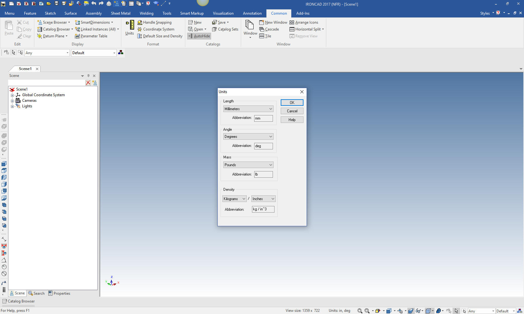 The first thing we will do is drag a block from a standard catalog. Notice that is has handles and the size box dimensions. There are a variety of standard catalogs and you can create custom catalogs. We set the block size. 100x60x50. The Size box dimension are turned on by a right mouse click in the scene and select show in the dialog box. 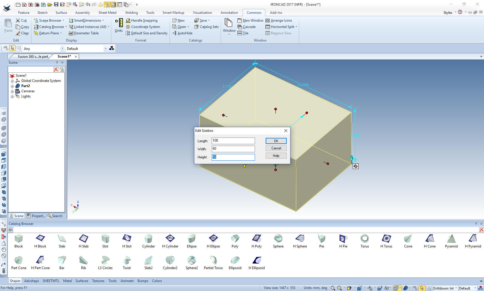 The catalog can be shown or automatically hidden. Hiding the catalog increases the work area. We now have the basic block ready to modify. 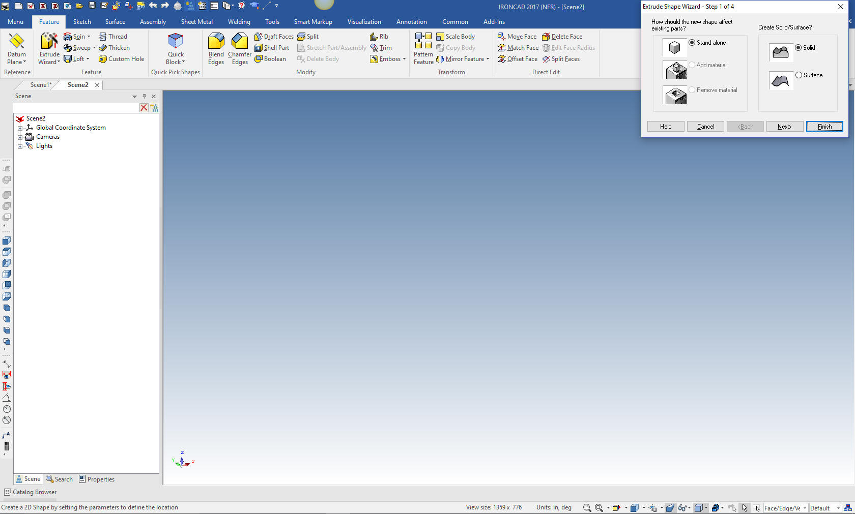 I will create the front cut with the Extrude Wizard by selecting the top face and we will remove material. 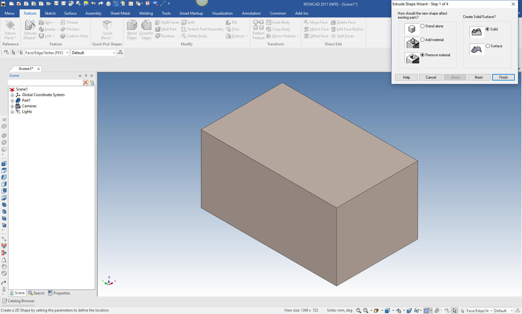 Projecting Edges This is a command in the Sketch menu. It is used to create graphics from existing features usually edges. Notice we do not constrain any features. Projecting edges is used though out this part. As you can see the Extrude Wizard creates a plane on the relevant face that we will be creating the extrusion. It is nothing more than projecting the two edges, defining the length of the pertinent edges and creating the diagonal line. Notice the projected entities already had editable dimensions, so there was no need to add a dimension to define it and there was no need to add any constraints. 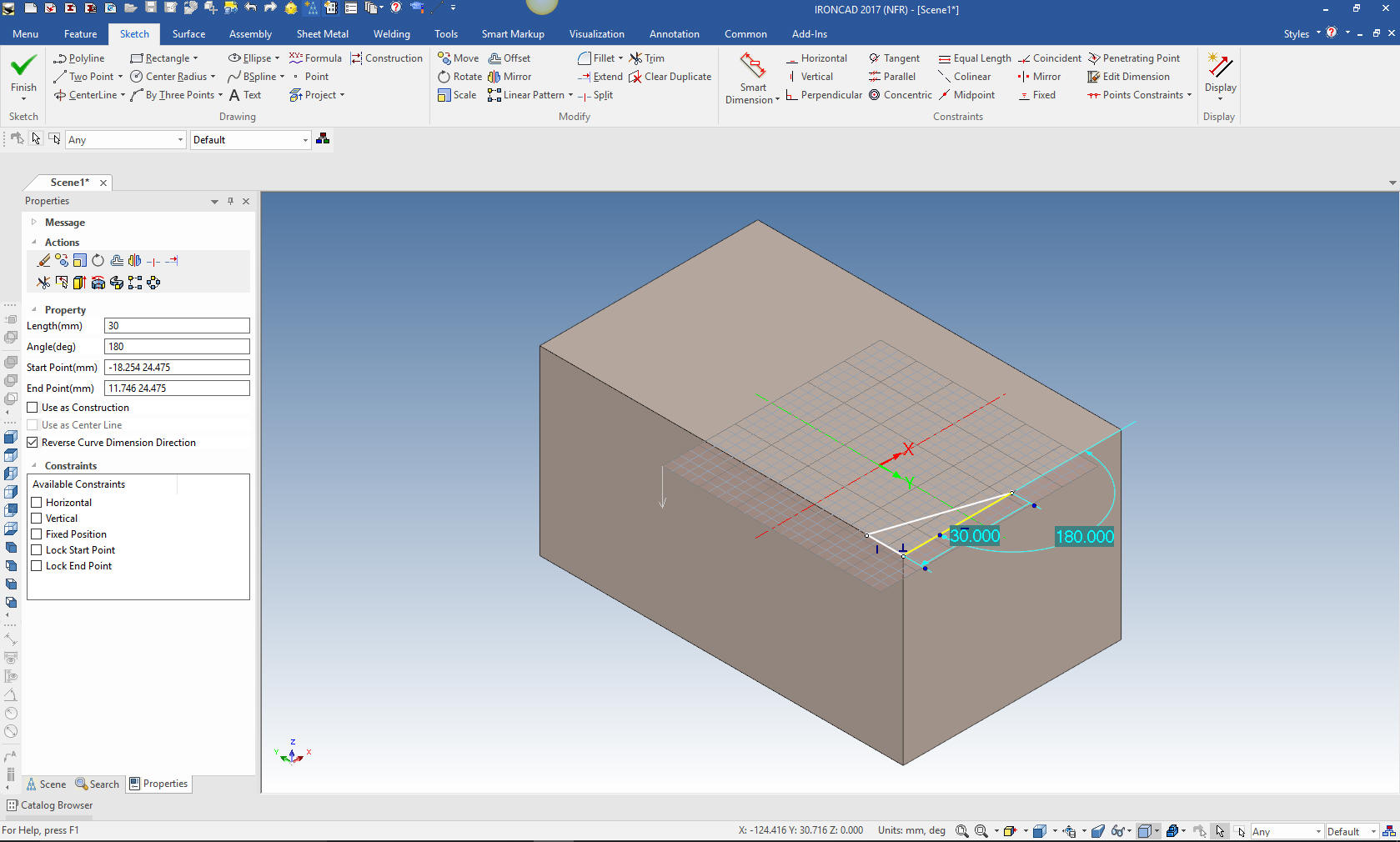 We select finish and pull the extrusion to the depth required. 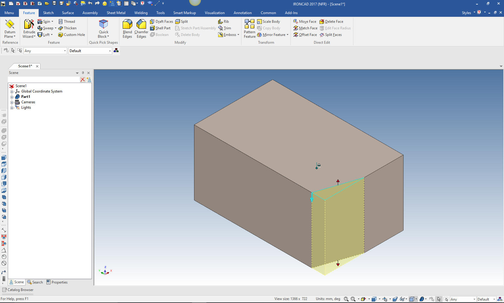 We will now mirror the feature with the Triball. With a push on the spacebar we can move the Triball only to any location. Of course, we move it to the point to which we need to mirror the feature. We select one of the small inner handles that set the mirroring direction. We can move, copy or link the feature. Linking will automatically show any changes to either of the extruded cuts. I could create all of the features and mirror them but I want you to see the Triball in action. 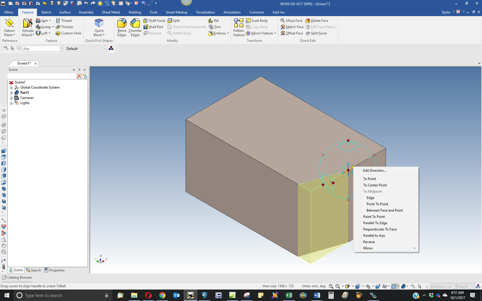 We will now make the other front cut by again using the Extrude Wizard. We project the edges add the diagonal line and edit, trim or extend the two other lines depending on how we project the lines. 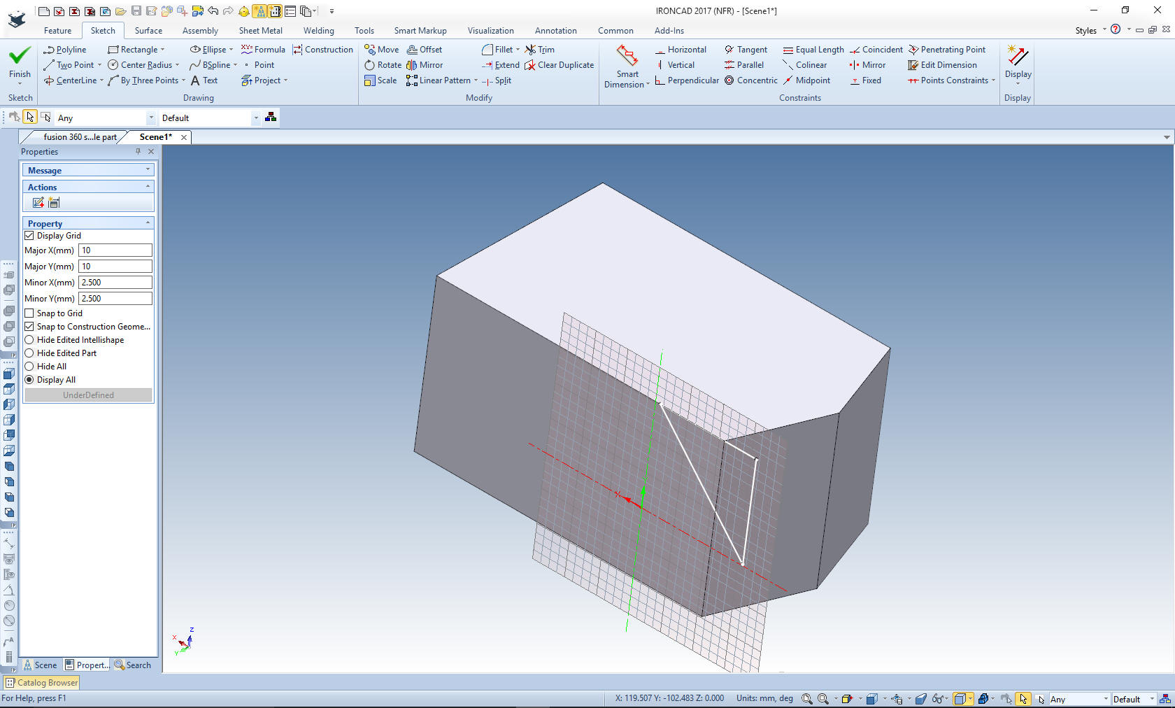 Finish the command. 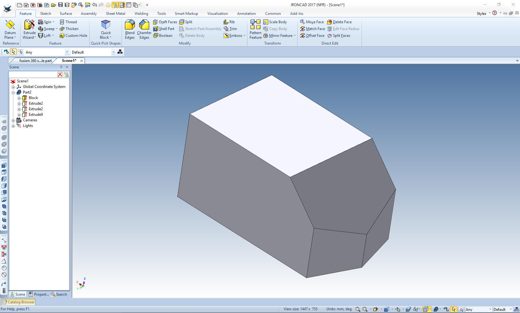 Again using the Extrude Wizard I create another plane, Using the Triball, I put it in the center of the inclined face and then lock the axis that I want to rotate the plane, then using the inside handles I point to the lower left corner of the part setting the plane in the correct orientation. 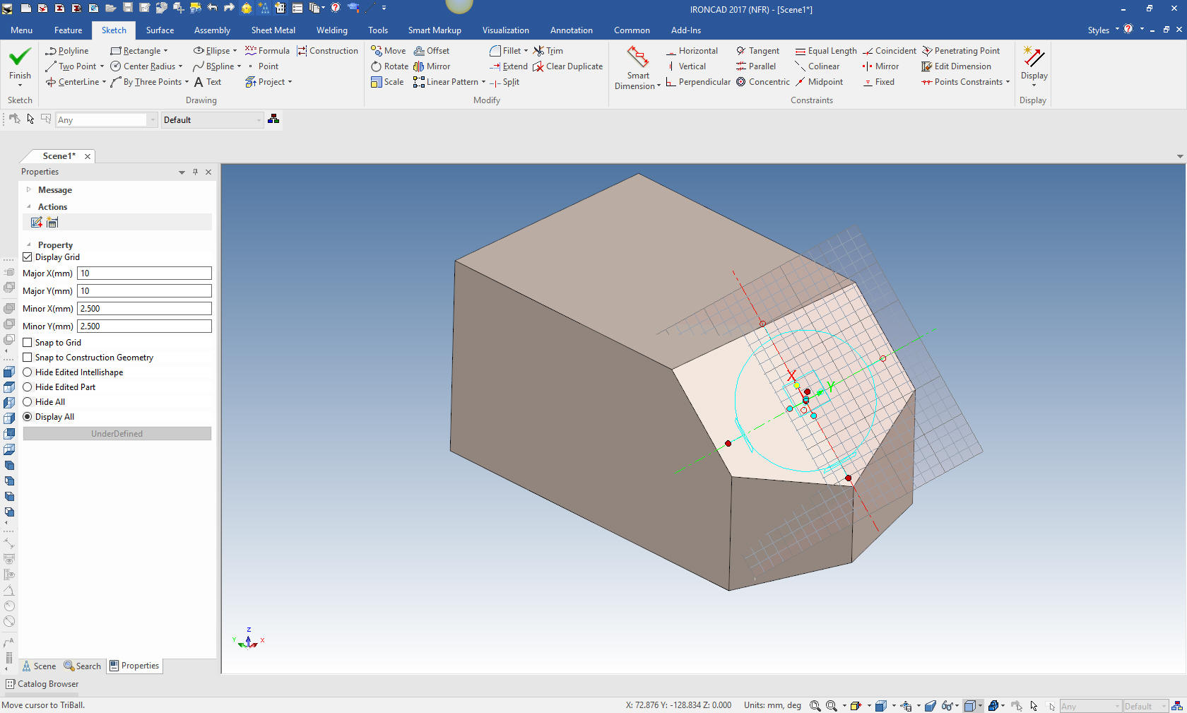 I turn off the Triball with the escape key and proceed to create a rectangle. The size is not important as long as it includes the faces we need to cut.  Let me show an alternative method on creating this feature by using a Hole Block. I drag a Hole block on the diagonal face. I have sized it by putting it on top of the face and aligned the points to the center by pulling the handle and snapping to existing features. Then locating the Triball to the center to rotate the Hole Block. 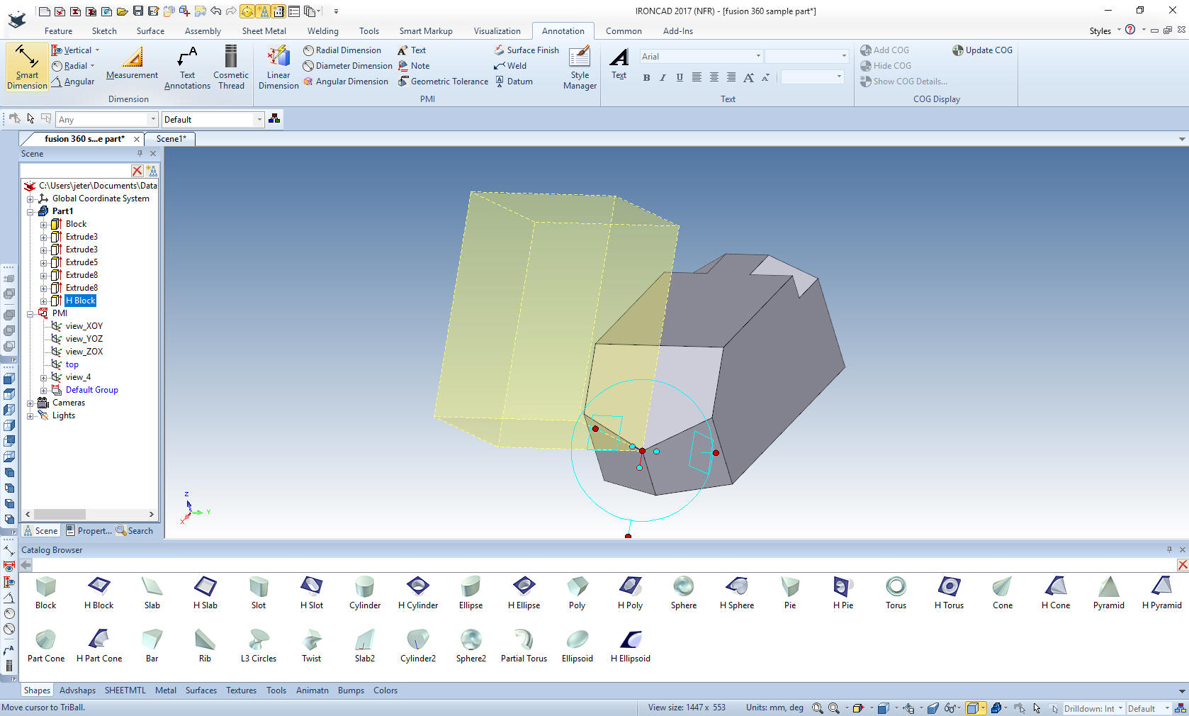 Again with the Triball I lock in the axis of rotation and select the inside handles to point to the lower left corner in this case. You can see I have the same results. Just pull on the handle of the Hole Block to extend the block to include all of the faces that need to be cut. 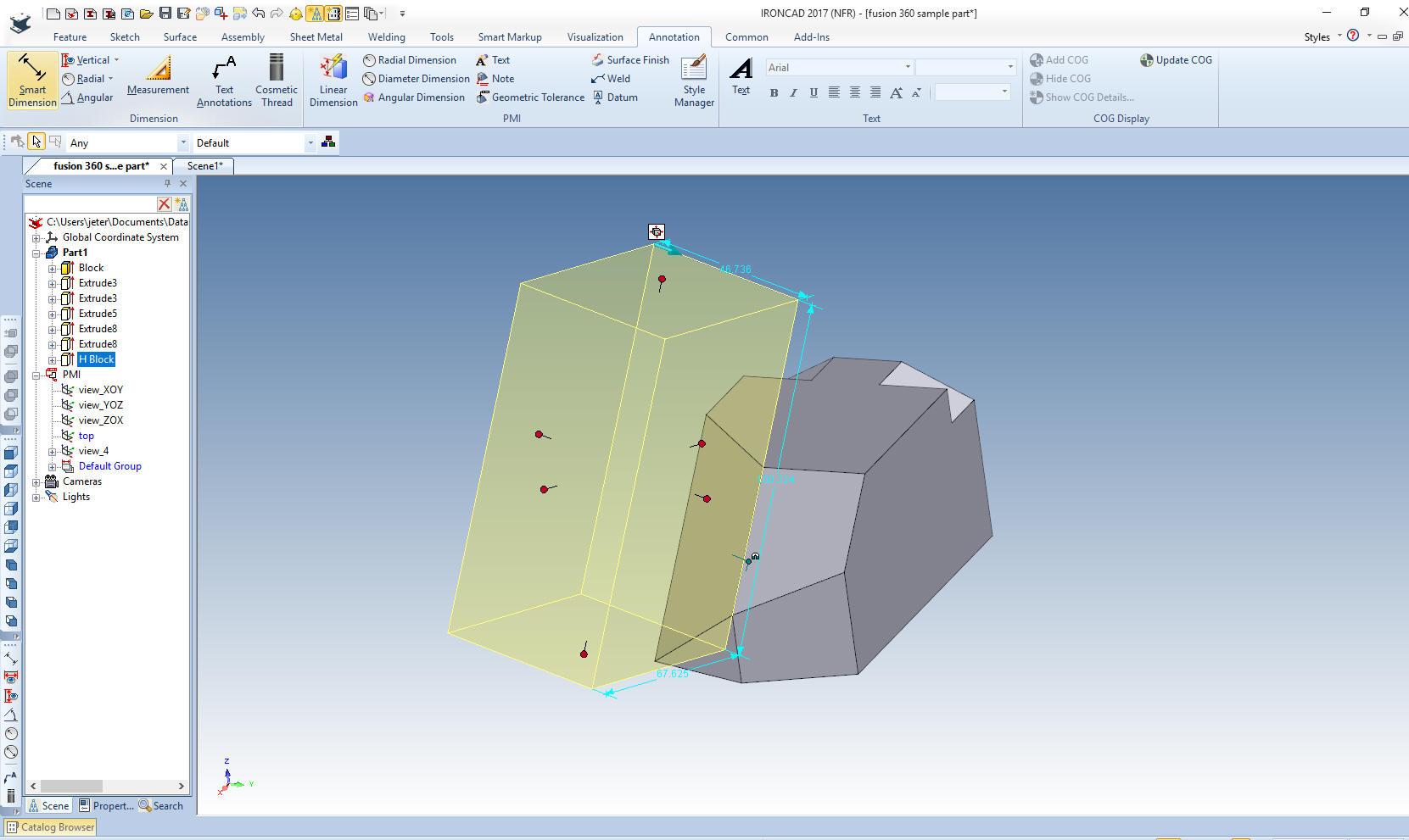 We finish the command and we have our cut.  We have to mirror the new feature. I select the feature and turn on the triball. I reorient the tribal by hitting the spacebar and and selecting global. I then select the inside handle that allows me to correctly mirror link the feature.  The feature is mirrored. 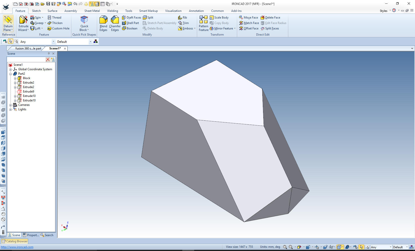 Again using the Extrude Wizard we now do the back cuts using the same as the front cuts. Just projecting the two edges, editing the lengths and adding the diagonal line. 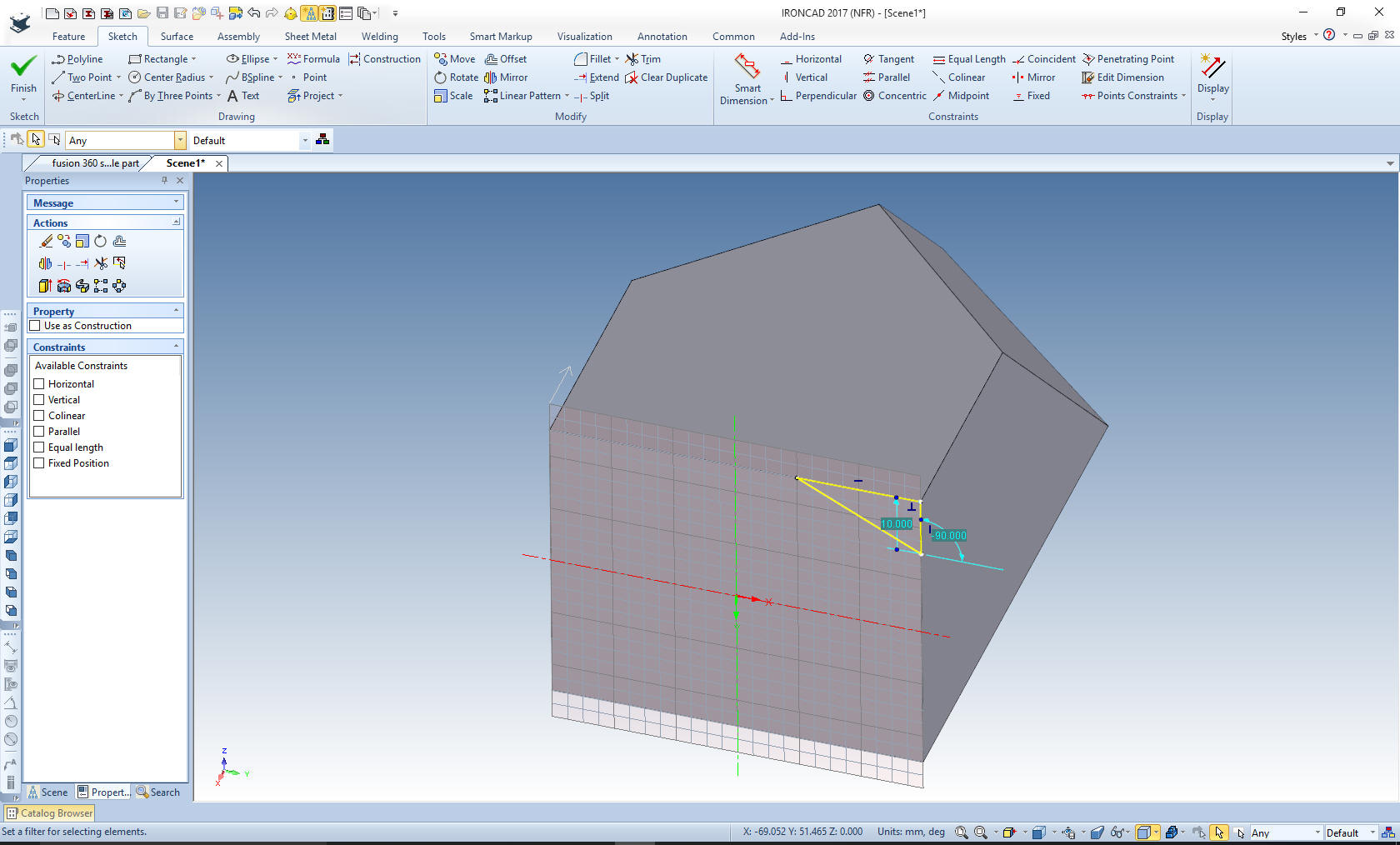 Finish the command and setting the depth and again use the triball to mirror the feature. 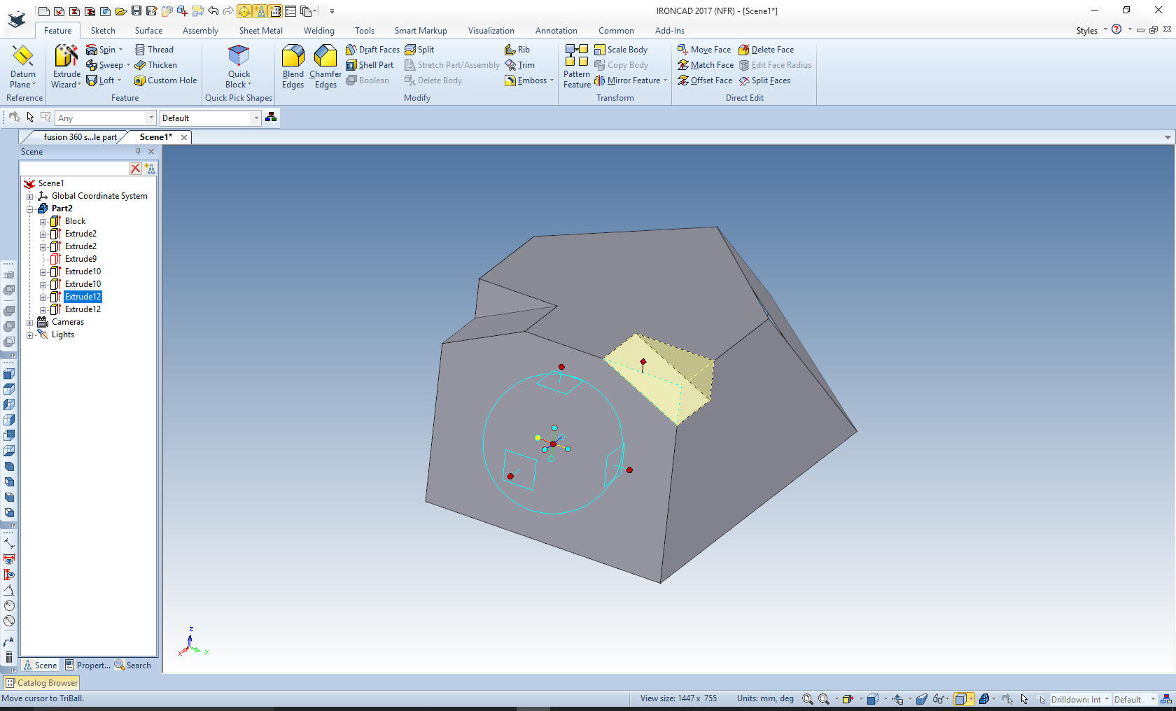 The part is done. How long? No more than 5 minutes. Never going to a sketching format. Just creating the planes in 3D space. Projecting the edges and edit the length of the lines. With effective use of the incredible Triball. 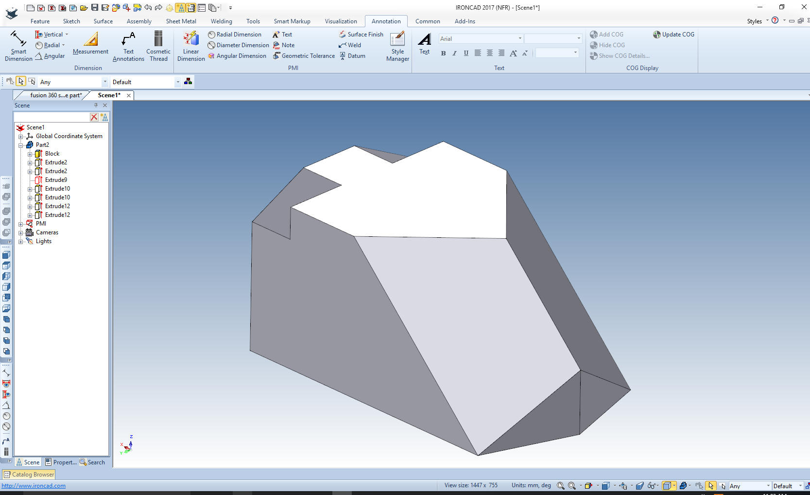 You can see modeling in IronCAD uses a mixture of drag and drop, feature based modeling and streamlined sketching. A far different way than many of you are used to. Streamlined Sketching Only Yes, yes you can sketch only. Sometimes it is easier just to sketch a part. Here is the drawing.  An Exercise in Sketching! My default is inches, so we set the units to mm. Let's get started. 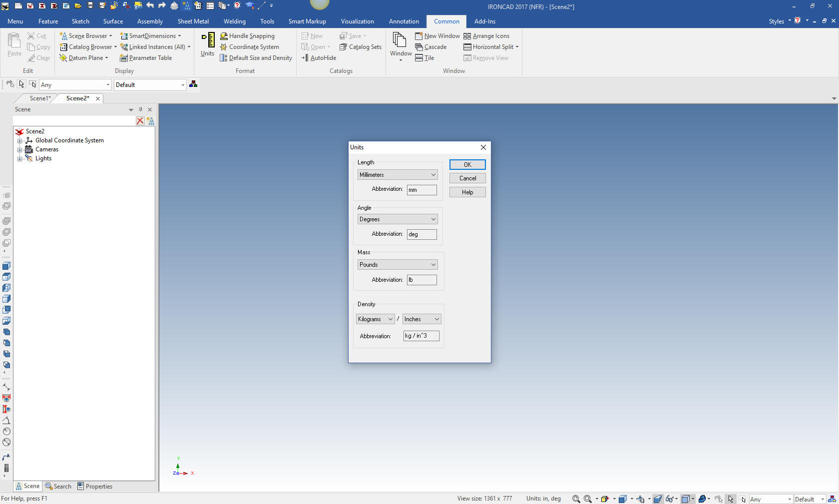 We insert a sketch with the extrude wizard. We will create a stand alone part. 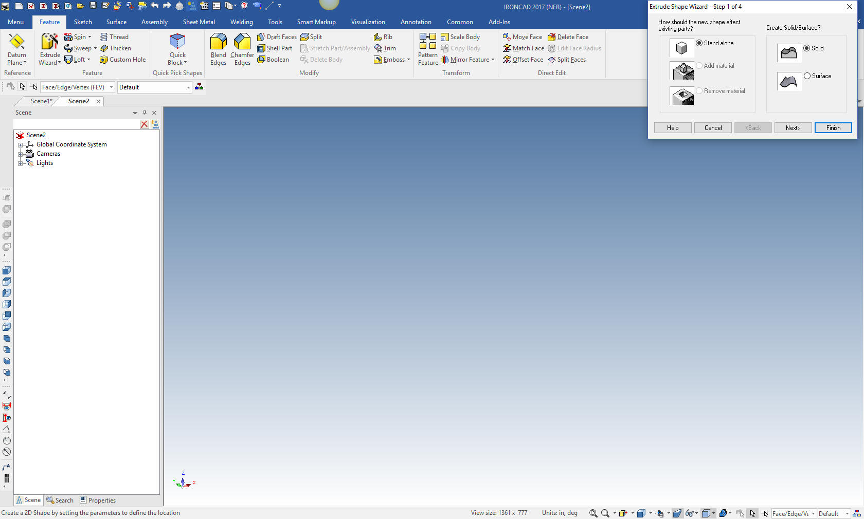 We select finish and the sketching plane comes in ready to go to work. This is an automatic extrusion and we will set the thickness later 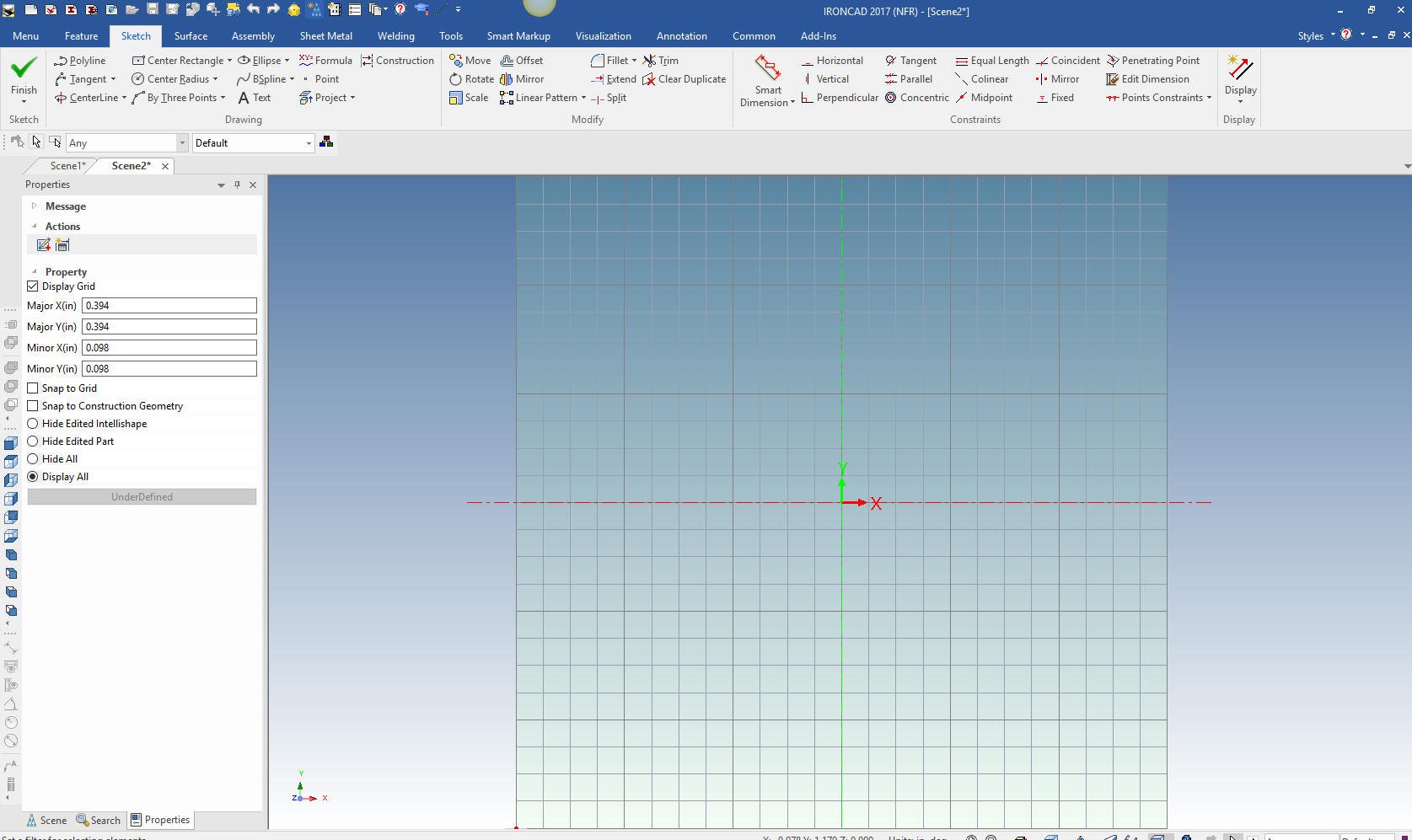 I first create a rectangle with the rectangle with corners command. I use the right mouse button that allows me to input the size of the rectangle 65 x 24. Note: I have to make a confession. I never knew about the right button edit function until I started doing these exercises. It shows you how little I used the sketching function. I have been using this program for almost 20 years with tens of thousands of design hours. I have never sketched a part! I usually project edges to modify the solids. 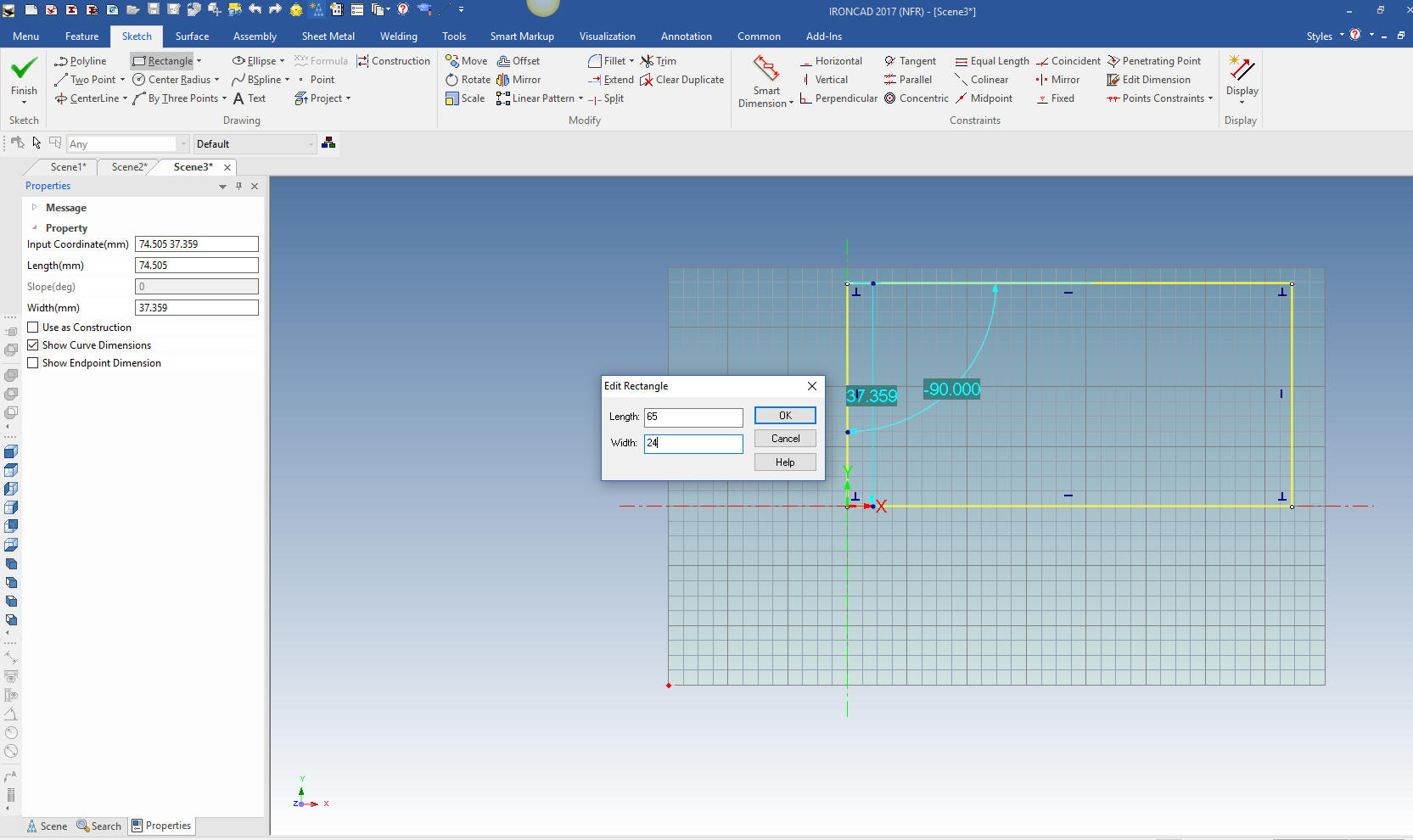 We will now create the vertical and horizontal offsets that are the basics for our part. We will focus on the bottom profile here. This is the basis of Streamlined Sketching or non-constrained sketching. I assume PTC was only focused on parametric functionality with it emphasis on constrained sketching. It rarely needed in single part design and adds a huge amount to time. 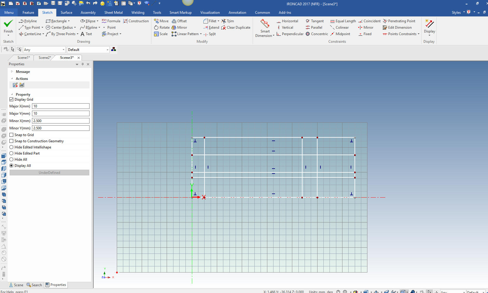 We will add the 10 mm circle by center and location. No need to input a dimension the graphics drive the dimensions. 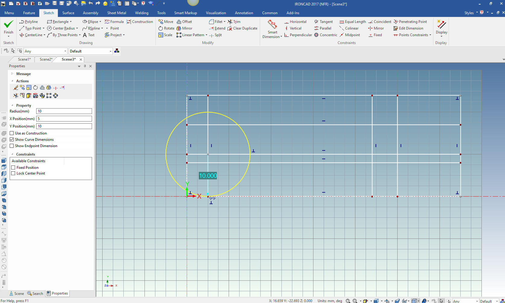 We will do some trimming or deleting construction geometry to make it more clear for the creation of the angled line. We create a two point line with the right mouse button and set the angle leaving the length arbitrary.  We clean up a bit more and put in a two tangent and point circle using the right mouse button which brings up a dialog box we enter 14. 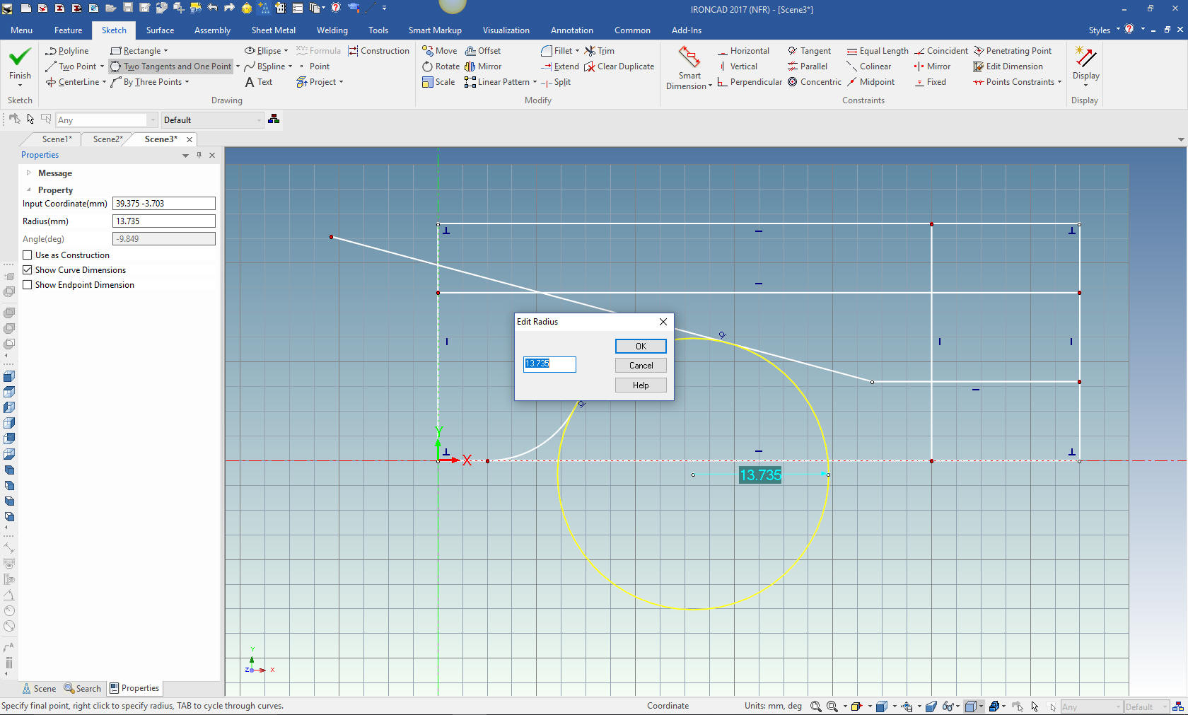 We trim the entities and are ready for the top profile. 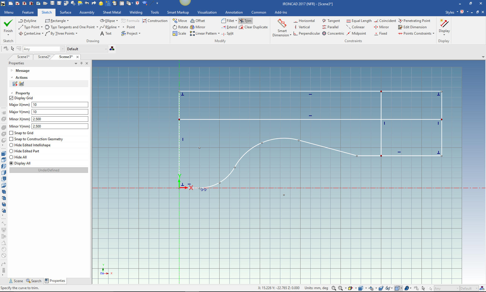 We have to create another offset line from the affected horizontal line at 15 and extend the applicable line to establish the center point for the Radius. Again we let the graphics drive the dimension. I will not concern myself with the R 10 since it is basically double dimensioning. 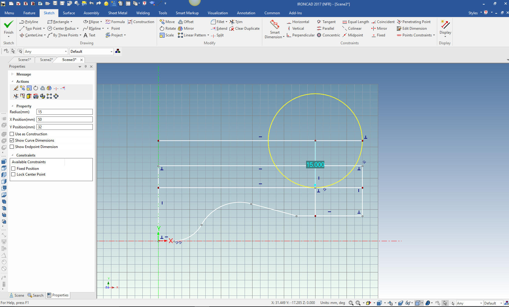 We just trim the entities and we are done with our sketch. What are you talking about, Joe, there are blends and chamfers?? Why waste your time sketching a blend or chamfer. This is what I have called "Feature Based Modeling" as compared to "Sketch Based Modeling" (if you can even consider sketching, modeling). I showed this to a "Constrained Sketching Only" designer and he instantly went in and edited a radius and said "Look it blew the sketch" I had to take him by the hand and show him how to do Streamlined Sketching. This is how you do it on the drawing board. Yes you may have to delete an entity and recreate it. Much less complicated than a constrained sketch.  We select finish and the sketching of our part is done. We set the thickness to 10mm 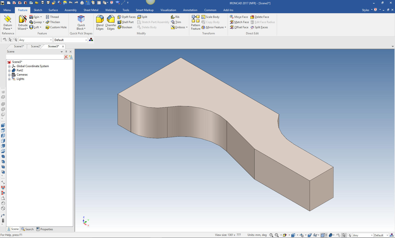 We just add the blend and two chamfers. 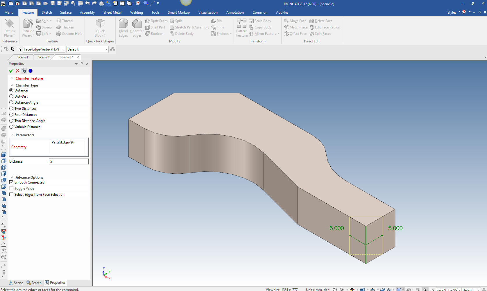 We are done with our part. 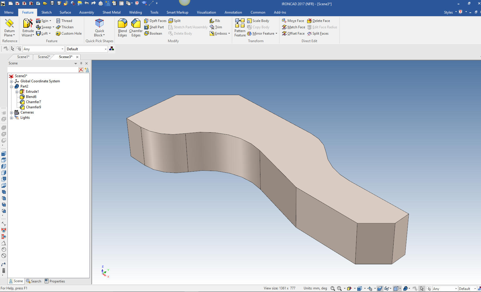 Here is an interesting study in sketching only. I saw a modeling contest sponsored by PTC. High Speed Sketching in Creo? What? It took me awhile to discover this was not 3D modeling it was an exercise in sketching! HOW FAST CAN YOU CREATE TWO SKETCHES?? Not being the best sketcher I had to do it a couple of times and had it down to 10 minutes. I said "Good gawd who cares!!". Now Creo (Pro/e) has probably the very best sketching process, since it developed this overly complex, time consuming constrained sketching in 1988. Can you believe it is 2018, 31 years later and we are still using this convoluted dated paradigm? What's worse it has become the de facto standard with all of the other popular 3D CAD packages being nothing but Creo clones. We have the complete industry now based on this idiotic paradigm. Here are the two sketches in IronCAD. It shows no constraints. Yet completely defines the part. In Feature Based Modeling any blends or fillets are not done in a sketch. They are done later making any changes much more accessible. I find depending on the sketch a bit more confusing than working with features. 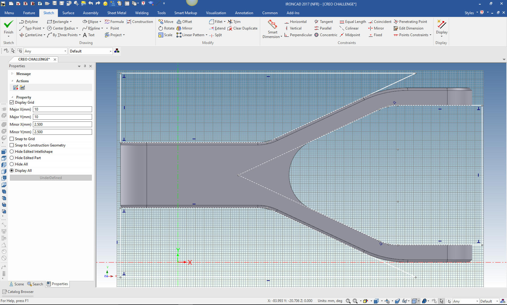 The final part.  Standalone Sketching or the Independent Sketch The independent sketch is available in the sketch menu called the 2D Shape. It gives you the ability to do sketching and you can save it in any level of completion. The Extrude or other Wizards require a completely defined sketch that ends with the solid. I will just give a small example. You can copy these sketches and entities so you can utilize the different sets of graphics later. You can use the graphics of a .dxg or .dwg and easily create the model. I create a new file. I go to the sketch menu and create a 2D shape. This brings up a grid ready to start sketching. The sketching can be used identically as the extrude wizard except of course it can be saved in any level of completion and requires an added process to create an extrusion, spin or sweep also you can extract a curve. 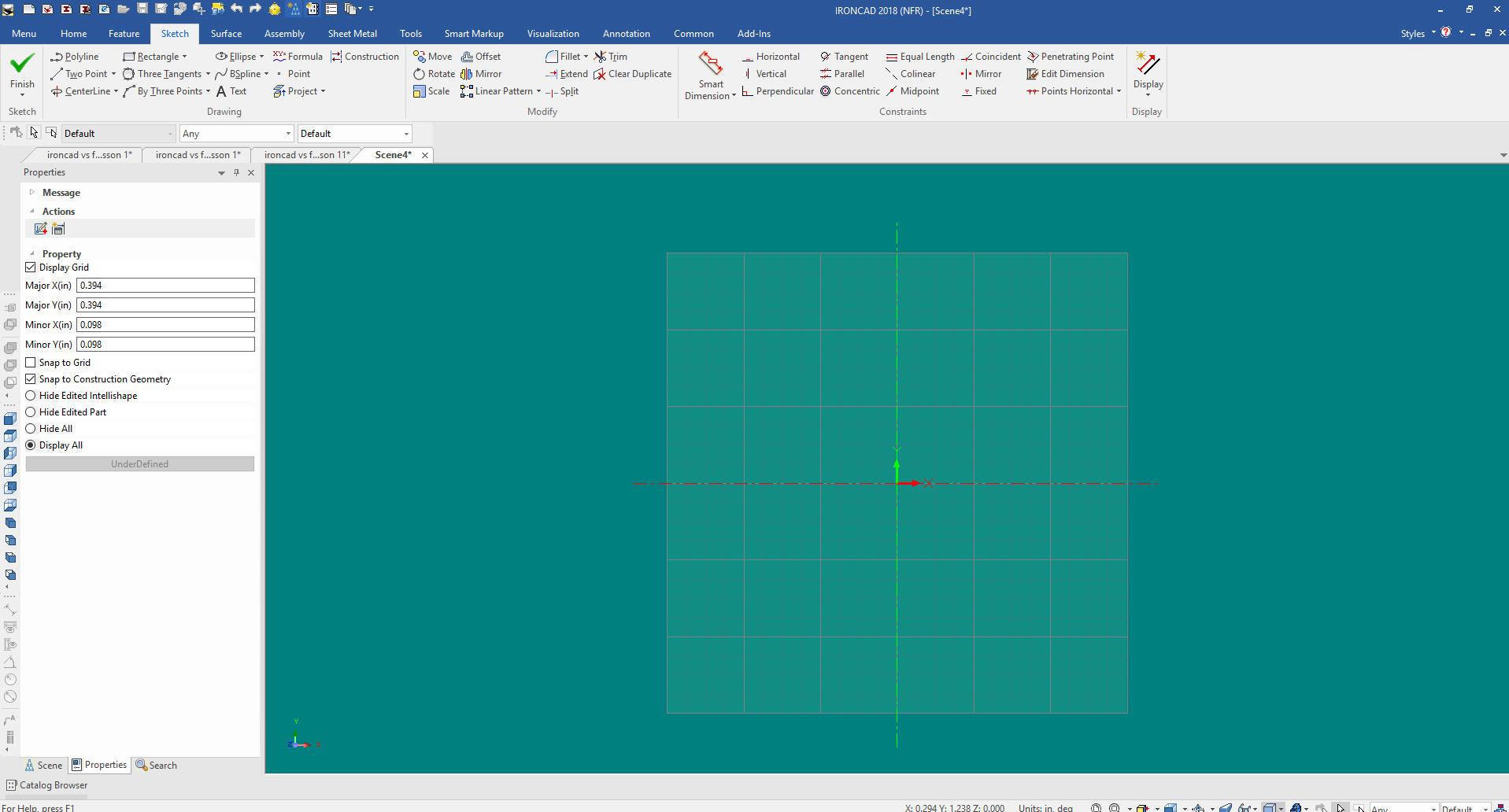 I have created a .dxf from the first lesson AID (drawing). I right click in the grid and import the .dxf 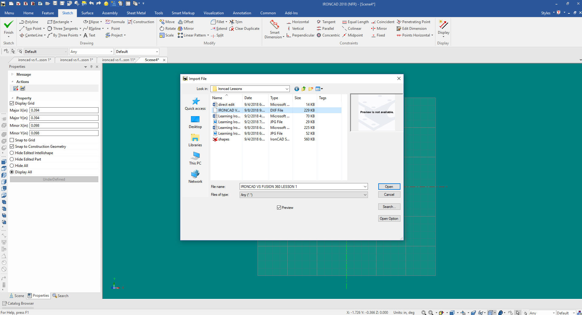 I have change the back ground to highlight the graphics that are in white. 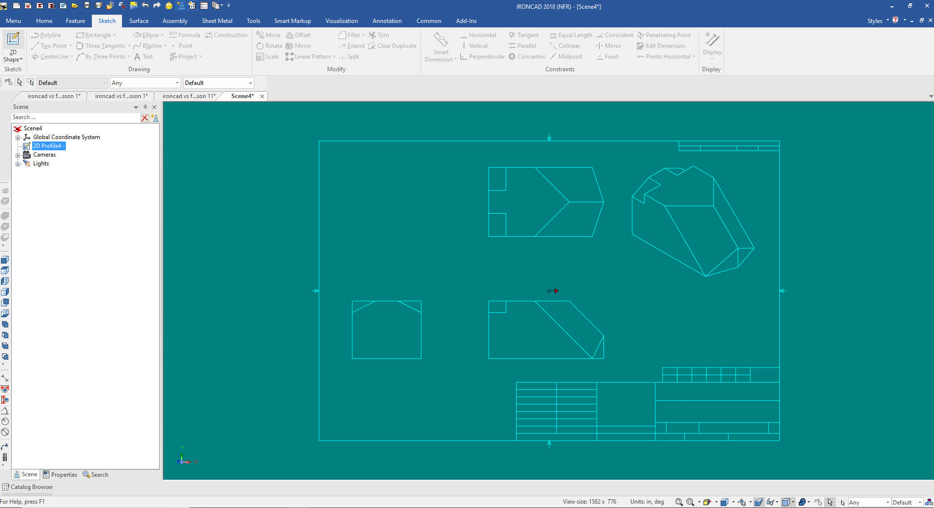 You can copy and edit the different sketches if you have different parts on the dxf. This what it looks like when you edit the sketch. 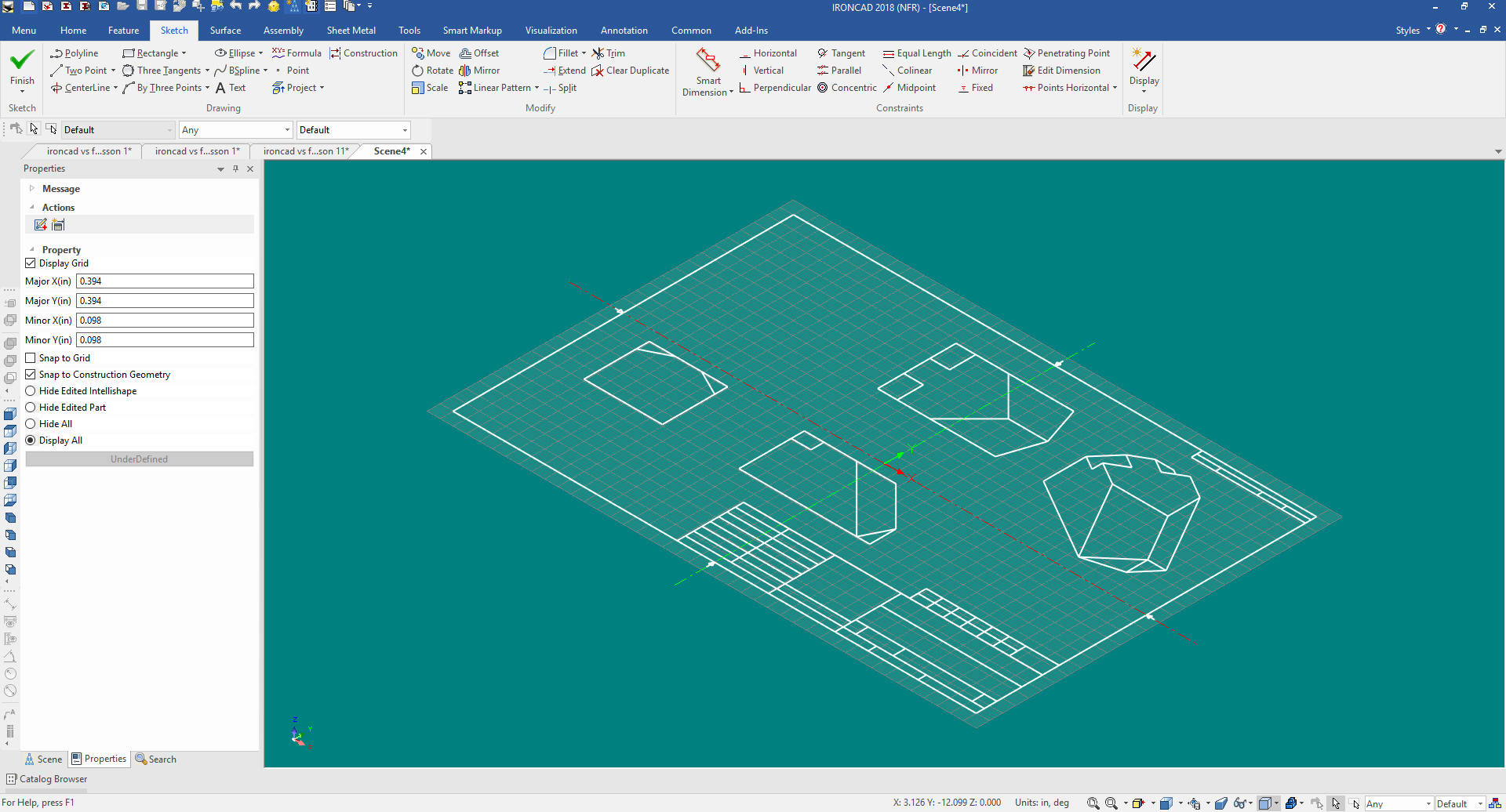 I haven't created a model from a .dxf for years. But this is to show you how a standalone sketch can be used. Many times I will use the standalone to transfer graphics to create a similar feature in another part. Here is a video showing how to create a model from a .dxf Utilizing the Imbedded Sketch in the IntellishapeA sketching lesson in IronCAD would not be completed without an introduction of working with intellishapes. The intellishapes are the standard shapes in the Catalog. All of the shapes are made up of editable sketches and other features. I want to show you how to edit an intellishape.I will create a new file expand the catalog and drag and drop a cone into the scene.
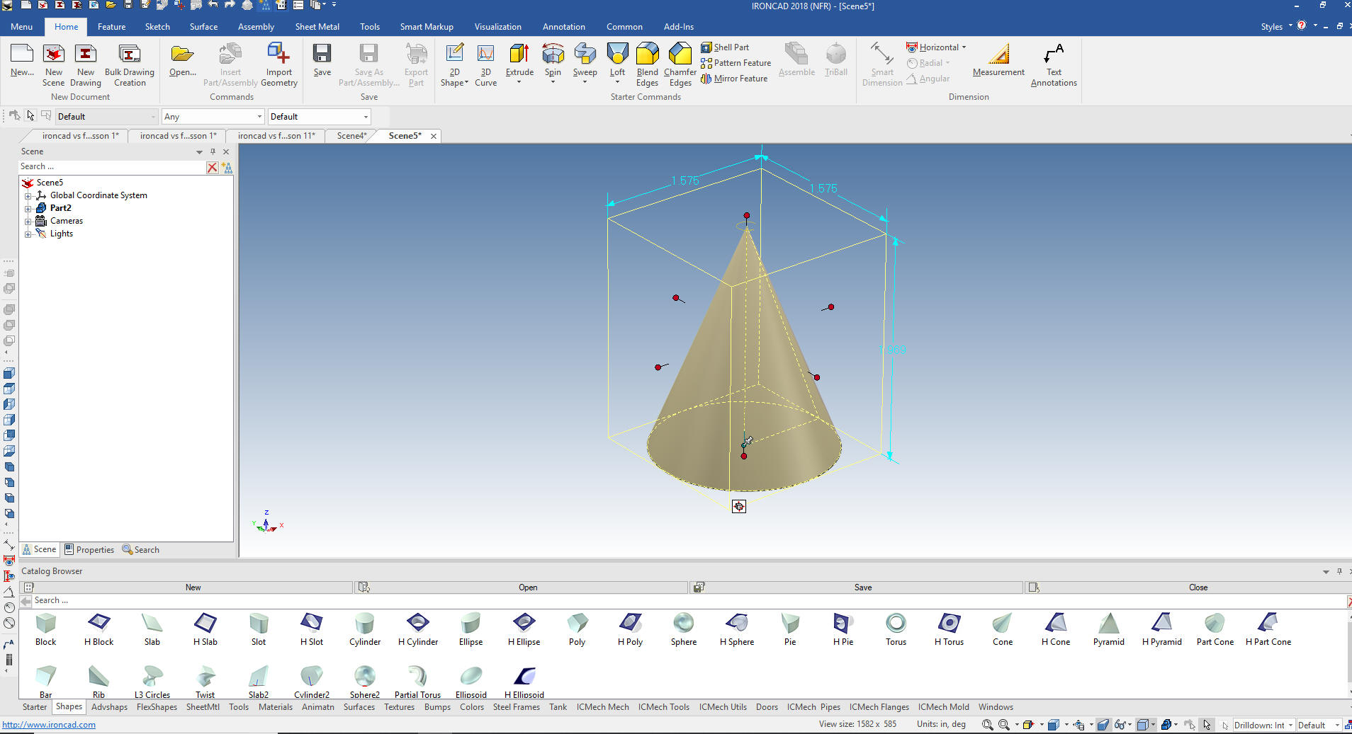 We then right click on the feature and select Edit Cross Section. I use the cone or hole cone in the place of the spin wizard. You can move it into place much easier. 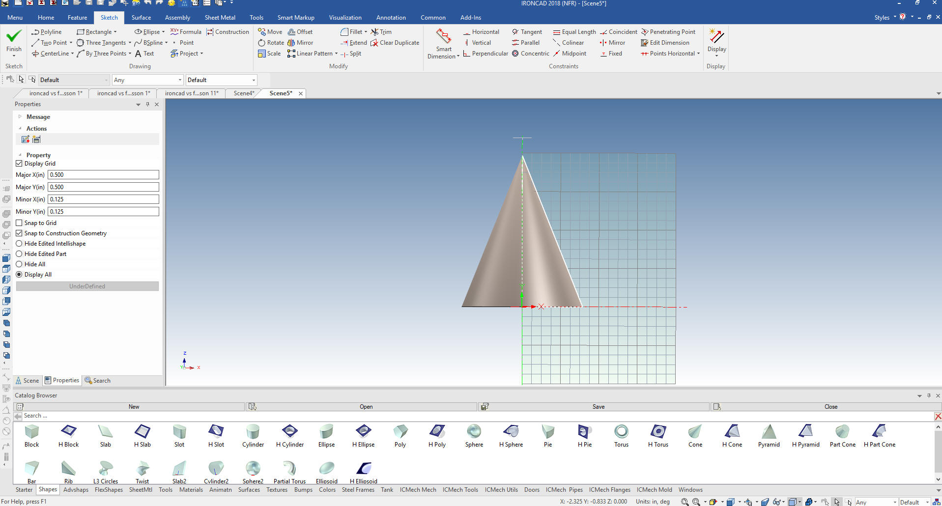 Now we can edit the sketch. I will delete the existing graphics and create a new sketch to show you the flexibility of this command. Again we do not constrain the entities. 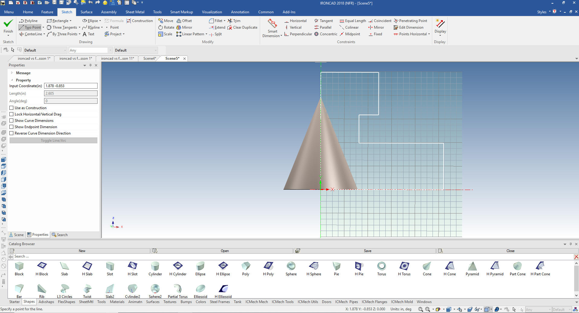 We select finish and we can see the new model. 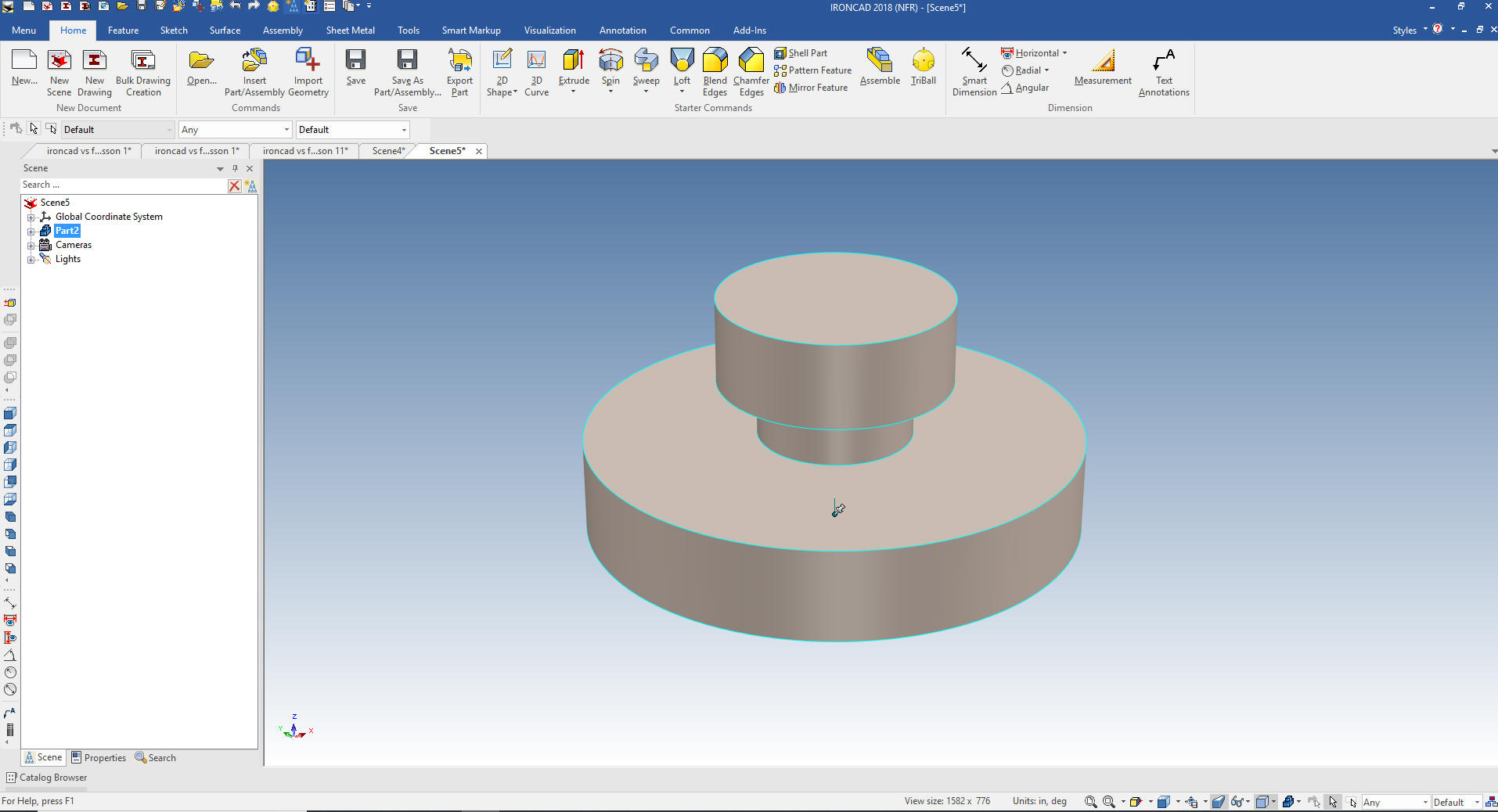 We can add a few blend since we would never sketch them, only in special cases. 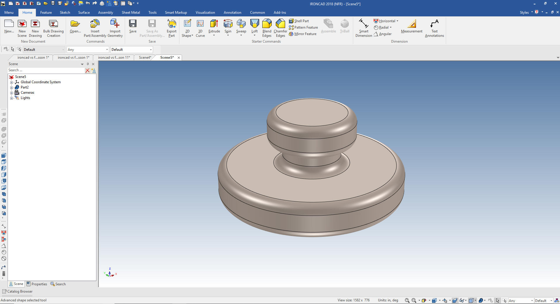 One more thing I want to show is the torus. I drag and drop a torus into the scene and left click it until at the feature level (Yellow). 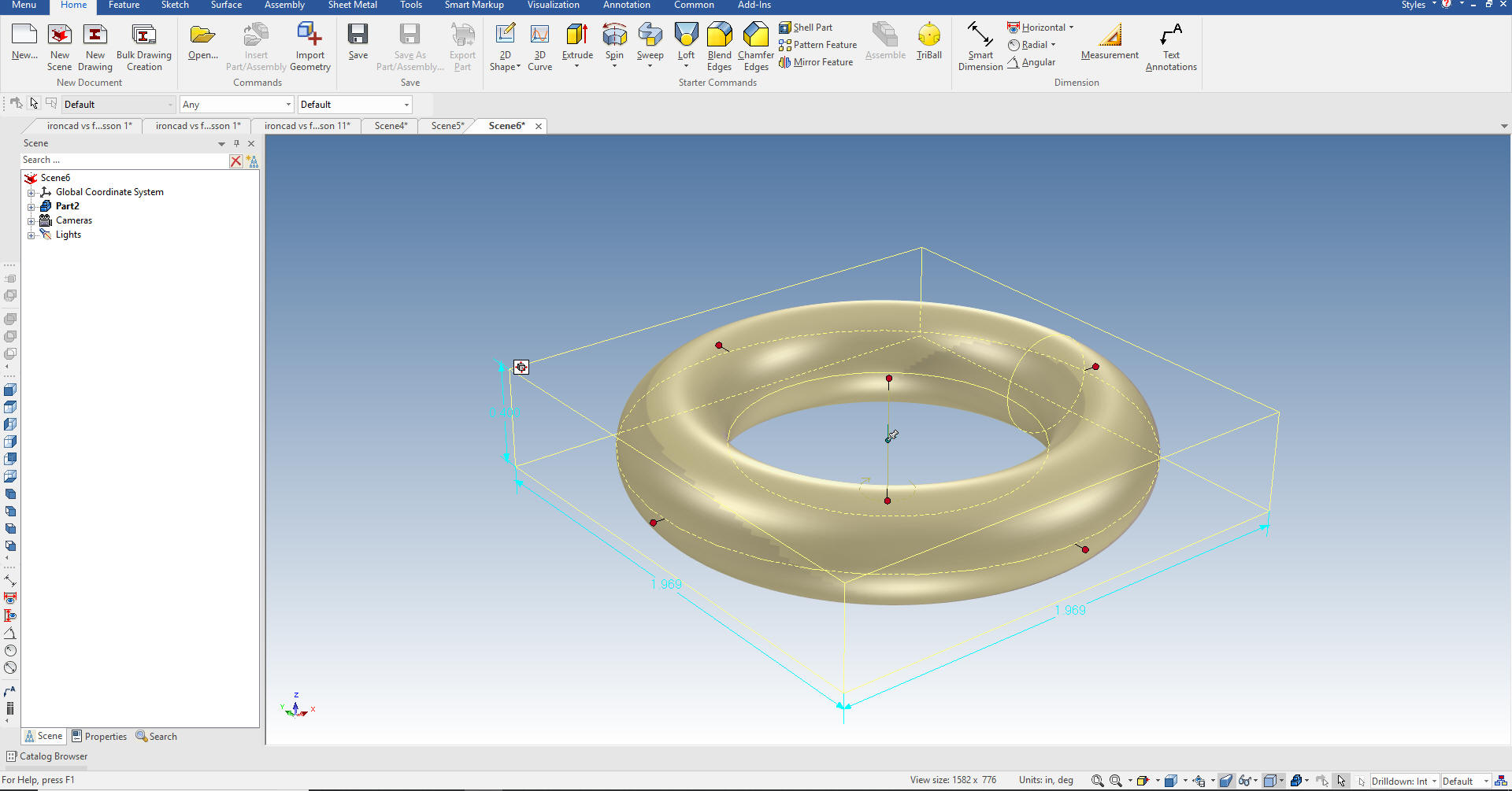 I can now edit the sketch. 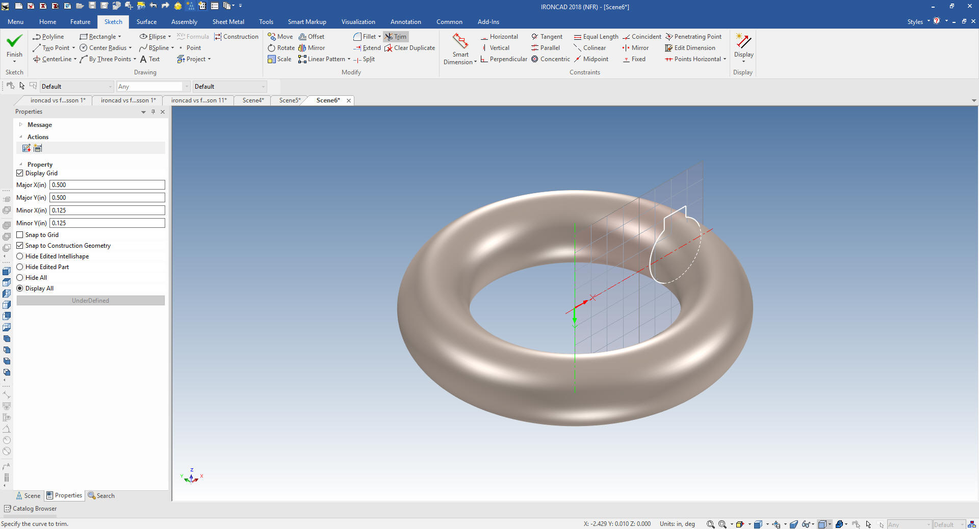 I select finish and the change is done. 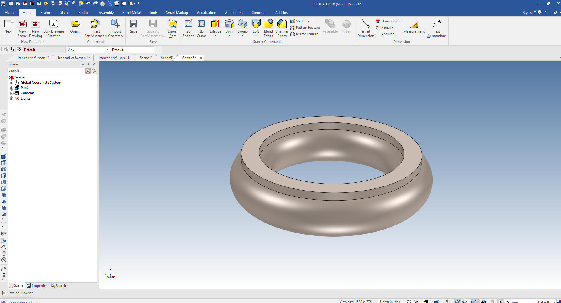 We have other editing options. 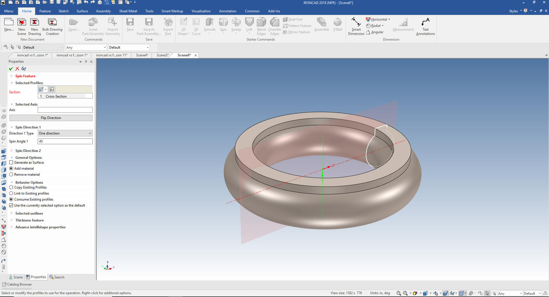 We select 90 degrees and select finish. I added another circle in the center. This is just to show the flexibility of many of the Intellishapes. This is great for making pipe elbows. Remember in IronCAD you only make it once. If it is a feature, part or assembly you use often you can create a custom catalog and have them instantly available for new design. 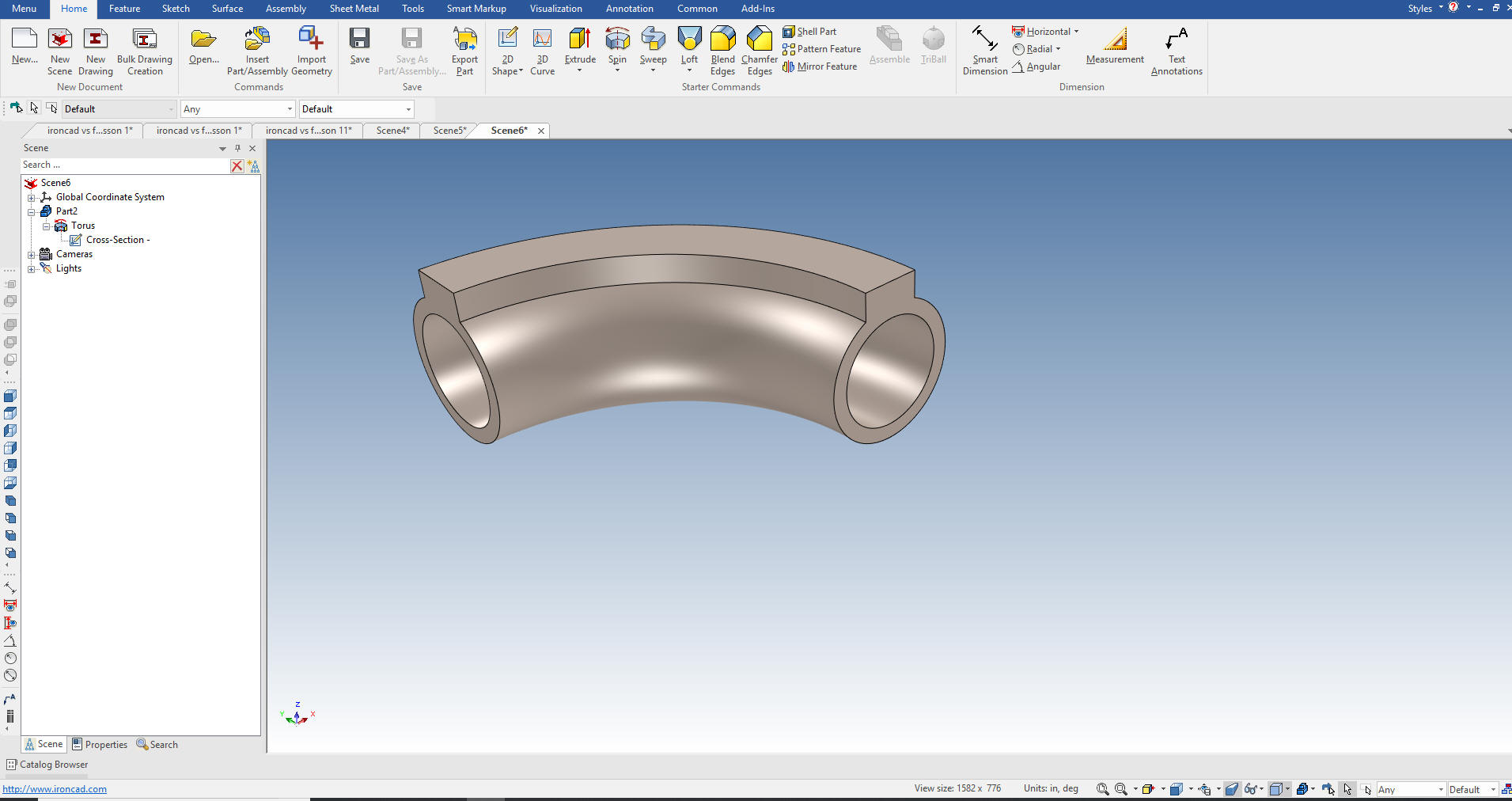 I think that is about it on sketching in IronCAD. Lesson 4: The IronCAD Intellishape Deconstructed In 1988 the world was introduced to the first solid modeling system designed from the ground up. This, of course, was Pro/e. It was a mile stone in 3D CAD. It was also the most convoluted solid modeling systems. I believe they bit off more than they could chew by adding parametrics in the design process. It would have been nice to have a simple modeling program. But parametrics is an integrated part of Pro/e and added a high level of complexity to the program. By far the worst feature of this product was the separate part, assembly and AID (Associated Information Document (drawing)). This has caused a nightmare in PDM and the attempts to manage engineering documentation with PLM. Sadly, this feature has become the de facto standard accepted blindly by the PLM gurus supported by the major CAD systems. There is huge money involved in this failed experiment. IronCAD showed up in 1998 with the single model design environment. It was not the first program to use this highly productive feature, I was already using CADKEY which also used the single model design environment. So my introduction to Solidworks, nothing but a PC based Clone of Pro/e, was hardly enlightening. I was already doing complete projects in one file. Why in the world would I move to a system with such a complex design environment? The second feature that made Pro/e a horror show was the constrained sketching. This is another feature I thought was overly complex when being introduced to Solidworks. The training was all in constraining the sketch. I chuckled and said this was just too much work. Now just because I found it cumbersome, don't think I have not used it. I took on Pro/e when it moved to the PC. The few jobs I did, converting Boeing structure drawings to models were tortuous as compared to CADKEY and IronCAD. I really don't remember doing a lot of constraining. But then this was 18 years ago. Then I took on Solid Edge, Solidworks, Alibre and finally Inventor. I spent a bit of time in each and decided it was not worth it. I used the CAD systems I sell and support in my design services. I saw a some Fusion 360 training videos on line and decided to do some comparison exercises. I quickly found that the presenter was using constrained sketching and it was hugely time consuming and overly complex and these exercises turned into a "Study in Modeling Techniques". Where I developed "Feature Based Modeling and Streamline Sketching. But it wasn't just Fusion 360, I found Solidworks users also were in the same situation of constrained sketching. Here are some actual exercises. Please review a few and you may see how much time you or your designers are wasting. Even a few of you designers can see the wasted time by constraining every sketch. You don't have too, even in your Pro/e (Creo) clones. You can actually use these articles as training tools. IronCAD vs Fusion 360 IronCAD vs Solidworks Again please download IronCAD and start experiencing the increased productivity. Today, engineering is a bottle neck due to the time consuming design paradigm of the major 3D CAD system. IronCAD can increase productivity on conceptual design 5X and with modifications 10X. This translates to real cost savings. Is 3D CAD Productivity an Oxymoron? For more information or to download IronCAD Here are some exercises that you can do. They will introduce you to more Streamlined Sketching and Feature Based Modeling. IronCAD vs Fusion 360 IronCAD vs Solidworks Again If you have questions please skype me. I am usually available from 4 am to 2 pm weekdays. Weekends usually from 4 am to 10 am. Maybe later, if I have some work, you can always give it a try. Again please send me an email so I know who you are: joe@tecnetinc.com |
|
Please feel free to stop by our website below for a variety of articles on the State of our Industry, interesting articles on 3D CAD Productivity and a few of our projects!
Viewpoints on Today's 3D CAD and
Engineering Industry
TECH-NET Engineering Services! We sell and support IronCAD and ZW3D Products and
If you are interested in adding professional hybrid modeling capabilities or looking for a new solution to increase your productivity, take some time to download a fully functional 30 day evaluation and play with these packages. Feel free to give me a call if you have any questions or would like an on-line presentation. For more information or to download IronCAD or ZW3D Joe Brouwer |

TECH-NET ASSOCIATES | RENDERING OF THE MONTH | CAD•CAM SERVICES
HARDWARE | TECH TIPS | EMPLOYMENT | CONTACT