|
IronCAD is unique and the most productive
conceptual 3D CAD system. Change is incredibly easy. You can have
several iteration of your design in the same file.
- Single Model Environment - Parts and
assemblies in a single file
- Drag and Drop Design from Custom or
Standard Catalogs
- The Only Integrated History/Direct
Edit Design - Both used in your design process
- Copy and Paste Directly from Different
Files
- The Incredible Feature, Part and
Assembly Manipulator - The Triball
We have the native IronCAD and STEP File Available here for download
Note: IronCAD Model .ics/AID .icd native
files must be copied to the same folder.
3D Modeling is the basis for our
engineering. That is the only place where productivity is paramount.
You can have all the PLM/MBE gurus debating data management, but it
does not add one smidgeon of productivity to the design process.
Top down or In-Context modeling is the most productive
feature of 3D CAD. Most systems tout this but each part is still an
external part. We are talking about a single model or multi-object
design environment. Both of the systems we represent offer this as
the "normal" design process. Thereby increasing your productivity 20
to 30%.
In these exercises I not only focus on modeling techniques, but
also on much more productive systems to do our designs. I hope you
enjoy them and learn something. If you are in management, understand
that all 3D CAD systems are not the same. Cutting your engineering
costs is very simple. Even your legacy data is not a problem. Please
feel free to give me a call. There are millions of man hours wasted
every day with poor modeling techniques and dated 3D CAD
systems that cost a fortune. Productive 3D CAD systems do not have
to be expensive.
Joe Brouwer
206-842-0360
I am doing the below assembly for
an exercise showing my modeling techniques and, of course, my 3D CAD
solutions.
When I introduce IronCAD's very
flexible design paradigm I have a hard time to get the Pro/e clone
users, like Solidworks and other programs to understand the drag and
drop design paradigm.
I saw some video challenges on linkedin and thought I would give it a
try on IronCAD. This will give you an idea how different
and flexible IronCAD is compared to the conventional Pro/e clone and
to the not so conventional Fusion 360.
These exercises started out to show the benefits of IronCAD over Fusion 360, but
quickly turned into a study of modeling techniques. Take a look at all of
them, they will open your eyes to a much different and more productive way of
modeling. It really has more to do with modeling technique than it has to do
with the 3D CAD systems. I have found that I do 3D modeling as compared to
the conventional 2D sketching. Of course, having a more productive 3D CAD
system doesn't hurt.
See the
comparison with many other 3D CAD systems.
3D CAD Modeling Techniques
These exercises were incredibly
popular and I thought I would follow up by showing more examples of
this 3D modeling technique.
We will be doing a
couple of parts each weekend in both IronCAD and ZW3D. I hope you
enjoy these exercises and hopefully they may lead to increasing your
productivity.
Please feel free to review the first
lesson:
3D Modeling Techniques IronCAD Lesson One
3D Modeling Techniques IronCAD Lesson Two
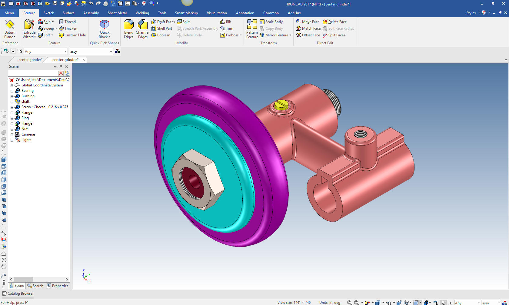
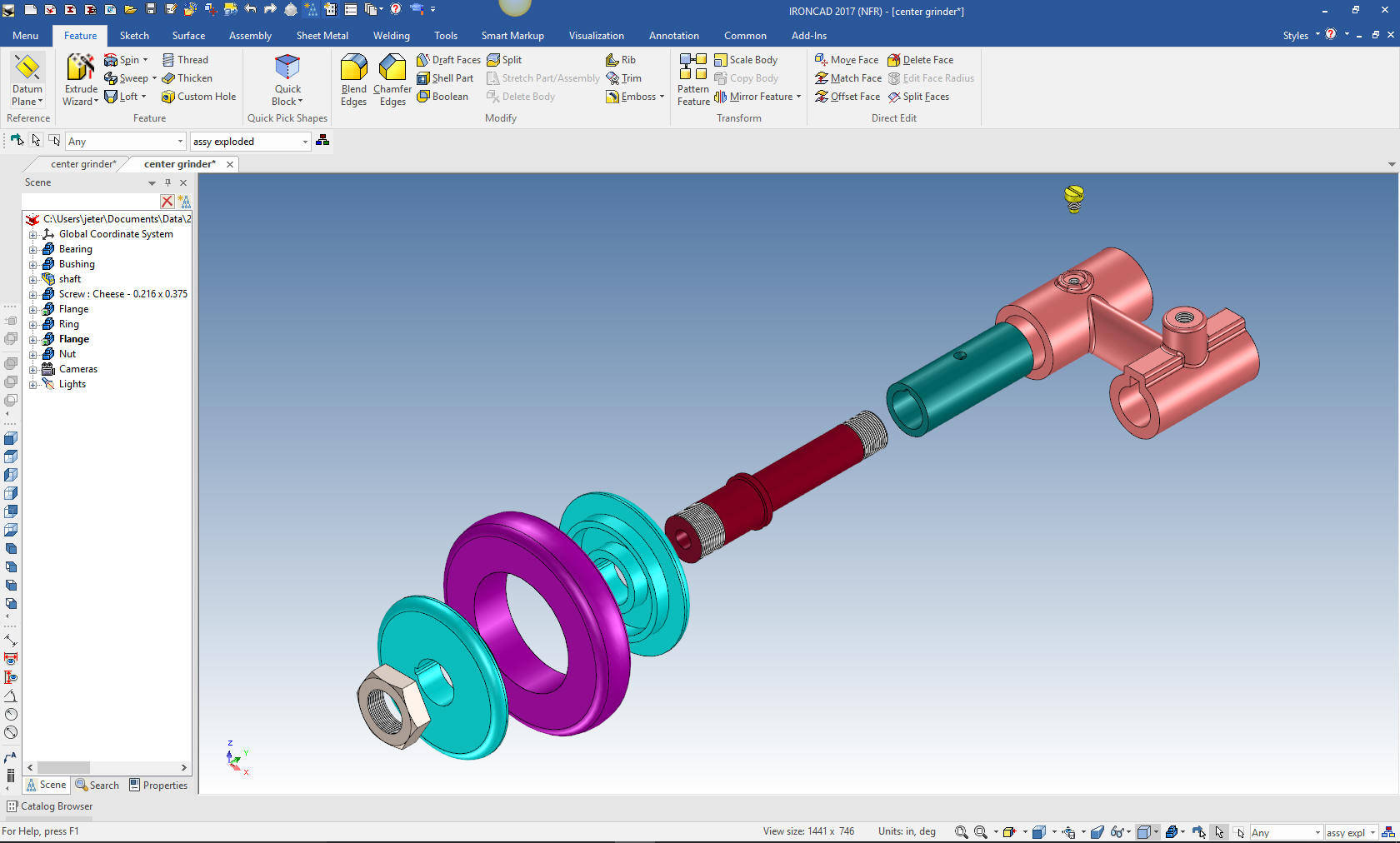
We have a couple more parts to add to our assembly. The true
single model environment is by far the most productive feature in 3D
CAD. Watch how easy it is to design parts in context or top down.
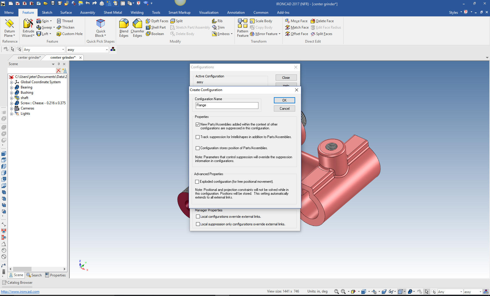
We are going to model the Flange. First we create a
configuration called "Flange". With a single model environment
this is how you differentiate the parts for detailing and viewing
assemblies. You can have any level of configuration. This is much
better than using levels as it is done in other single model
environment programs.
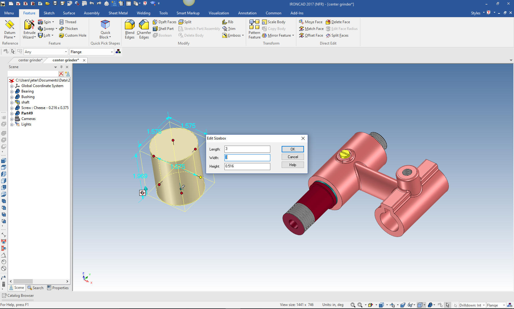
We drag and drop a cylinder into the
design scene and we size it. I could do this in context but there
are not enough matting edges to make it worth while and, of course,
it is very a simple part.
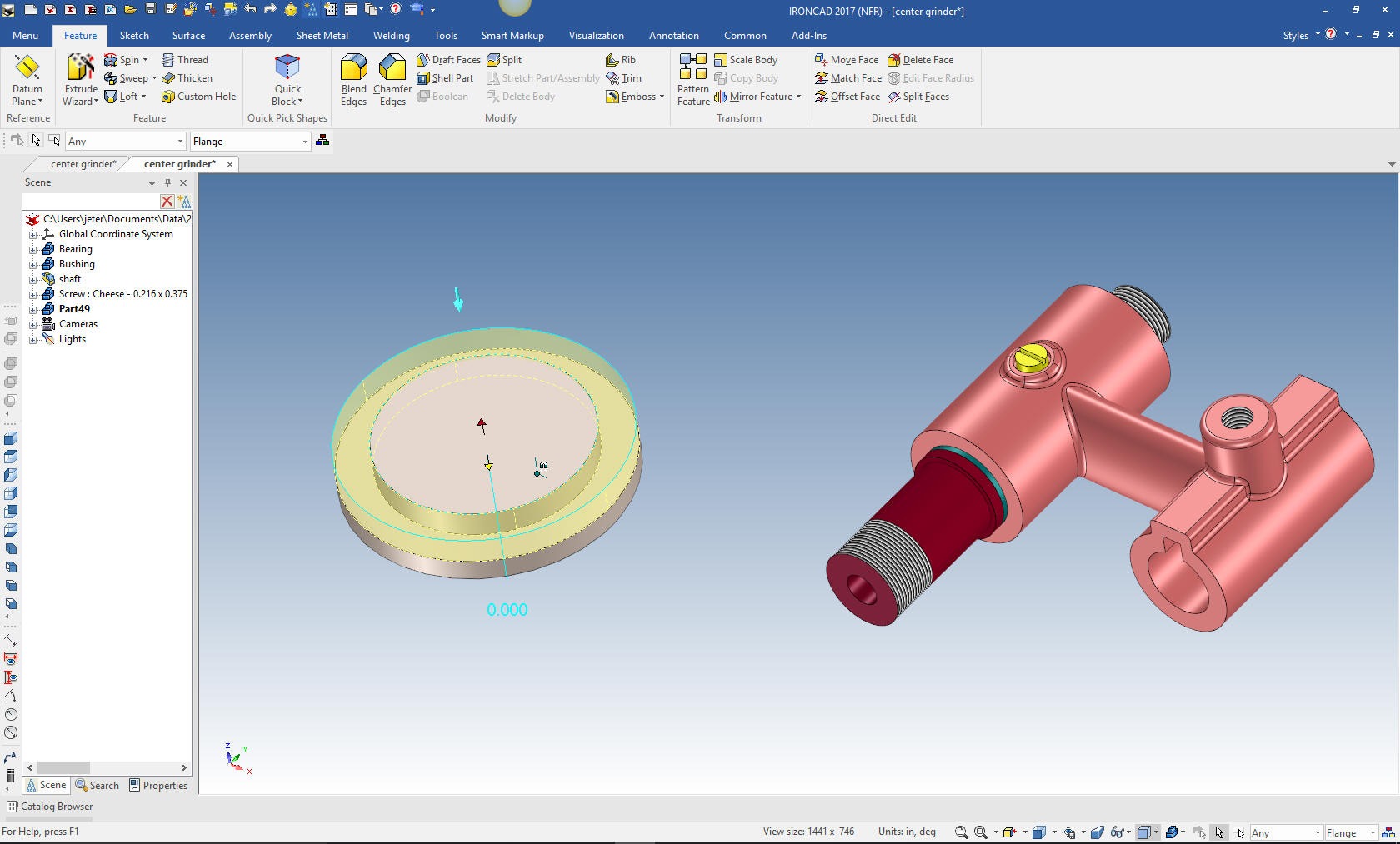
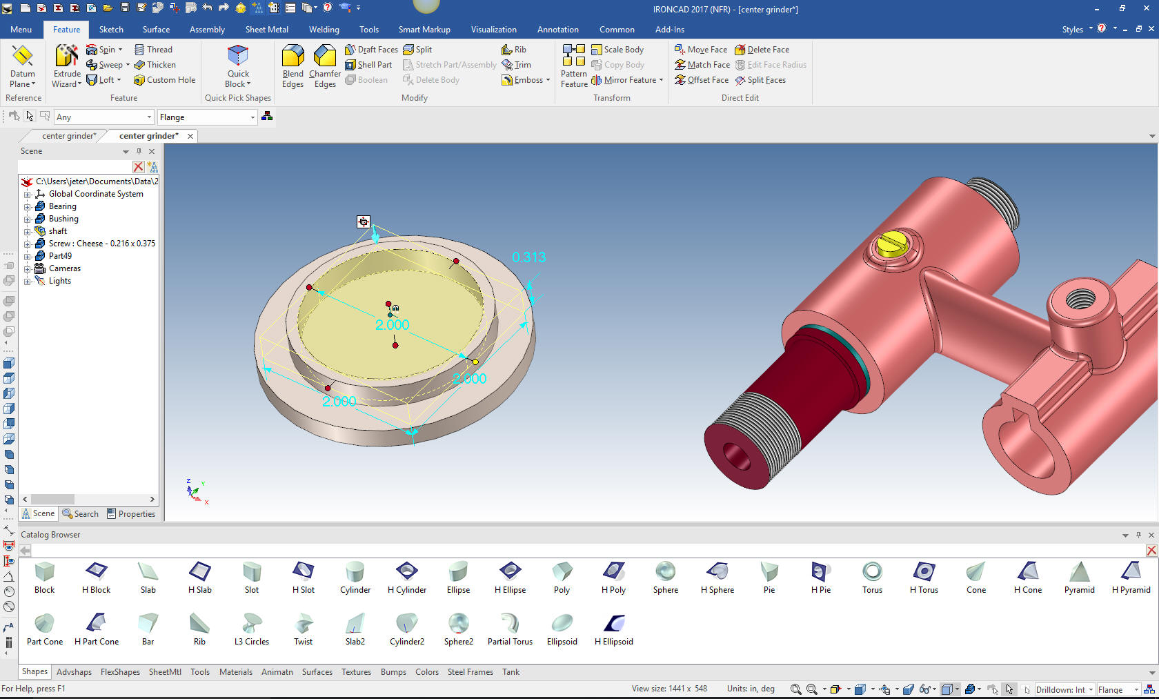
I could do a sketch only, but I will do a
mixture of drag and drop and sketching. To make the outside cut I
will use the extrude wizard. I will insert a plane on the affected
face and set to remove. Project the outer edge and create the inner
circle of 2.25 diameter then select okay.
We drag and drop a hole cylinder to the center of the existing face
and size 2.00 X 5/16
We
drag and drop a cylinder to the center face and size it 1 3/16 X
3/16
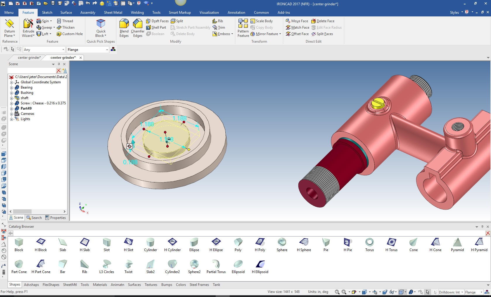
Now we just drag and drop a hole cylinder on to the center of
boss and size it.

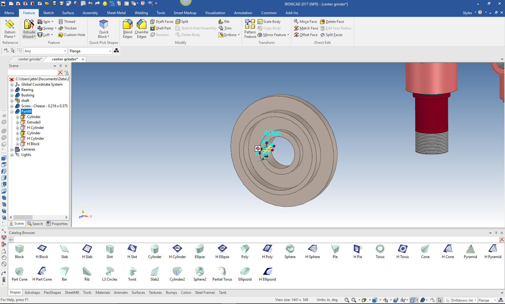
We now
drag and drop a hole block on the the face, located it and size it.
As you can see the difference between feature modeling as compared
to sketching.
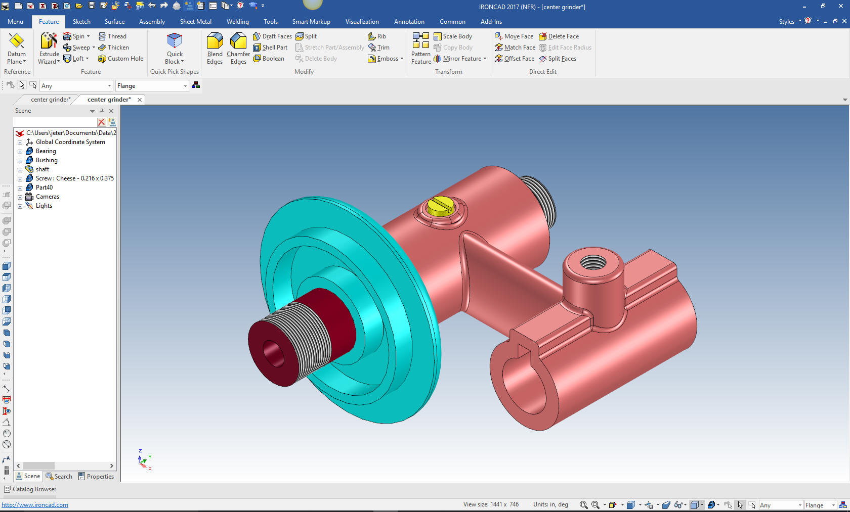
Last we will put move the Flange to the
correct position with the triball and add the blend, change the
color and we are done with the part. We will suppress the other
parts so the Flange will be the only part in the configuration.
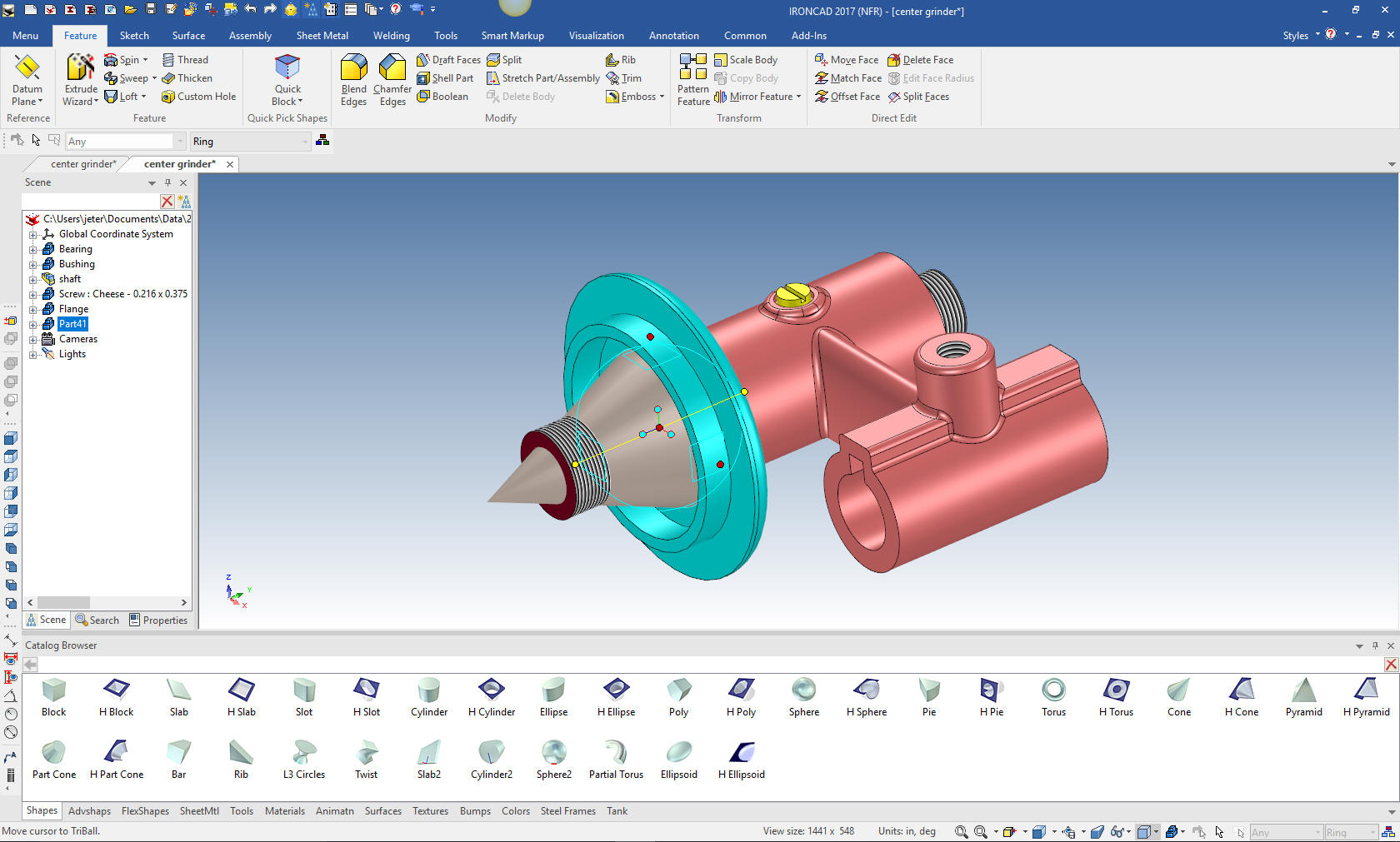
We will now model the Ring. We will create a Ring configuration and
unsuppress the other parts for reference. I will drag and drop a
cone on an existing part using the right mouse button. This gives me
the option to create a new part or a feature on the existing part.
We will create a new part. I do this eliminating the need to set it
up trough the Spin Wizard. All of the shapes are based on a sketch.
I just edit the sketch and I am done. I thought of this concept a
few years ago. IronCAD opens doors to modeling techniques that are
beyond the Solidworks clones.
I
select the cone at the feature level, using the triball, rotate the
sketch to the orientation I want to work. You can see the graphics
that make up the cone.
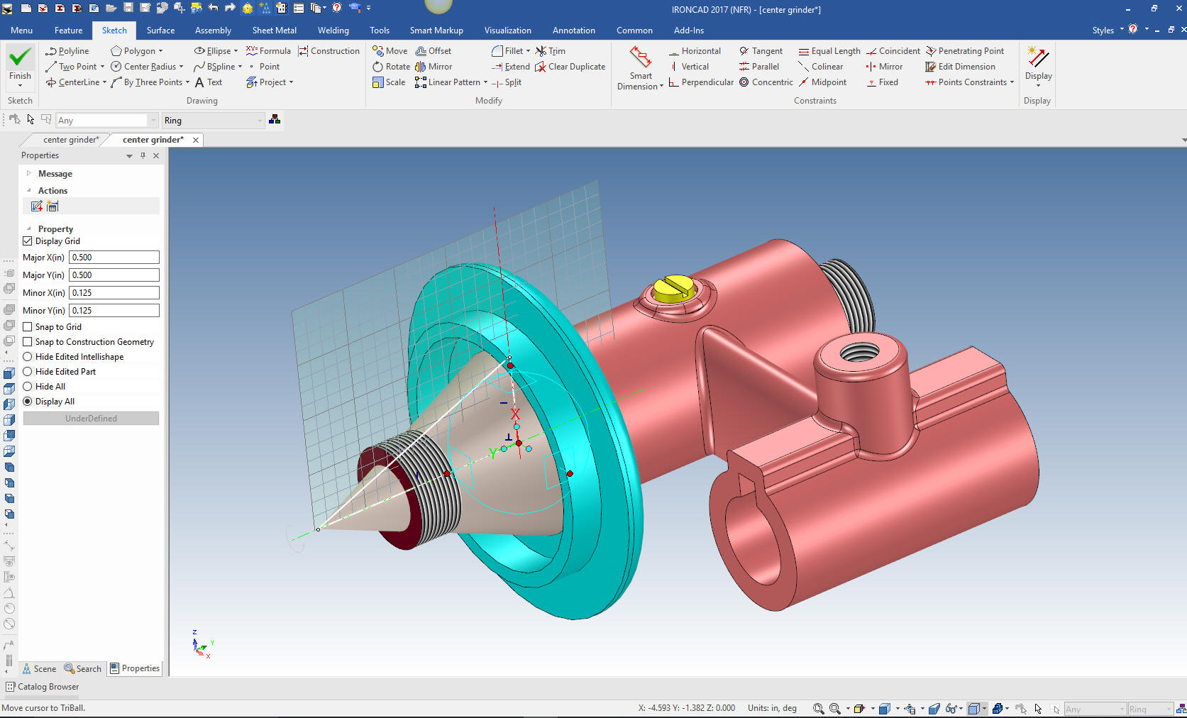
I
will now sketch the ring in context in the part location. Using the
cone I do not have to set any parameters for the spin. I just select
okay and we have our ring.
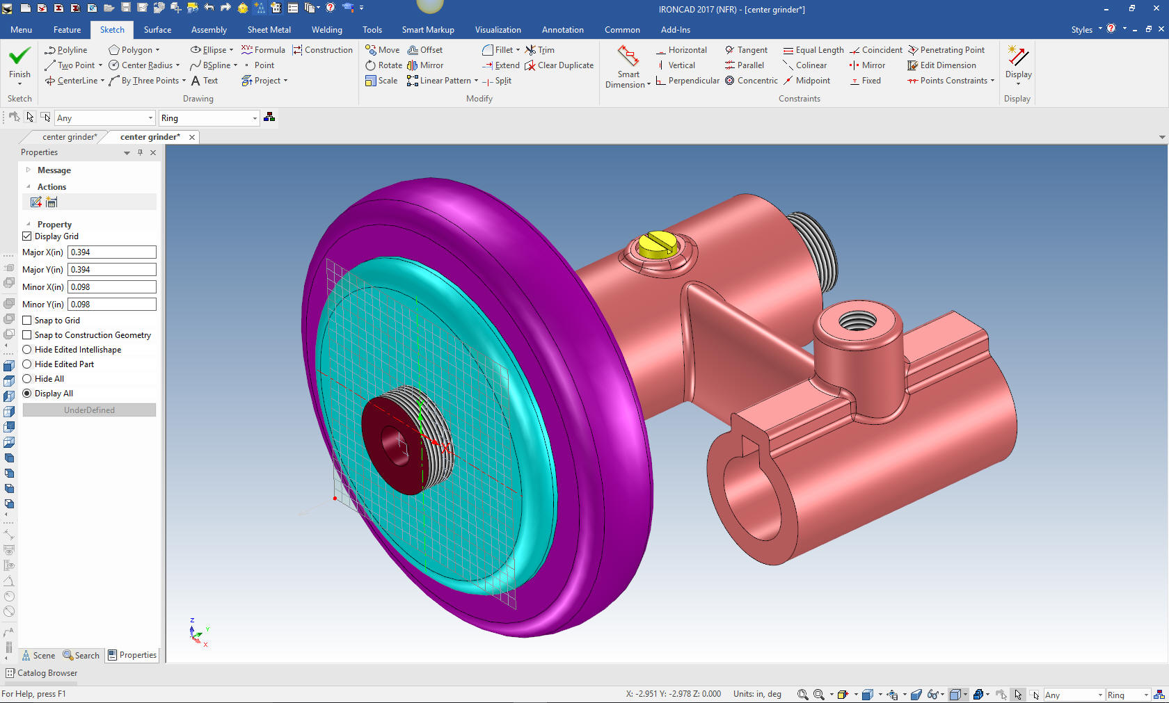
I add the blends and name the new part Ring. I mirror and link
the Flange. Linking creates an associated duplicate of the part that
can also be used when creating the parts list. I suppress everything
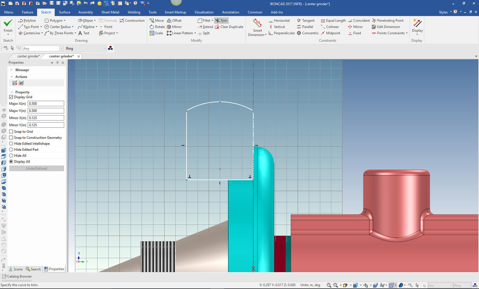
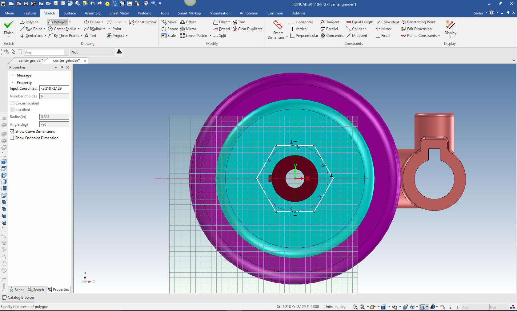
except the ring and create a new configuration called the Nut. I
unsuppress the other parts for reference. Next, again using the
extrude wizard selecting the stand alone part option, we create a
plane on the face of the matting part to create the Nut. While we
have a primitive polygon we can drag and drop it does not give us
the options we need to create the unique nut.
Using
the Look at tool I will look directly at the new sketch, select the
polygon tool in the sketch menu and define the Nut.
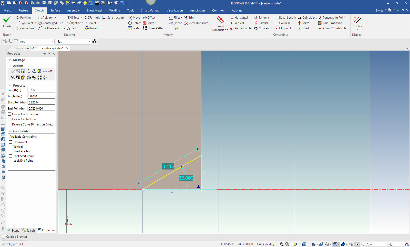
We
select okay. Now we need to create the chamfer. This time I drag and
drop a hole cone onto the center of the nut, then edit the sketch. I
always think I am so clever when I use the cone.
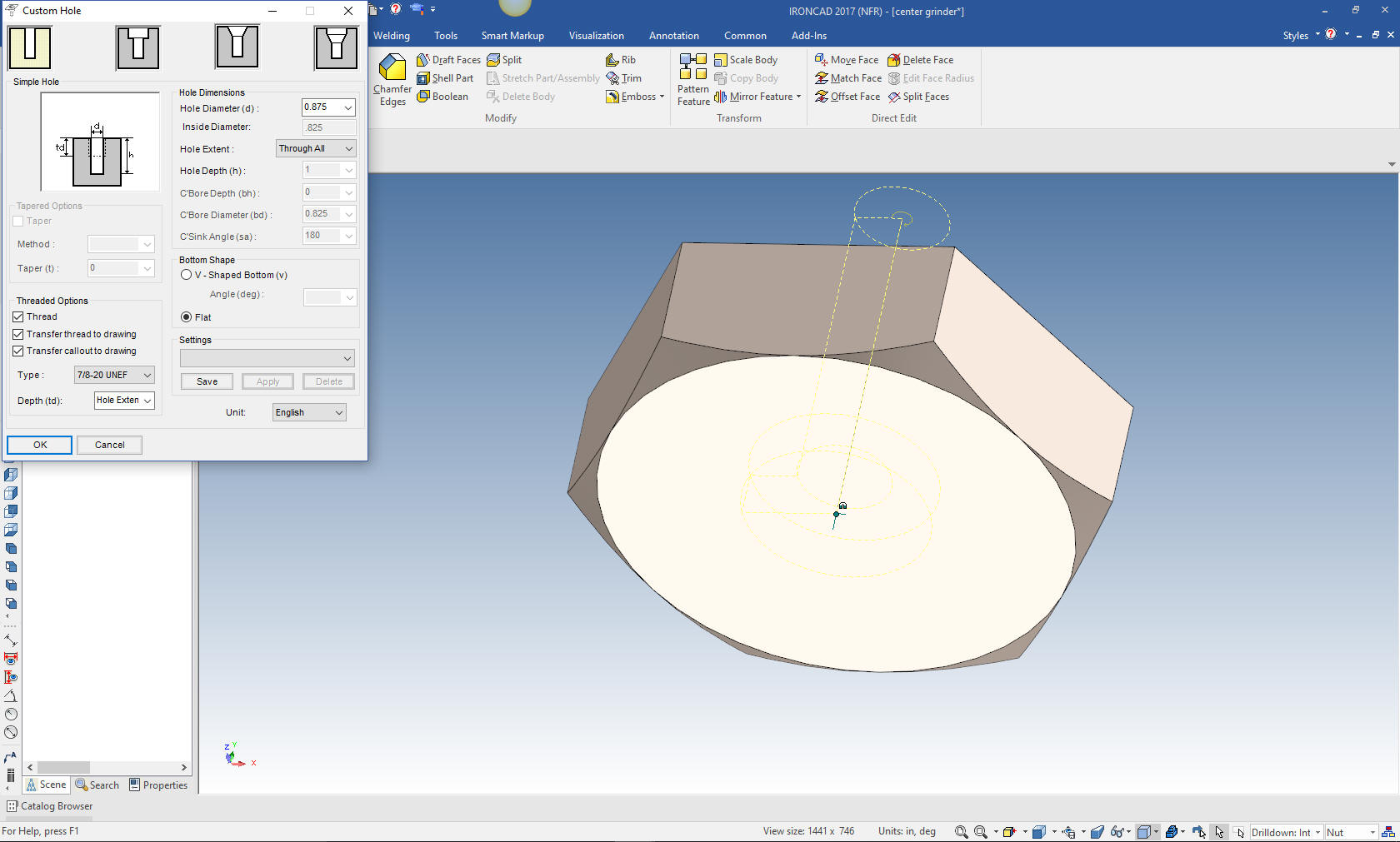
We
will name the part, and suppress the other parts and create the
treaded hole by dragging and dropping a custom hole from the tool
catalog. Standard and custom Catalogs offer an incredible level of
flexibility and productivity. Just imagine all of your common parts
at your fingertips to utilize.
We are
done with our modeling. I will create AIDs (Associated Information
Documents) (drawings) for these new parts.
We
can use the existing exploded view to move the other parts into
place with the triball.
I am
going to detail these parts in one sheet. Ironcad allows all of the
parts to be detailed in one document. Great for one person doing an
assembly.
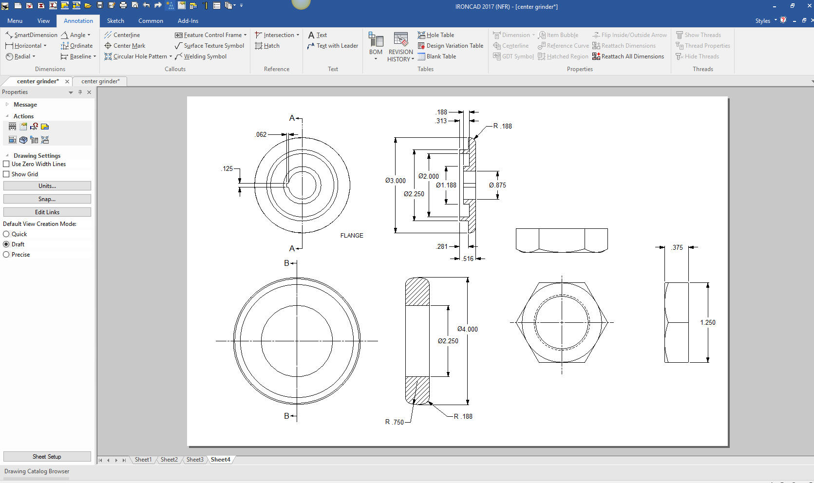
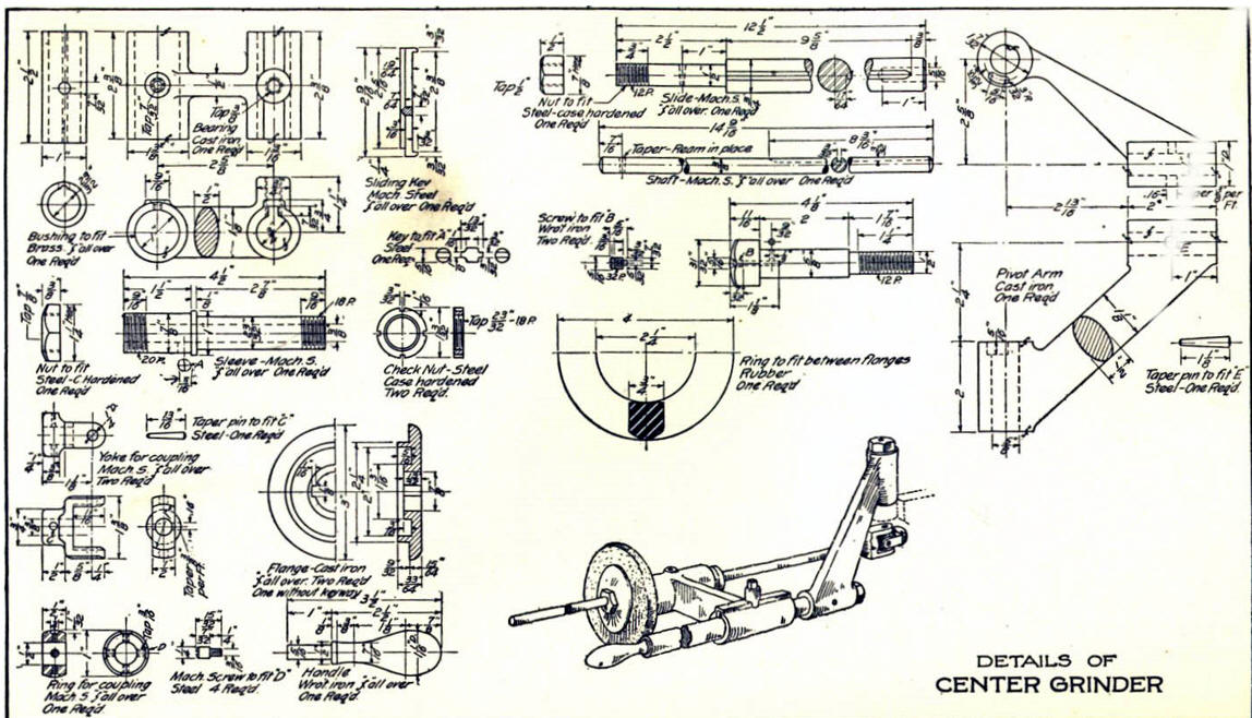
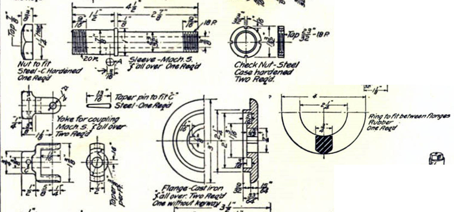
Here
is the original. I did add some dims that were not defined.
Now for lesson Four:
3D Modeling Techniques IronCAD Lesson
Four
If you would like
to try IronCAD, please download for a 30 day evaluation.
For more information or to download IronCAD
Give me a call if you have any
questions. I can set up a skype or go to meeting to show this part
or answer any of your questions on the operation of IronCAD. It
truly is the very best conceptual 3D CAD system.
Joe
206-842-0360
TECH-NET Engineering Services!
We sell and
support IronCAD and ZW3D Products and
provide engineering
services throughout the USA and Canada!
Why TECH-NET Sells IronCAD and ZW3D
If you are interested in adding professional
hybrid modeling capabilities or looking for a new solution to
increase your productivity, take some time to download a fully
functional 30 day evaluation and play with these packages. Feel free
to give me a call if you have any questions or would like an on-line
presentation.
|