3D Modeling is the basis for our
engineering. That is the only place where productivity is paramount.
You can have all the PLM/MBE gurus debating data management, but it
does not add one smidgeon of productivity to the design process.
Top down or In-Context modeling is
the most productive feature of 3D CAD. Most systems tout this but
each part is still an external part. We are talking about a single
model or multi-object design environment. Both of the systems we
represent offer this as the "normal" design process. Thereby
increasing your productivity 20 to 30%.
In these exercises I not only focus on modeling techniques, but
also on much more productive systems to do our designs. I hope you
enjoy them and learn something. If you are in management, understand
that all 3D CAD systems are not the same. Cutting your engineering
costs is very simple. Even your legacy data is not a problem. Please
feel free to give me a call. There are millions of man hours wasted
every day with poor modeling techniques and ineffective 3D CAD
systems that cost a fortune. Productive 3D CAD systems do not have
to be expensive.
Joe Brouwer
206-842-0360
I am
doing the below assembly for an exercise showing my modeling
techniques and, of course, our superior 3D CAD
solutions.
I saw the
some video challenges on linkedin and thought I would
give it a try on IronCAD. I got a great response and decided to do
it in ZW3D. I was very familiar with the parts and it was a bit
easier.
These exercises started out to show the benefits of
ZW3D over Fusion 360, but
quickly turned into a study of modeling techniques. Take a look at all of
them, they will open your eyes to a much different and more productive way of
modeling. It really has more to do with modeling technique than it has to do
with the 3D CAD systems. I have found that I do 3D modeling as compared to
the conventional 2D sketching. Of course, having a more productive 3D CAD
system doesn't hurt.
See the comparison with many other 3D
CAD systems.
3D CAD Modeling Techniques
ZW3D is very similar to the Pro/e
clones with a few small differences. It is very easy for those users
to get up and running with ZW3D. It has a few operation that
are a bit more streamlined. The benefits over the other systems
are the multi-object environment (top down design) with the integrated drawing. You can
do parts, assemblies and drawings in one file.
These exercises were incredibly
popular and I thought I would follow up by showing more examples of
this 3D modeling technique.
We will be doing a
couple of parts each weekend in both IronCAD and ZW3D. I hope you
enjoy these exercises and hopefully they may lead to increasing your
productivity.
Please review lessons:
3D Modeling Techniques ZW3D Lesson One
3D Modeling Techniques ZW3D Lesson Two
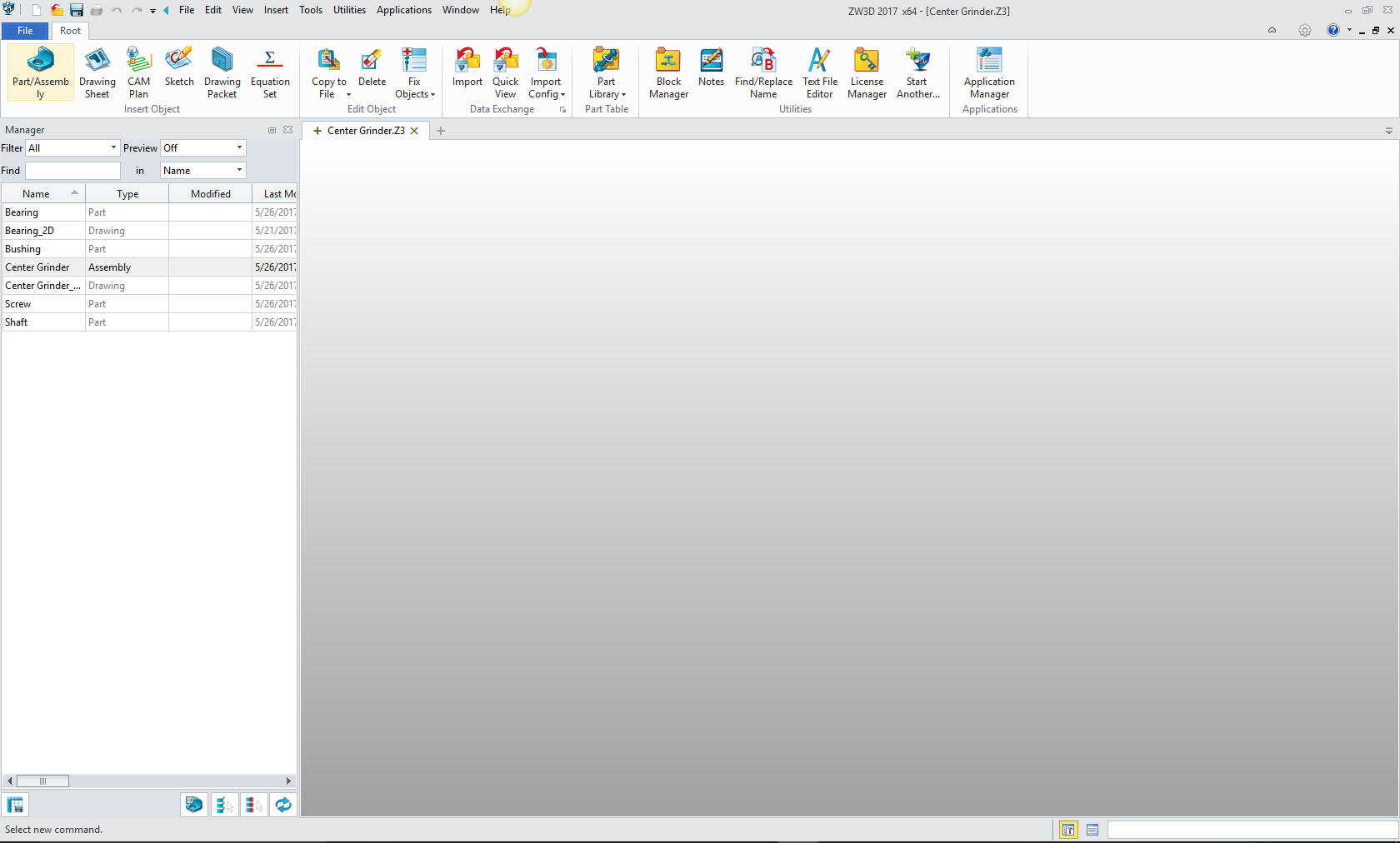
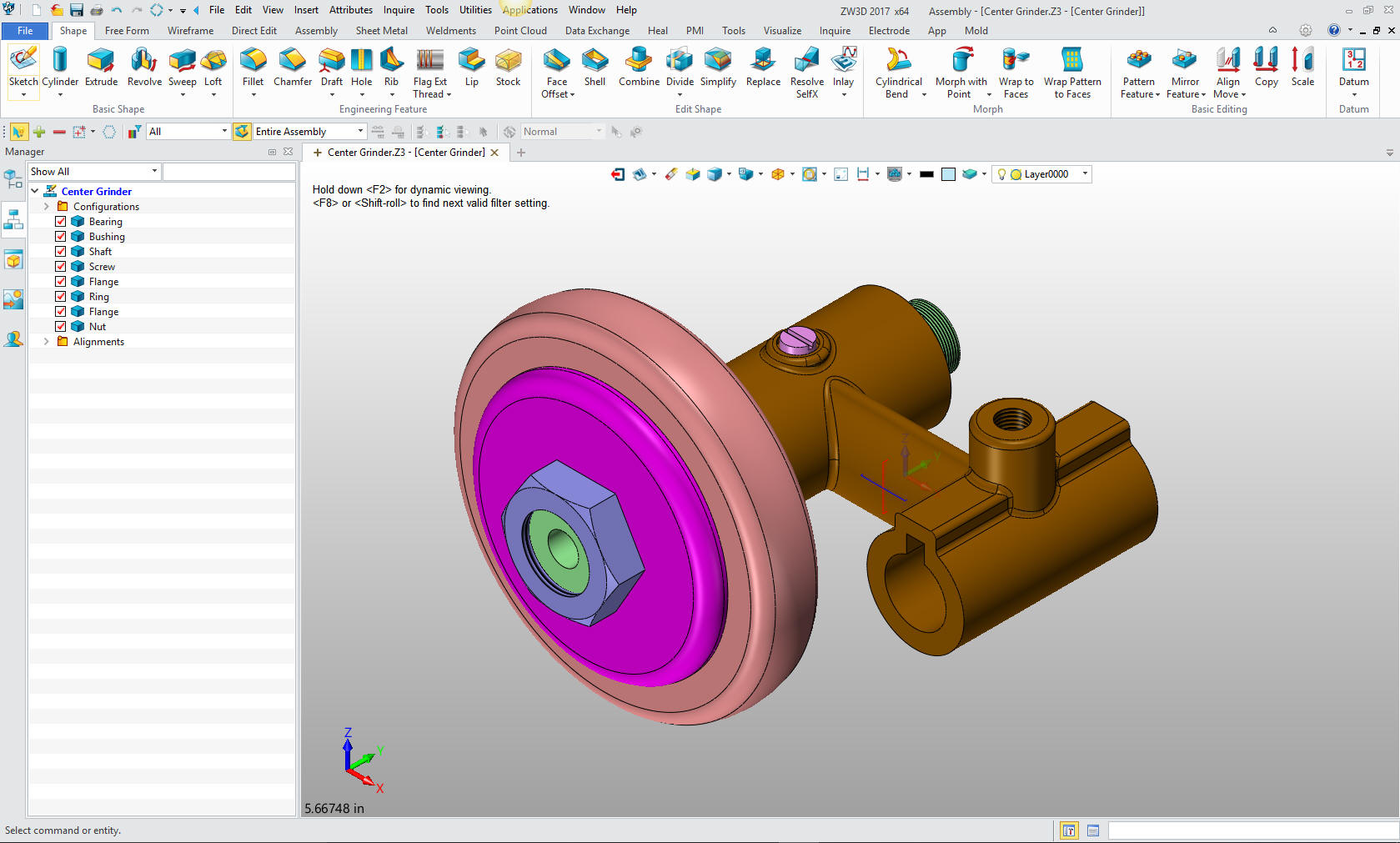
We will bring up the Center Grinder file:
Since we created this file as a multi-object the ZW3D Manager
automatically comes up. It shows the assembly and all the component
parts to this point.
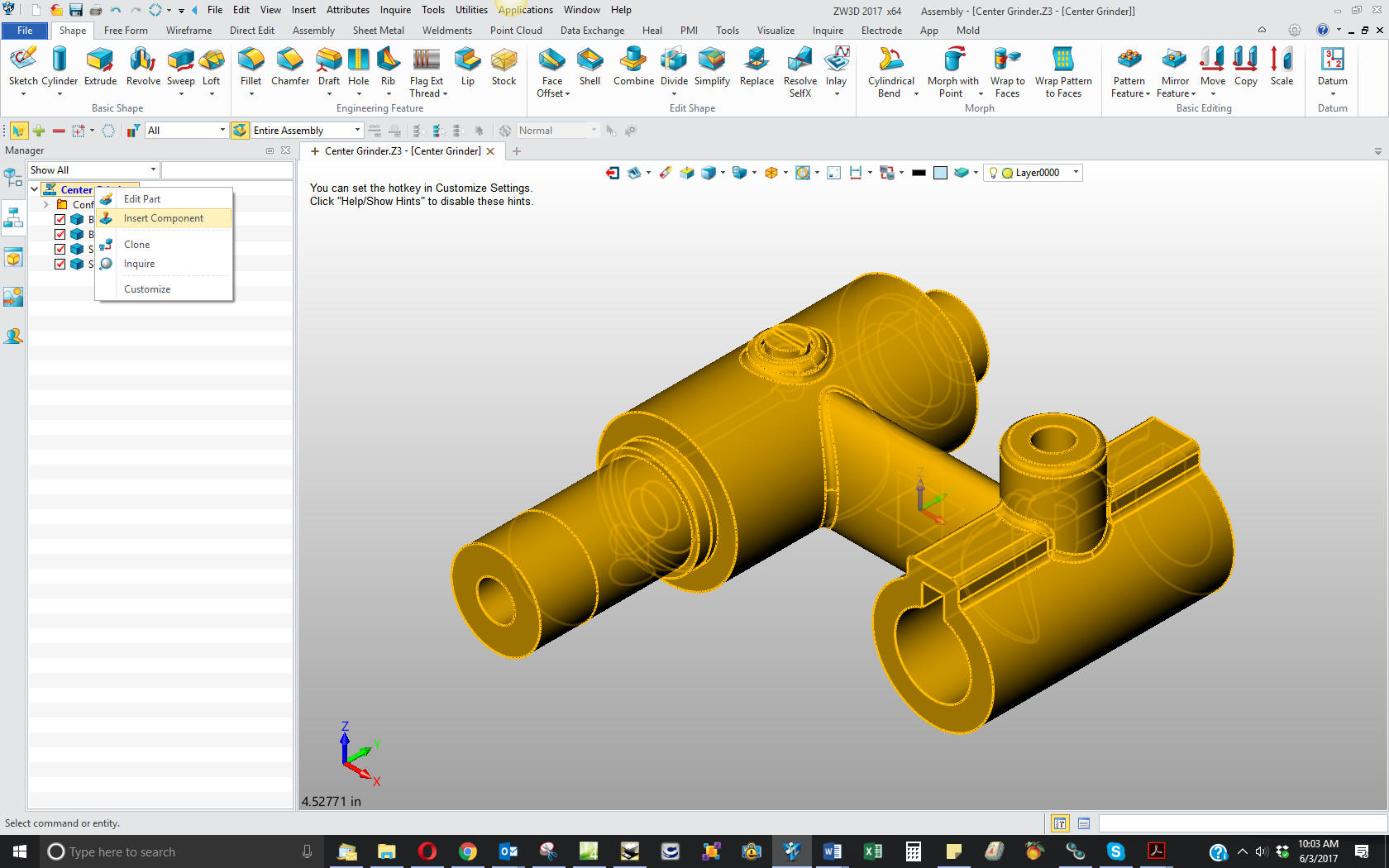
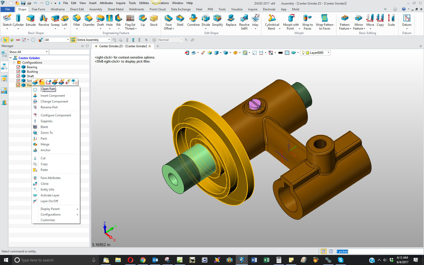
We will select the
center grinder assembly and we will see the existing parts. We will
right click on the Center Grinder assembly and select "insert
component". Again I want to reiterate this is not a true single
model environment. Each part is still like a external reference
except that it resides in the same file.
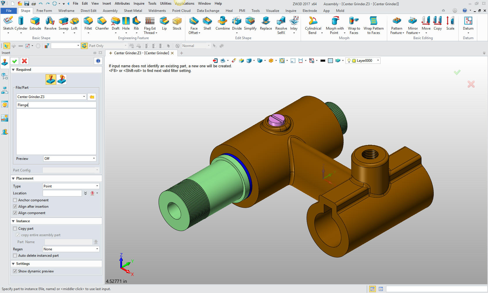
Now we
insert the Flange as a new part.
Note: ZW3D's Multi-Object
top down design is an incredible time saver. Especially for the
individual design. Which is most of us. Even in large companies a
designer is given a sub-assembly to develop.
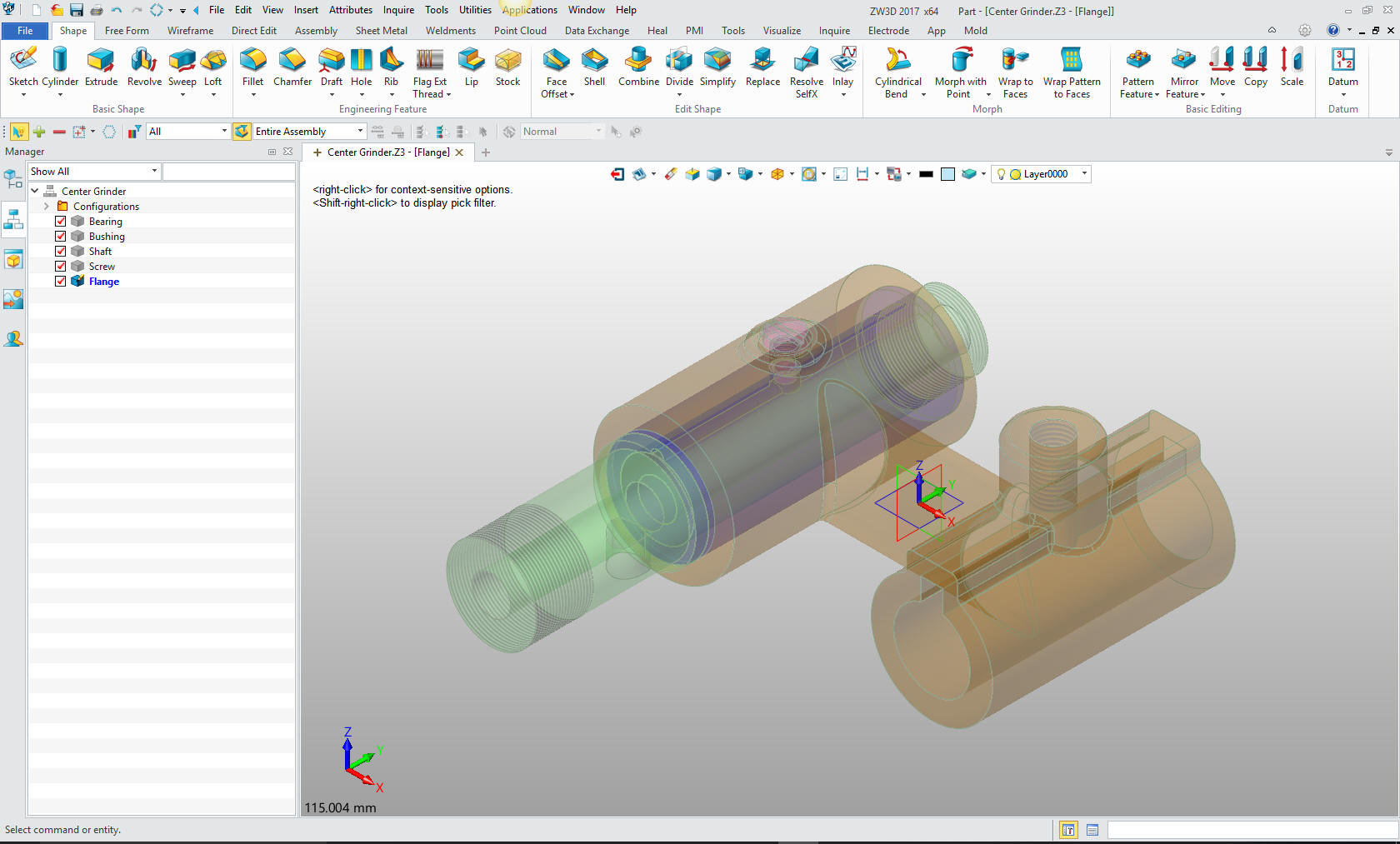
This
step automatically puts us in the "edit part" mode that shows the
other parts as ghosted. They are available for reference as you
will see. We also have the "open part" mode which has only the
single part available. You can make these external individual parts
as required.
Note: I have surprisingly found that ZW3D is a
superior top down design program. I have worked with many top down
design packages (There are only 4 that I know of) and ZW3D is
incredibly productive.
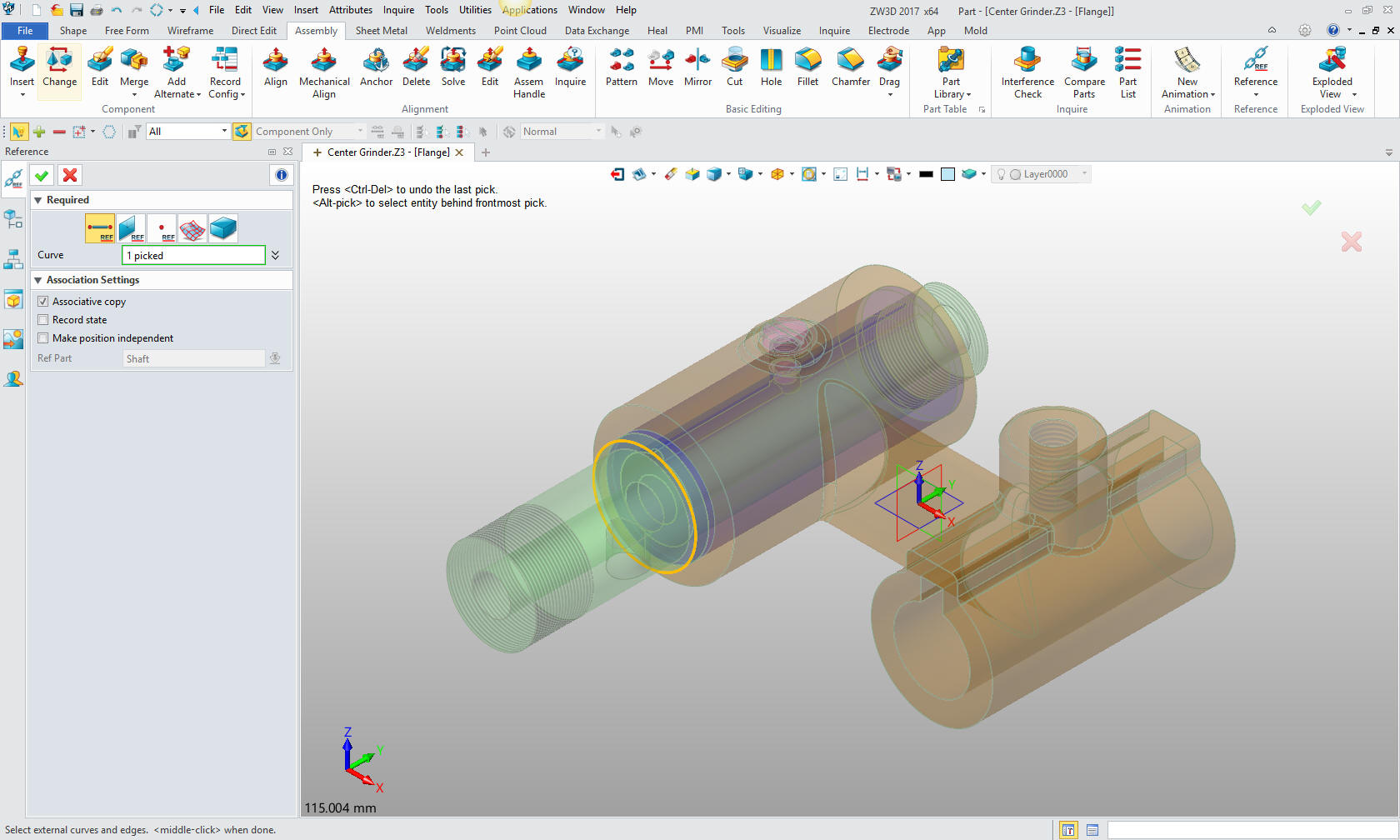
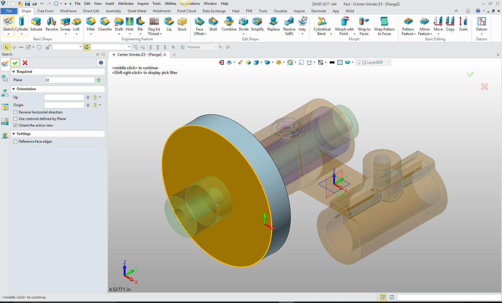
Now
will will begin on modeling the Flange. We are going to design in
top down or in context design. We will go to the assembly menu and
reference an edge.
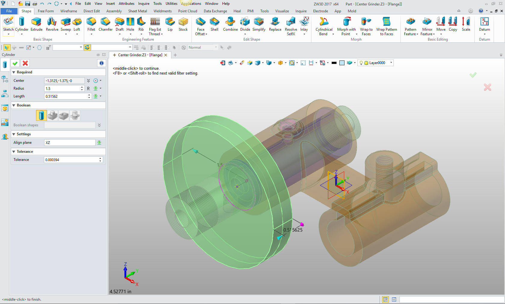
We now
insert a primitive cylinder using the center of the reference
entity.
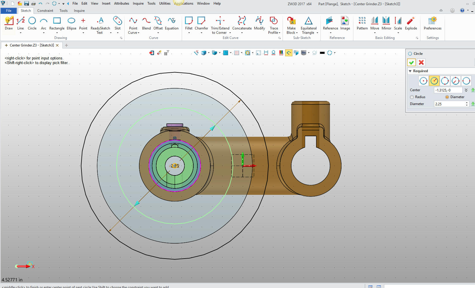
We
will create a sketch for the next cut. We will select the face of
the cylinder to establish the plane.
Now we
create the two circles, the outer circle is arbitrary just as long
as it is outside the diameter of the original cylinder.
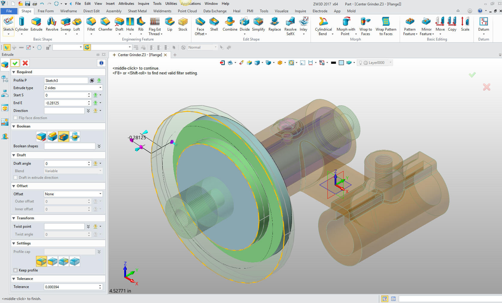
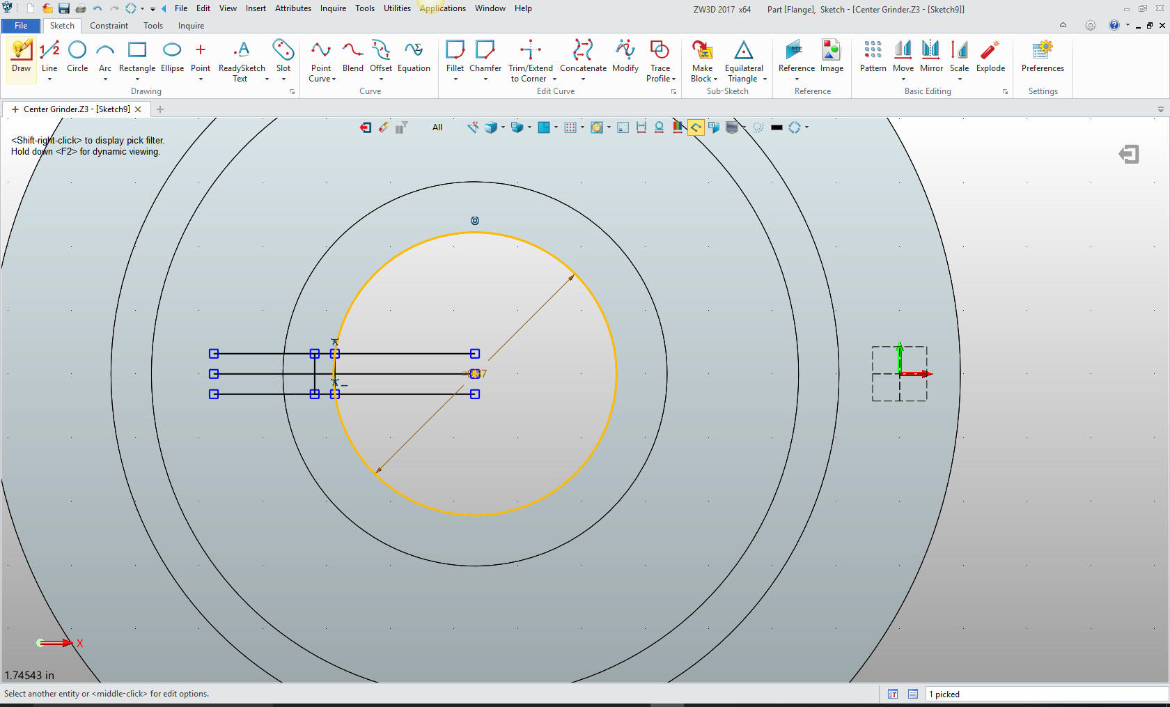
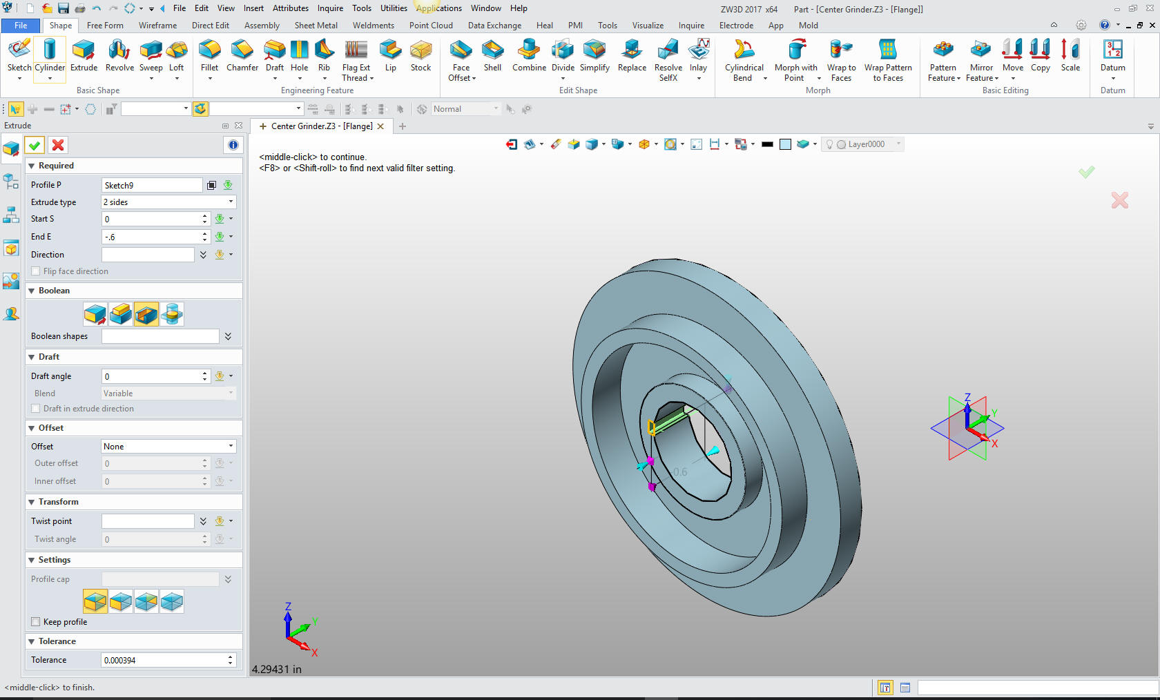
We
exit and extrude the profile.
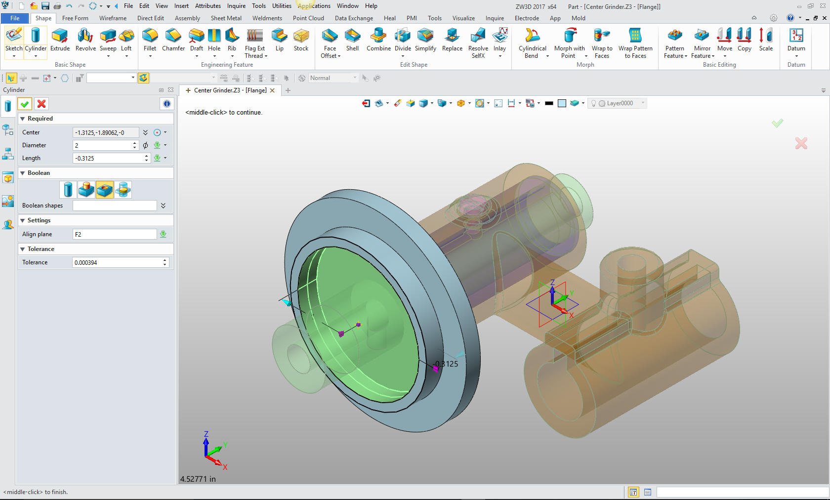
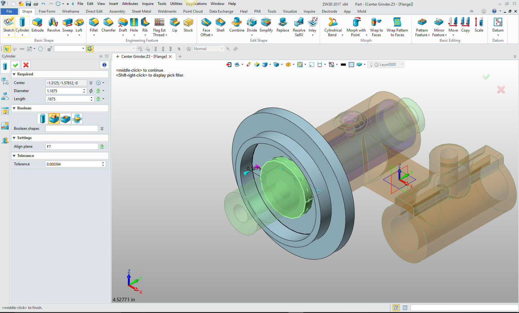
Now
for the next cut, again we insert a cylinder at the center of the
new face.
Now
for the inside boss. We insert a new cylinder on center of the new
face. If it wasn't for the primitives I would probably not enjoy
working with ZW3D as much. But this functionality makes it much more
productive.
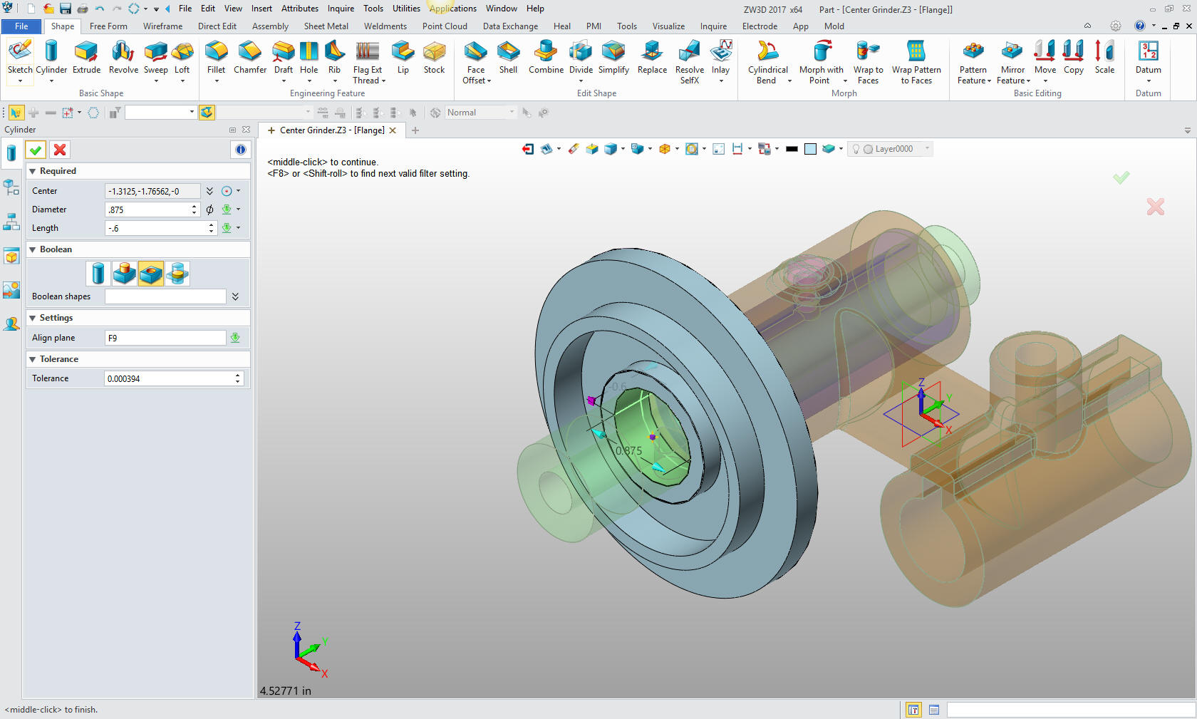
Now
for the hole. The use of Primitive cylinders is incredibly simple. I
use this type of design to show those that are in the sketch,
sketch, constrain, constrain only world there is another highly
productive way of modeling to add to your modeling arsenal and
increase your productivity, offering a more pleasant design
experience. It is much more fun.
Now
for the slot for the key. I could insert a block. But locating them
can be a bit tough in certain conditions. This is one of them. It
would just cause too much thinking. Years ago I realized that there
were certain ways of design that took too much thinking. I found
that with the Solidworks clones. We want a system that does not
require a lot of thinking.
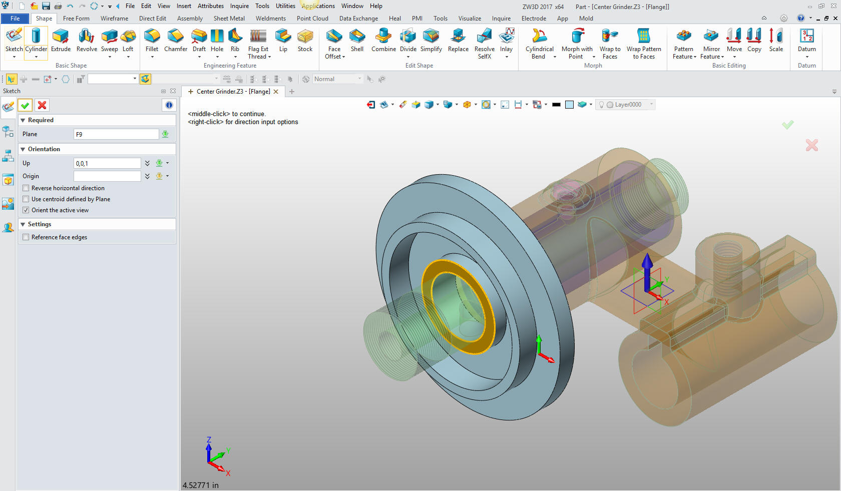
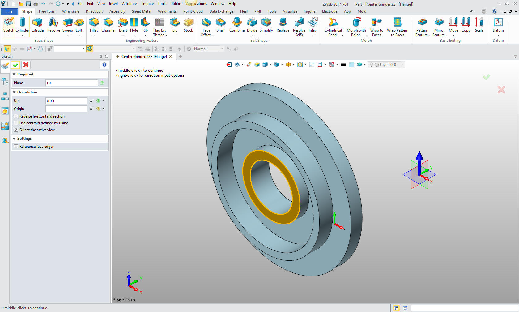
We won't think much to an sketch
the slot. We use this face to define the sketching plane. Notice the
blue arrow selected that establishes which direction is up for my
sketch. This was all new to me, very clever indeed.
I have
found it a bit difficult to find the edges I want to work with in
the sketch with the other parts shown, so I just open the part. Much
of this is a learning curve for me. But I am enjoying realizing how
incredibly easy it is to model in ZW3D.
Now I
can create the sketch on the effected face. Notice that the blue
arrow is highlighted indicating the up direction for the sketch.
Clever indeed.
We now
sketch the slot. I sketch a bit different than most of you. I use
the entities for construction geometry. Notice I created a circle to
establish the intersection to establish the right vertical line of
our slot. I suppose I started doing this with CADKEY when we were
designing in 3D wireframe. The entities, lines, arcs and spline were
actually the edges of the parts. There was no sketching as it is
defined today in the Solidworks clones.
Now I just trim or
extend and delete the entities to get our net profile.
Exit
the sketch and extrude the cut. I am doing this to show you a
different modeling technique, many of the steps can be done with
effective sketching. I am calling this feature modeling, different
from constrained sketching, and can be done with any system.
We add
the fillet and we are done with the part. We will now create the
ring. We create the plane. This has always been a mystery to me. I
am just getting used to it.
Again
you can see I sketch much differently. I create a center line and
vertical line. Then create offsets to establish the basic rectangle.
I trim the outer line so I can then use the mid point to create a
vertical line that is the radius for outer curve. No sketching or
constraining just using the existing geometry. Much Simpler?? I then
trim, extend or delete the geometry to create the net profile.
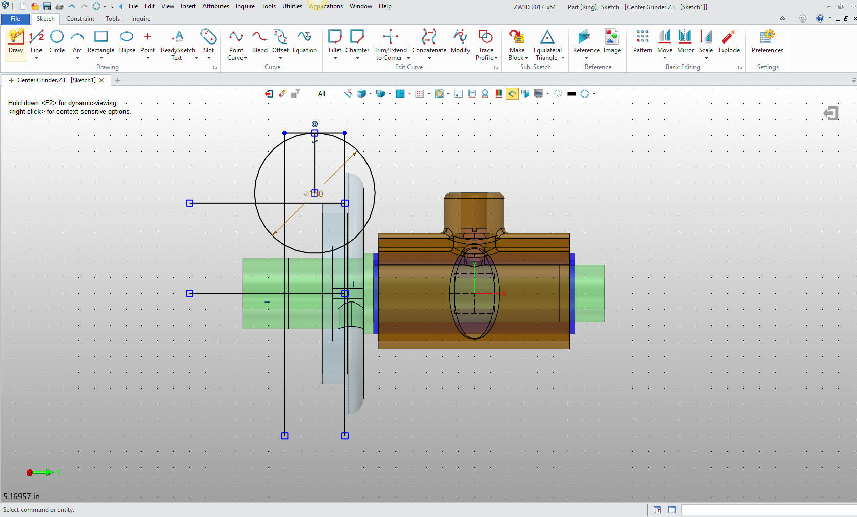
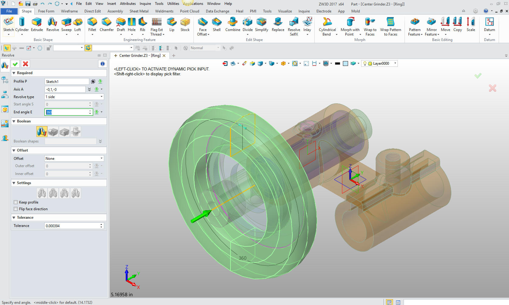
Just select the revolve command and select the profile and axis.
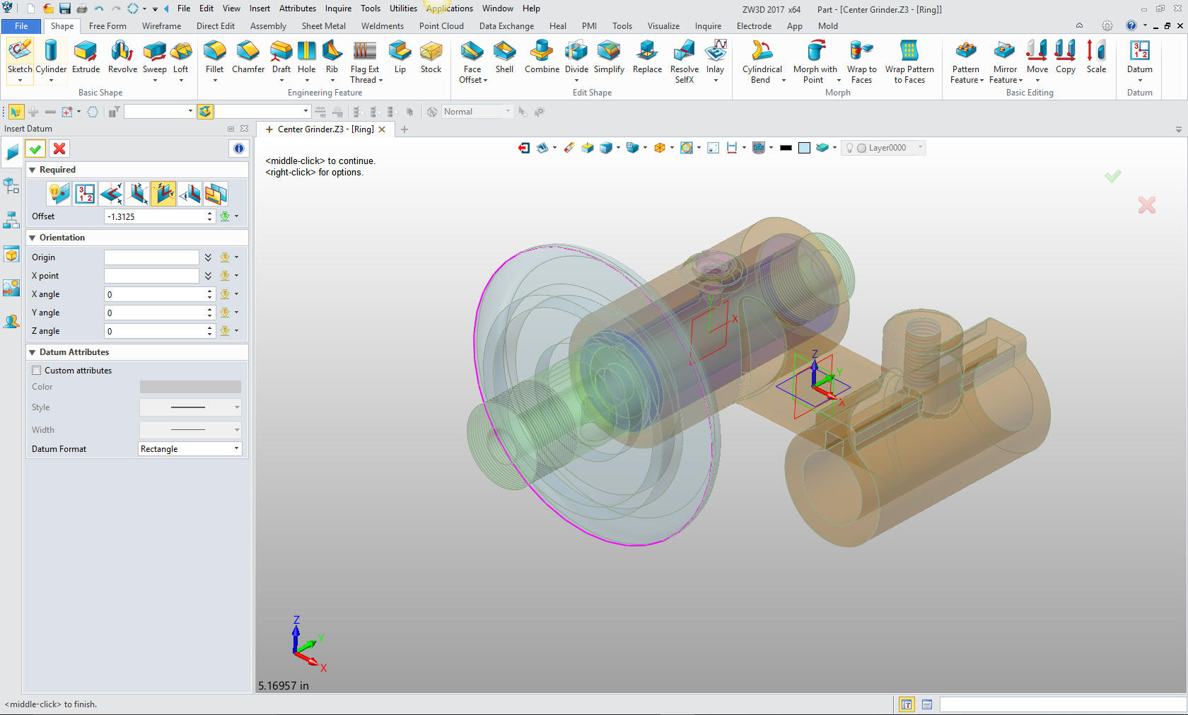
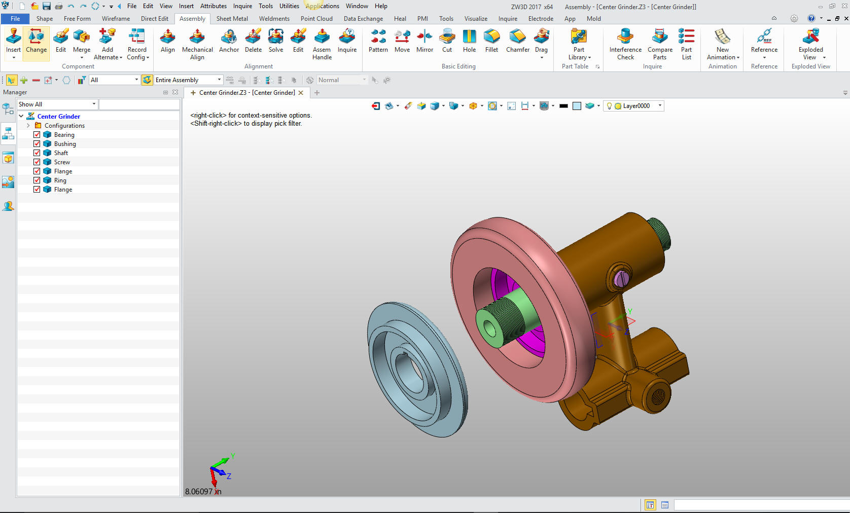
We
have two flanges so insert another flange, and move it to align it
with the ring. I have always had a very straight forward way of
doing this in IronCAD. So I had to figure this out. Alignment was
one of my other mysteries in the Solidworks clone world. They were
always inserting, aligning and constraining parts. It seemed so
convoluted, since I have always designed my parts top down. I think
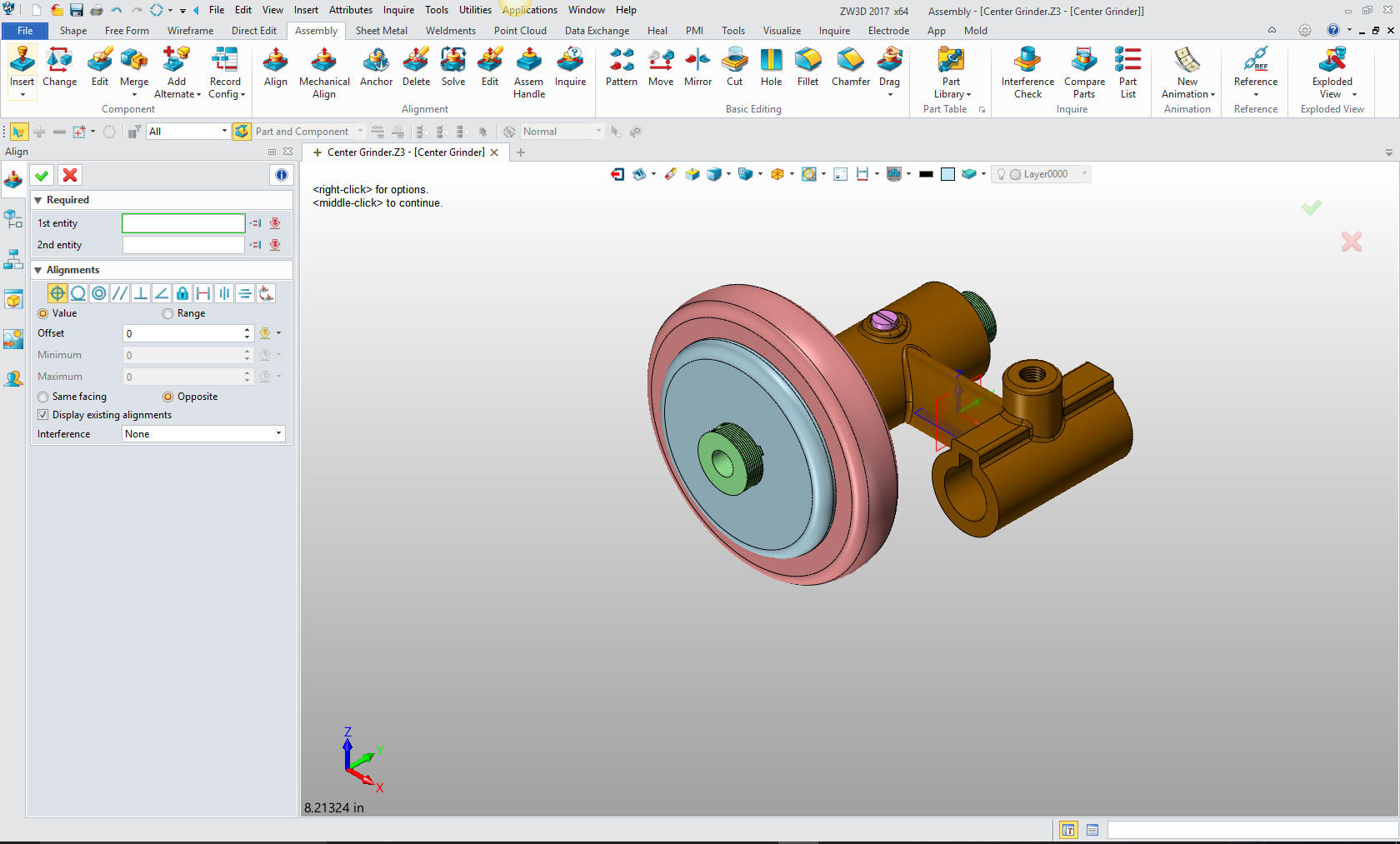
this is the first time I have inserted a component in any program.
Actually with a bit of investigation it turned out very, very easy.
I just went to the assembly menu and selected coincident align. it
was the default. I Picked the mating face on the flange and selected
the mating face on the ring. I must have done something wrong it was
that easy.
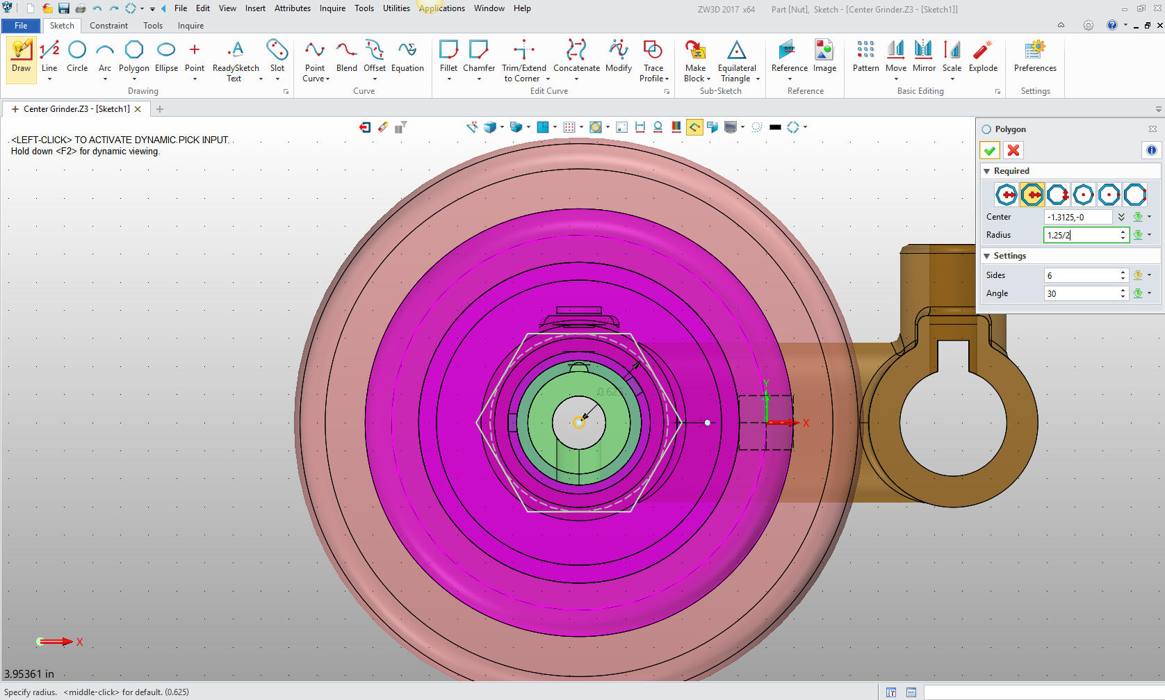
Now for the nut. We just create a plane on the face of the flange.
Had to figure this out but looks like I succeeded.
Just
select the polygon and insert in the middle and input the size.
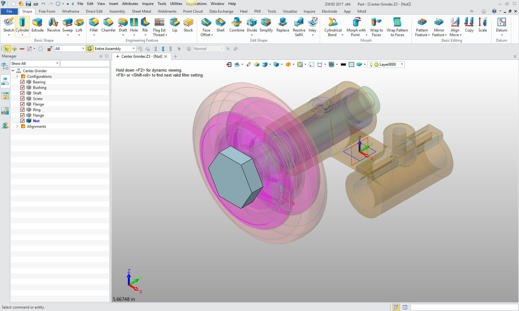
We
extrude the polygon
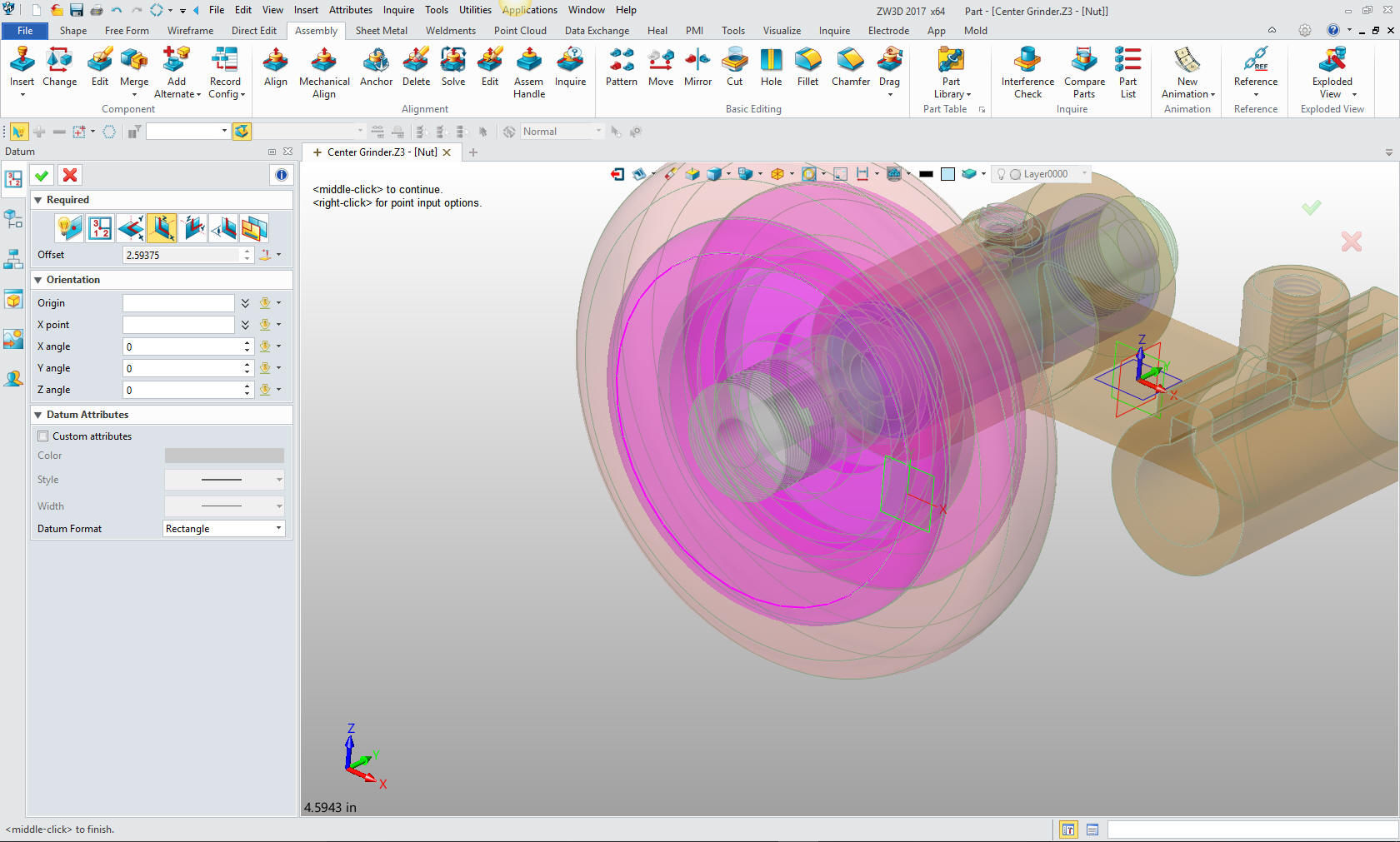
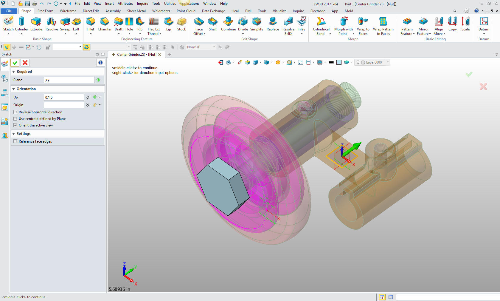
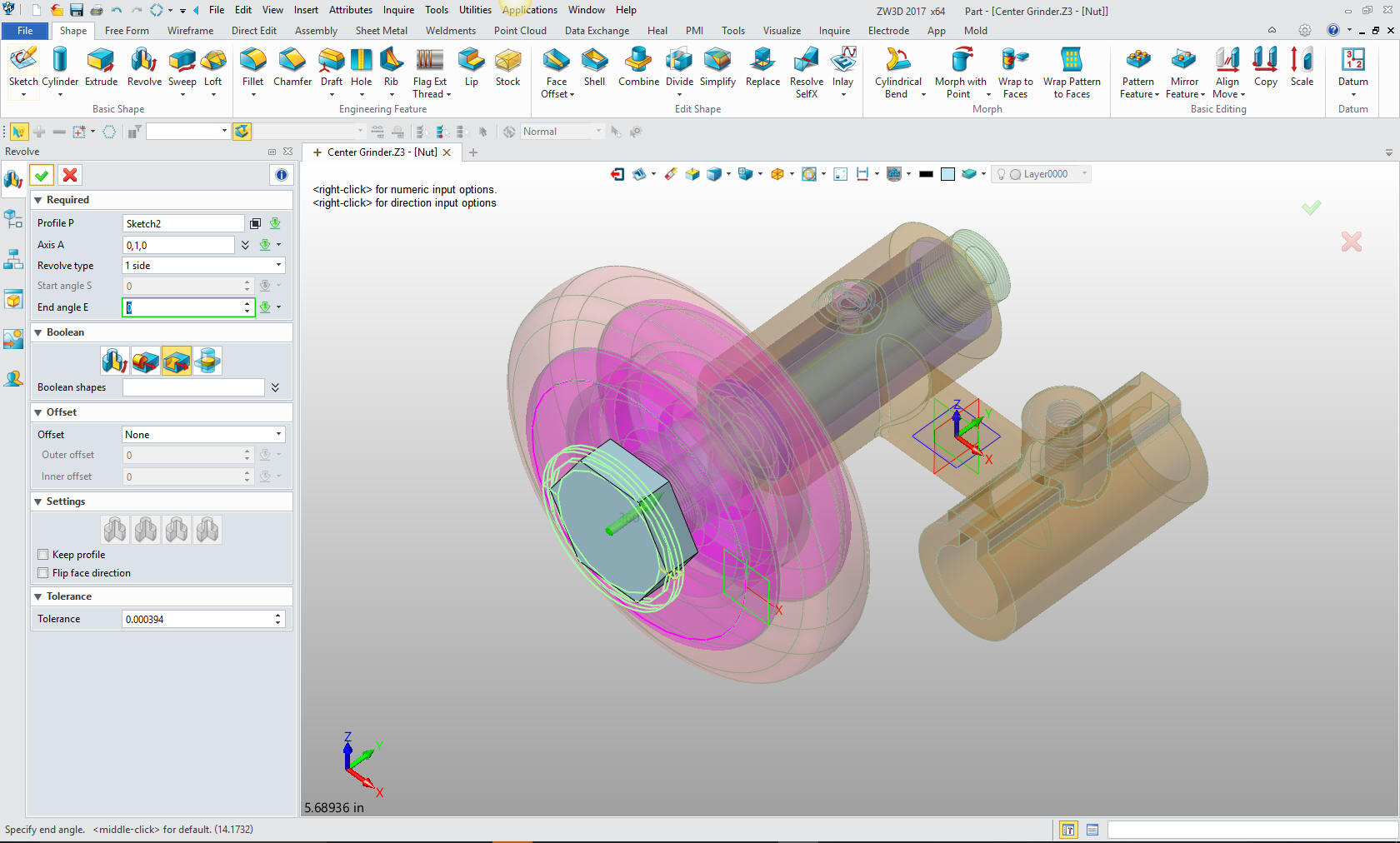
Now for the small chamfer on the edge of the nut. We create a sketch
on the XY plane.
I
start the sketch with a .625 line from the center of the nut. Then
the angled line, a vertical line then close it off with the last
horizontal line and delete the construction line. No constraints.
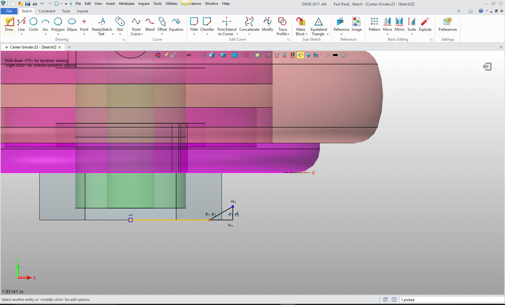
Select revolve and the profile.
Now
for the threaded hole.
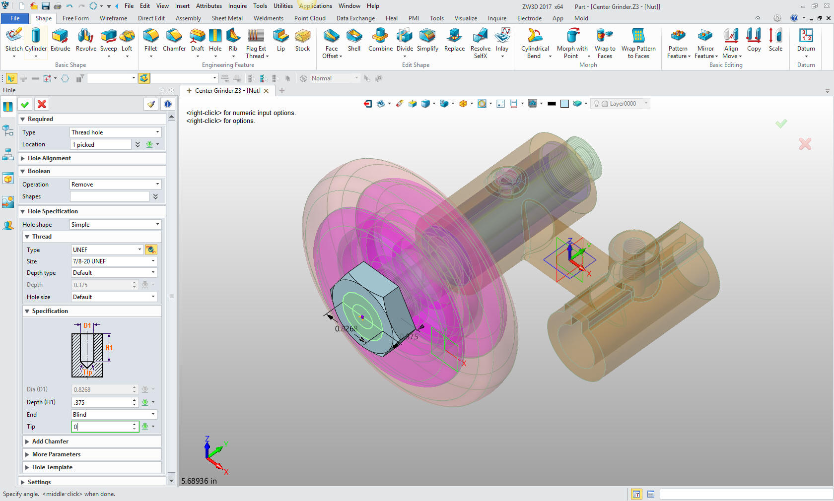
We are
now done with the parts we are doing today.
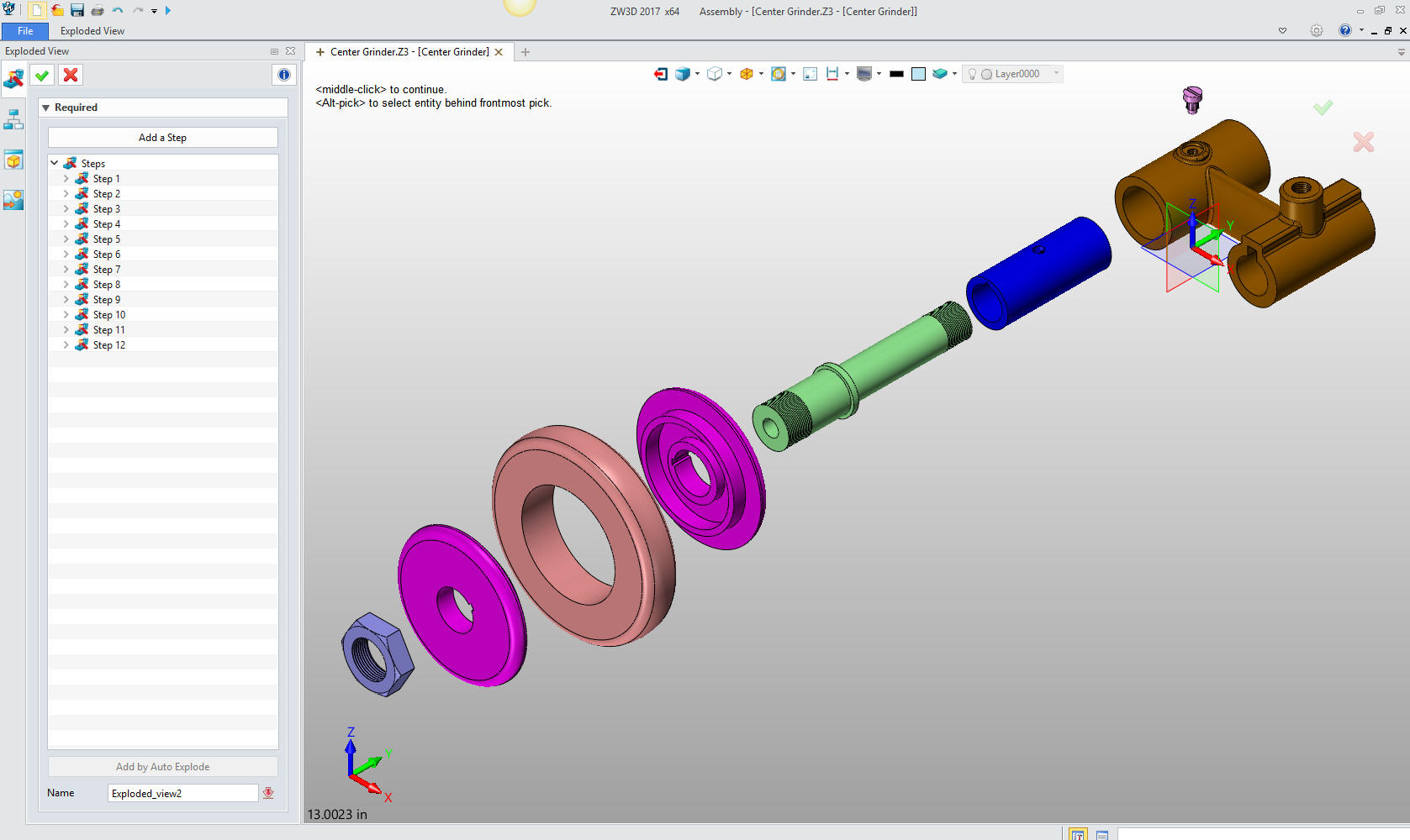
Here
is an exploded view, yes in one file.
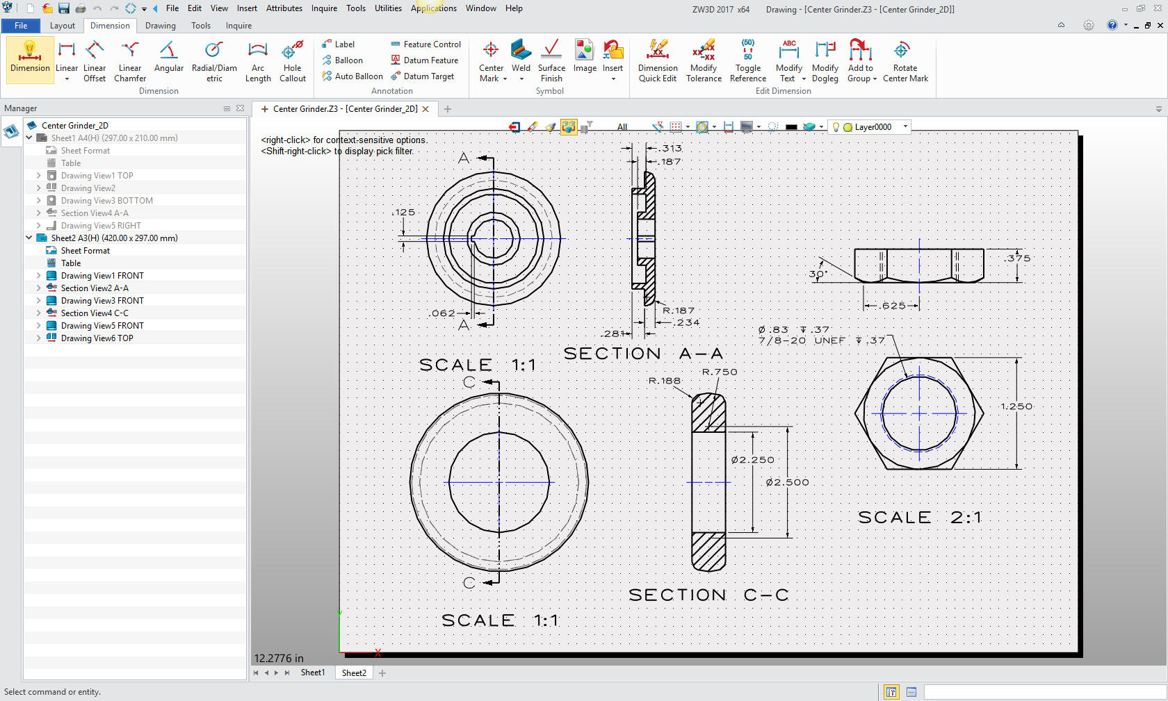
Here
are the views defined in the 2D sheet generated from the Center
Grinder assembly. We add the dimensions and we
are completely done with the part. Please remember, we have done
this all in one file. Think it through!
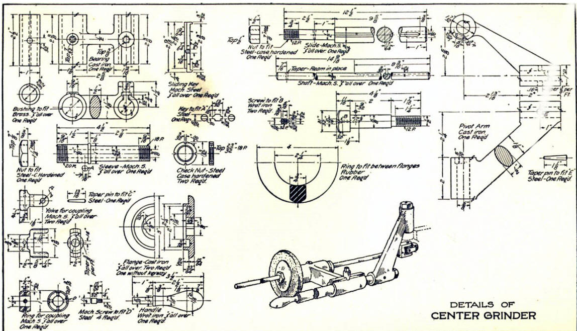
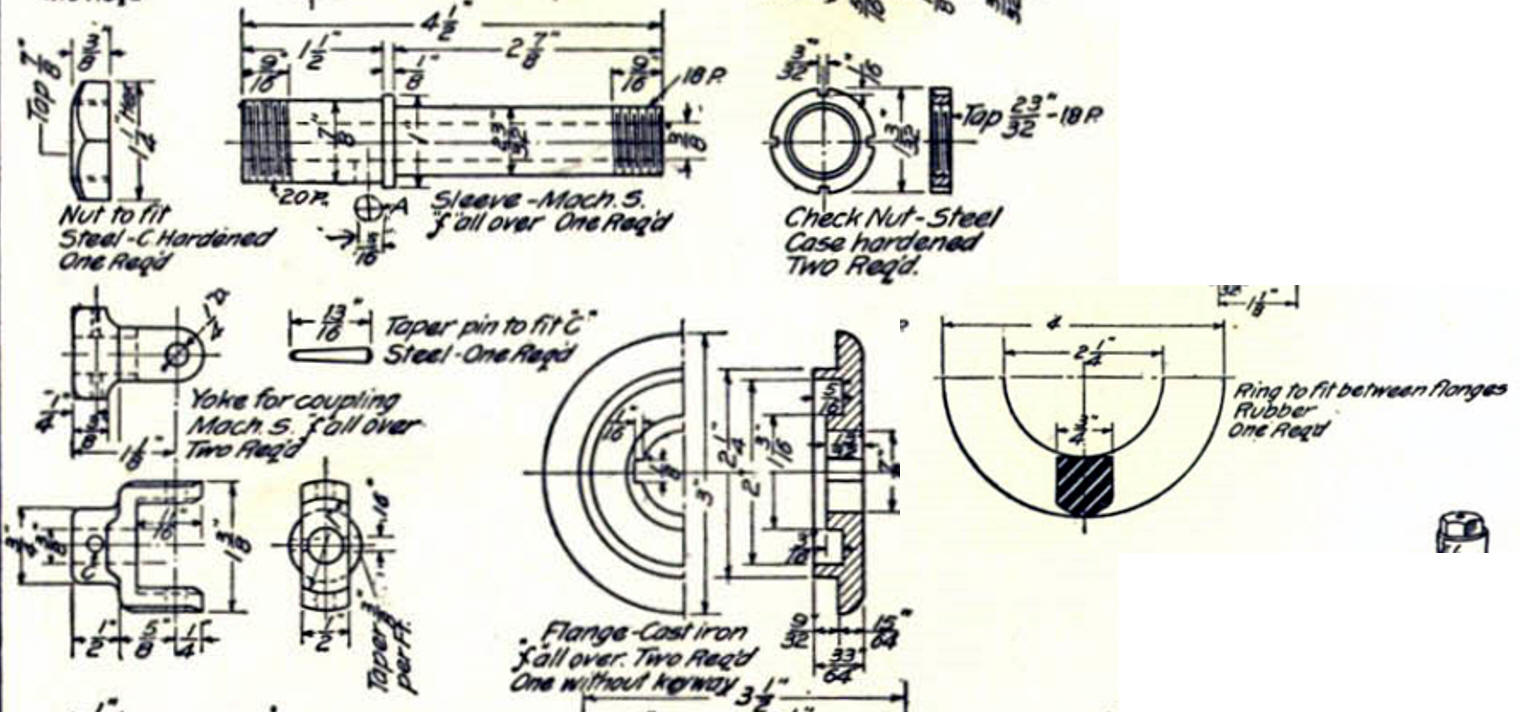
Here
is the original. I did add some dims that were not defined.
Now for lesson Four:
3D
Modeling Techniques ZW3D Lesson Four
If you would like
to try ZW3D, please download for a 30 day evaluation.
For more information or to download ZW3D
Give me a call if you have any
questions. I can set up a skype or go to meeting to show this part
or answer any of your questions on the operation of IronCAD. It
truly is the very best conceptual 3D CAD system.
TECH-NET Engineering Services!
We sell and
support IronCAD and ZW3D Products and
provide engineering
services throughout the USA and Canada!
Why TECH-NET Sells IronCAD and ZW3D
If you are interested in adding professional
hybrid modeling capabilities or looking for a new solution to
increase your productivity, take some time to download a fully
functional 30 day evaluation and play with these packages. Feel free
to give me a call if you have any questions or would like an on-line
presentation.
| |