Let me introduce you to Caleb Simpson
and Simpson Offroad.
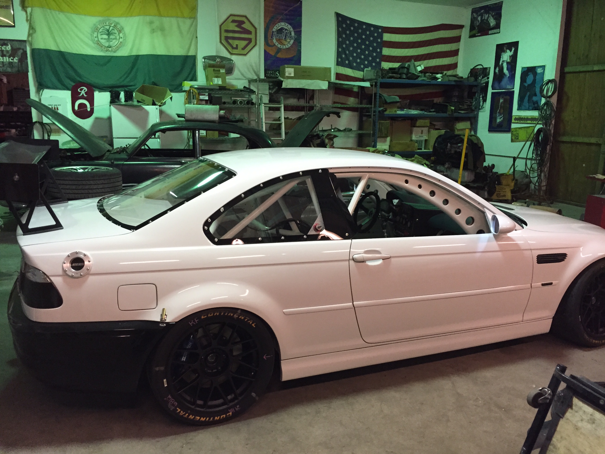
The idea for Simpson Offroad started out after some time working
at a race shop building road racing cars and some times building
them at my own shop. I have built everything from Spec class cars
that basically just get a roll cage, to full on balls to the wall
road racing cars. I have always been good working with my hands and
building things. So it wasn’t that unusual for me to get into
welding and fabricating.
At the same time, I was getting
into off-roading and realized that I was much more interested in
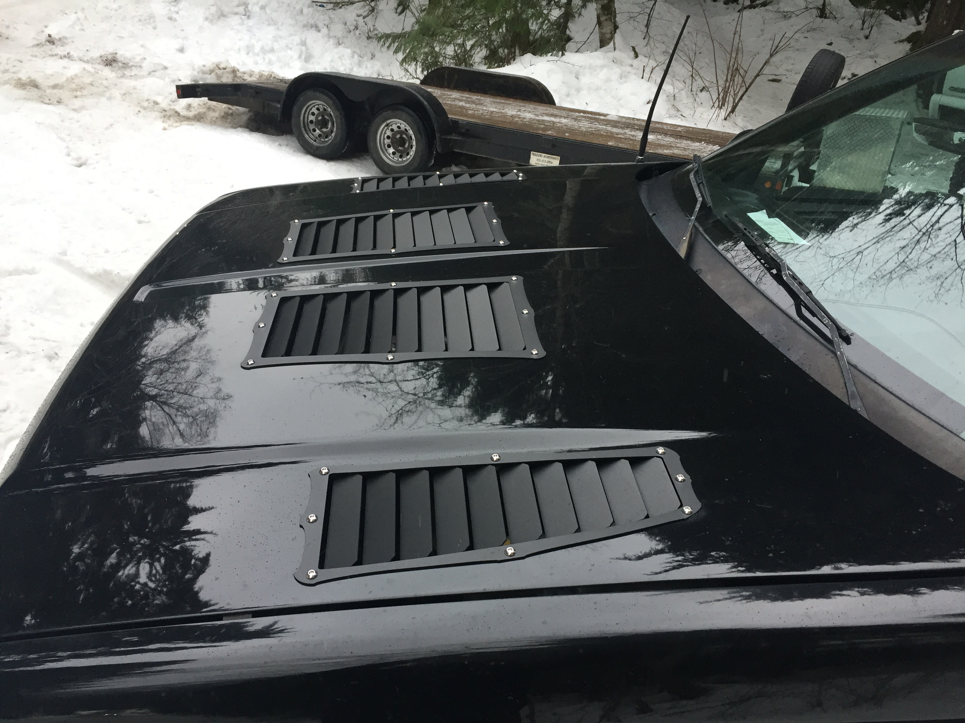
building trucks then race cars. Later on I started selling my first
product, offroad inspired hood vents/louvers. At the time I was
working a day job and doing this on the side. It started out really
good. Sales continued to increase each quarter for a couple years,
but with only one product, no means yet to introduce more products
and paying a third party to laser cut the vents, I decided to put it
on hold until I have more products designed, and the means of
producing all of them in house.
With the help of IronCAD,
I have starting that process. As I have been teaching my self the
ins and outs of IronCAD (with some help from online videos and a
couple calls to Joe), I have been working on a catalog of new
products. When I’m able to buy the equipment necessary, I will have
a good point to start.
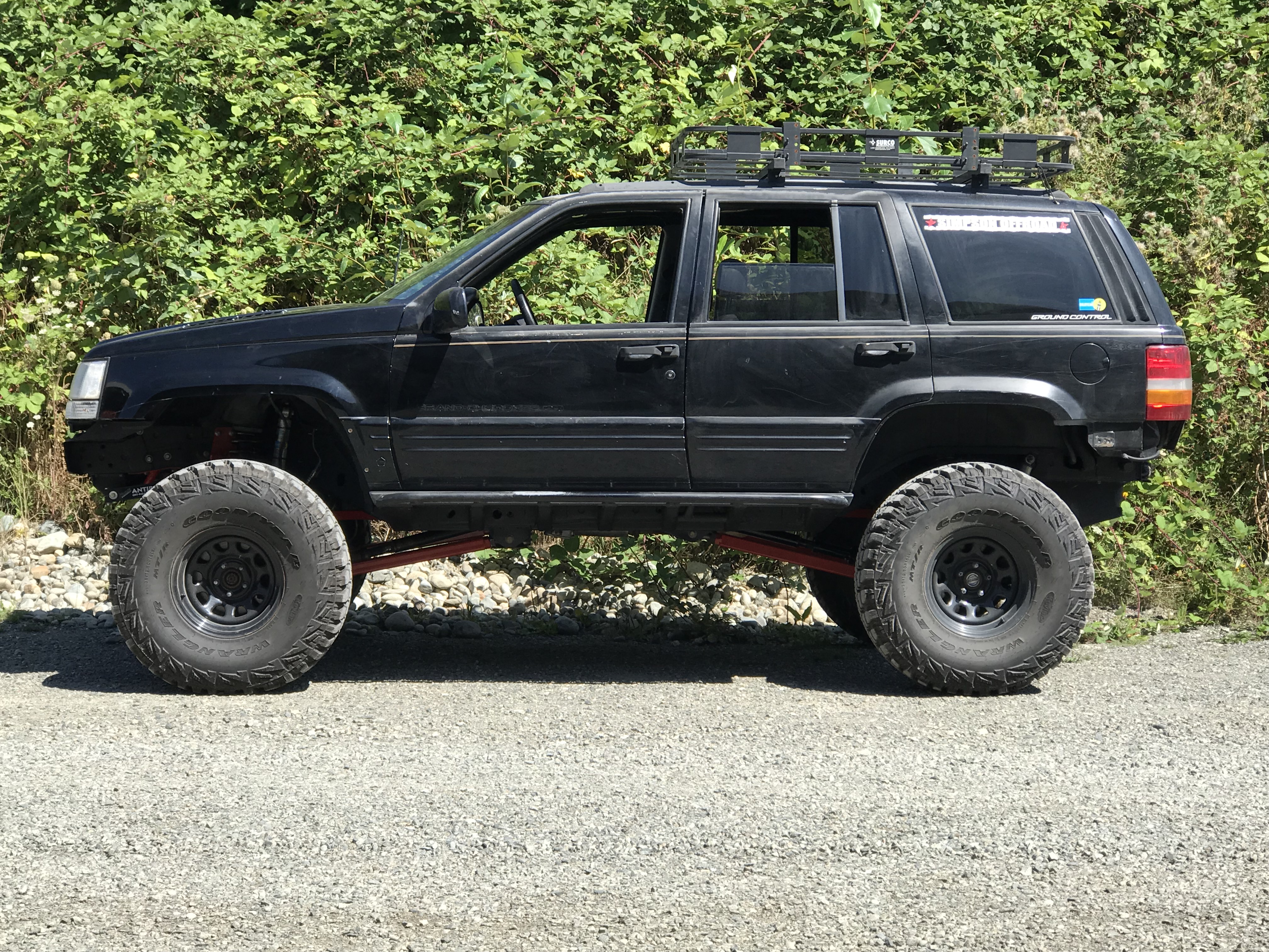
Some of the products I’ve been
working on are lift kits for Jeeps, cargo area toolbox/utility
drawers for storage, quick release seat mounts, and more. IronCAD
has also helped me design, test, and redesign some inventions that
I've been working on. One in particular may be my ticket to really
starting Simpson Offroad.”
If you would like to contact Caleb
about his services you can contact him at:
caleb@simpsonoffroad.com
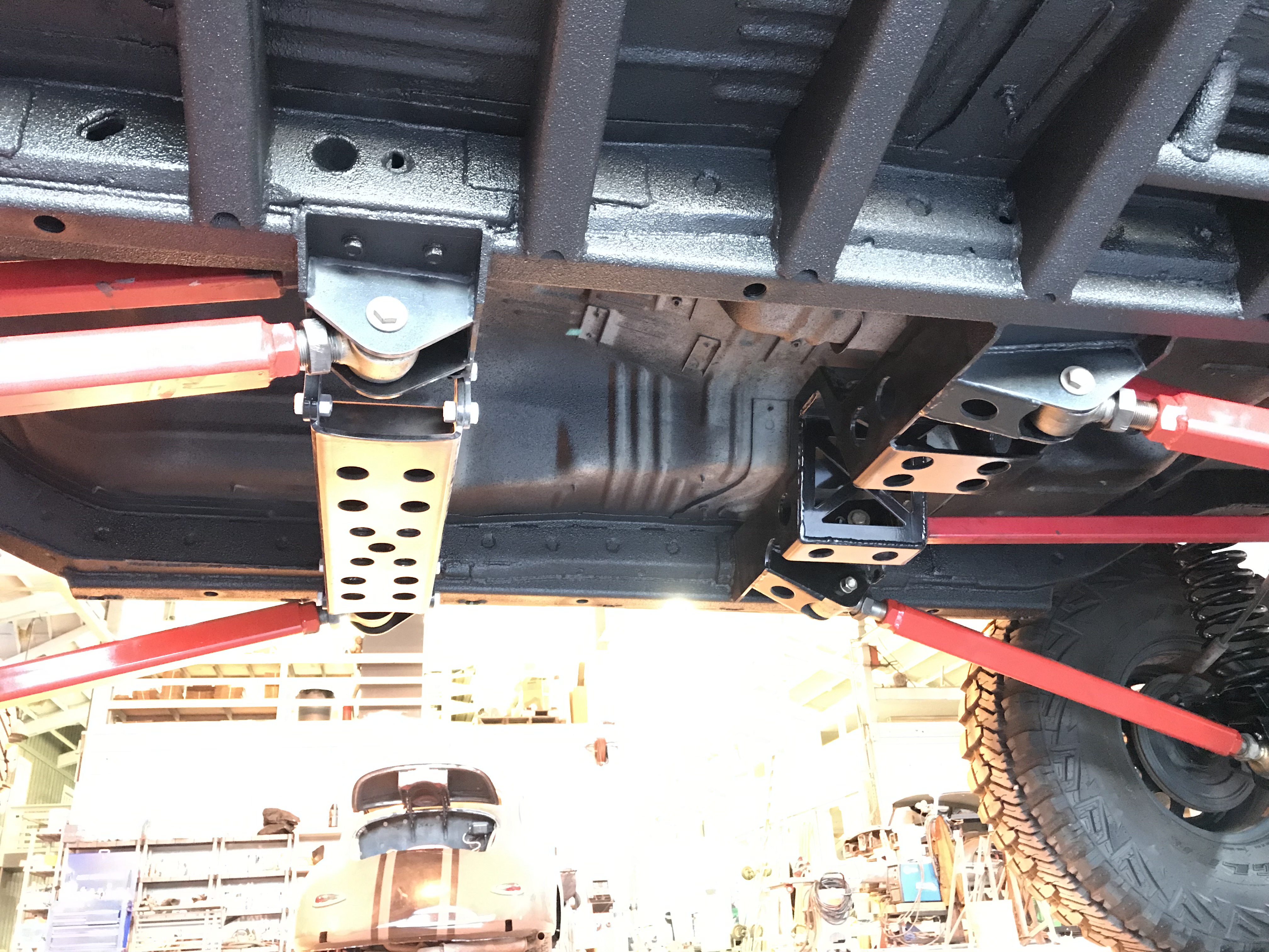
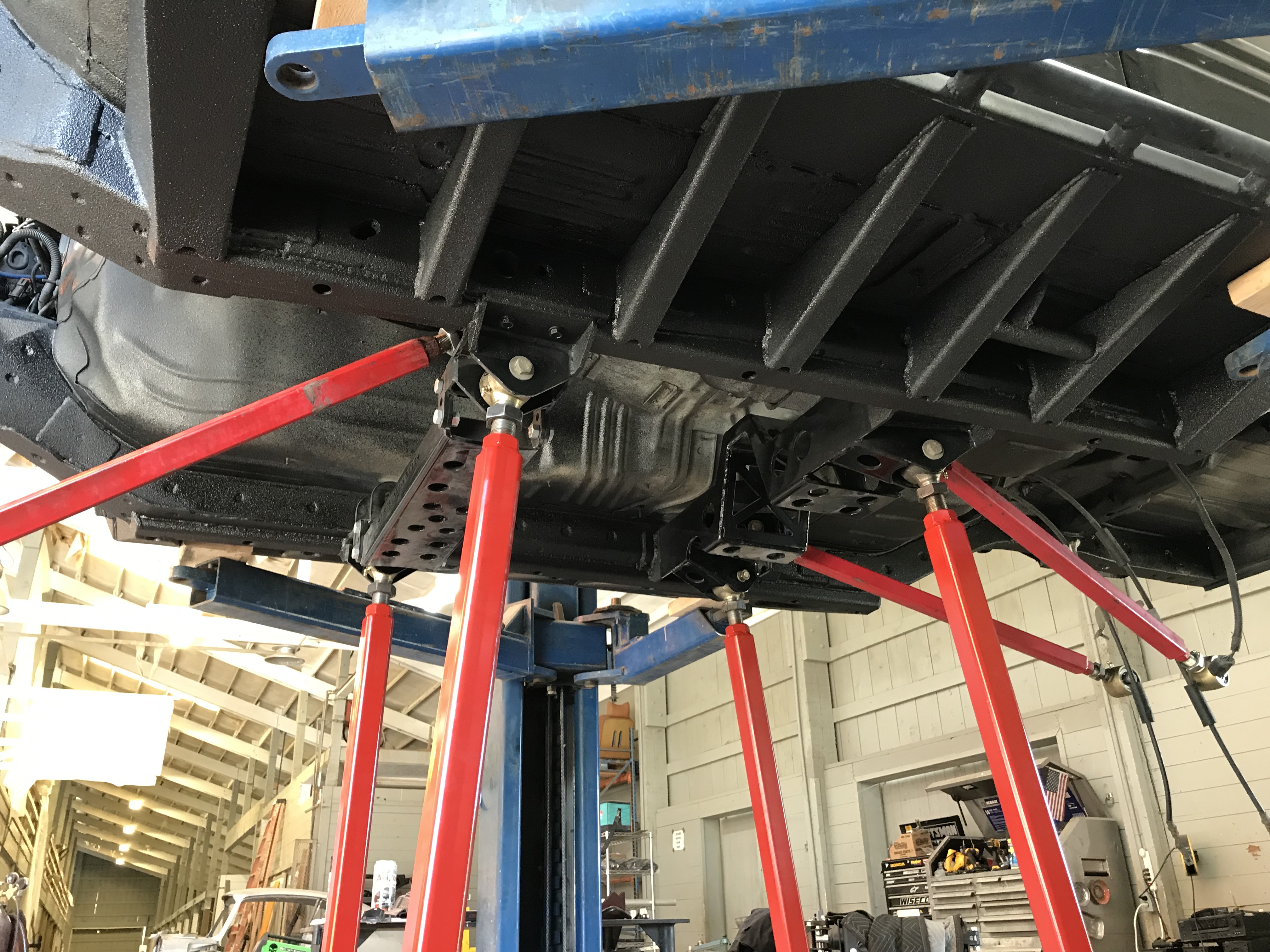
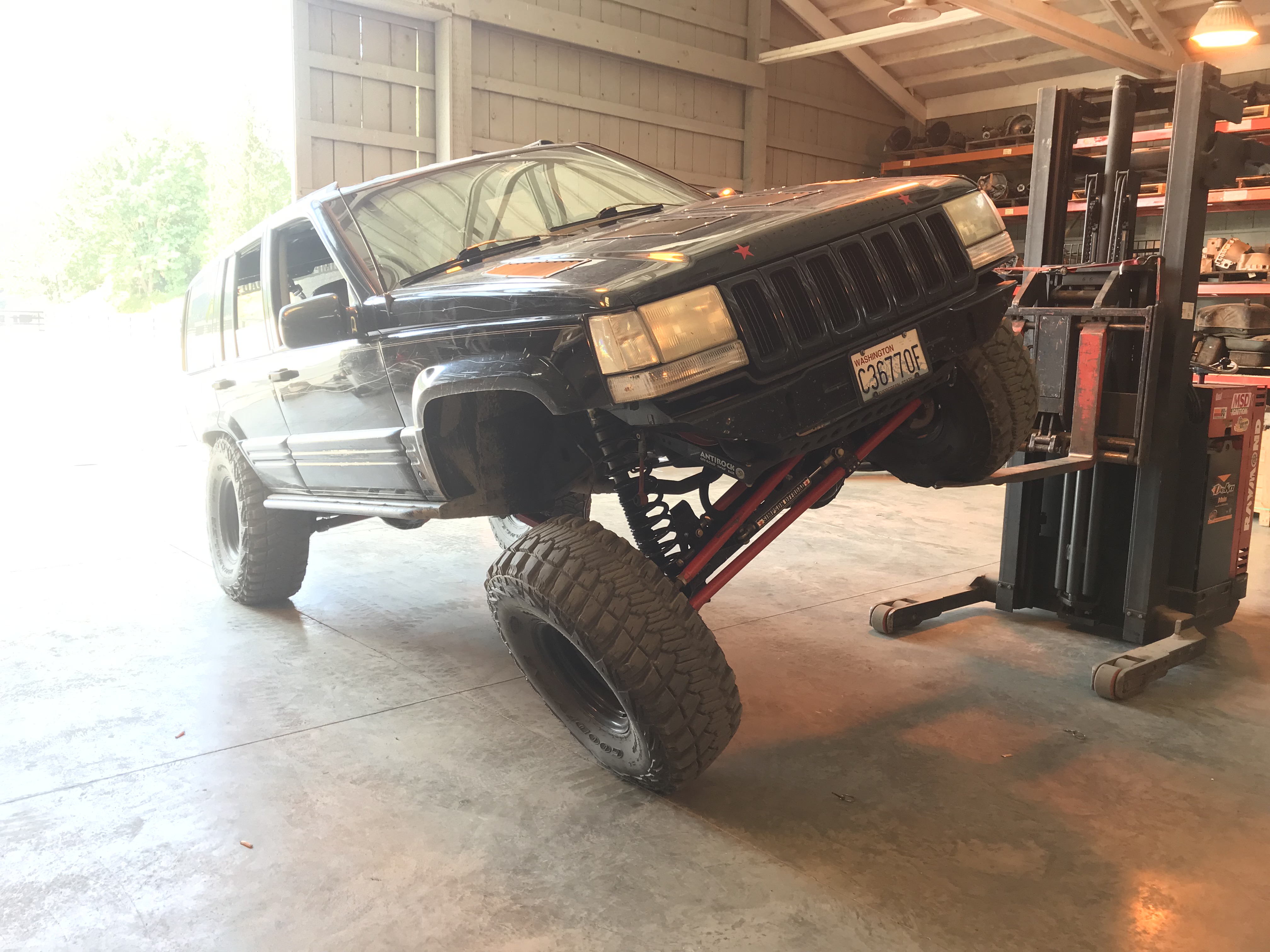
Here a few images of Caleb's work.
I asked Caleb if he had any engineering or
drafting training.
"Nope, I haven’t had any Engineering, etc.
education. I think I just have a gift of figuring things out.
Probably why I’m a pretty decent mechanic. I just know how things
work, more or less. I did go to Harley Davidson motorcycle school
after high school. I worked as a mechanic for about 6 years. But I
was already working on things before that."
I believe many are born draftsman and engineers!
Here is
some of Calebs work. I was amazed at his mastery of the sheet metal
module. He generated and used the flat patterns. How he figured this
all out without a support call is a credit to Caleb and to the ease
of use of IronCAD.
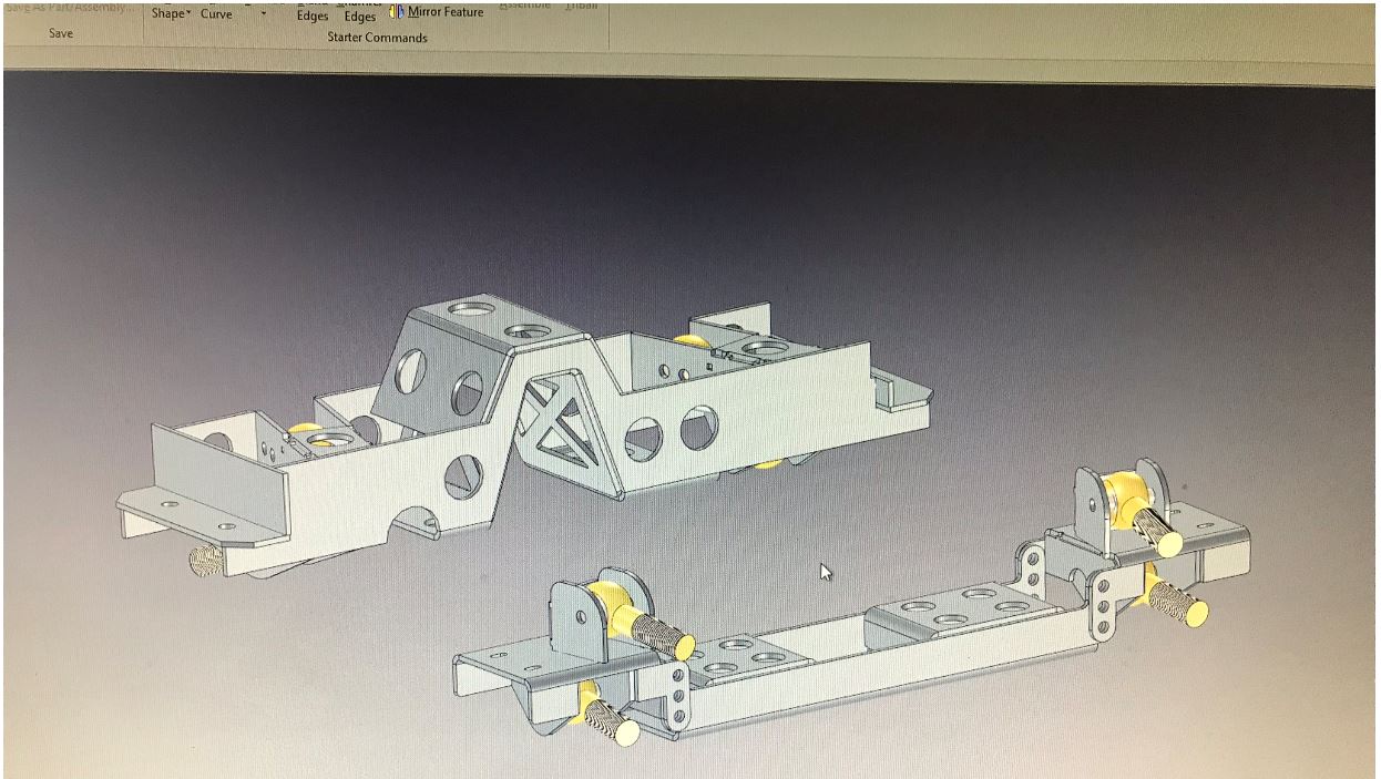 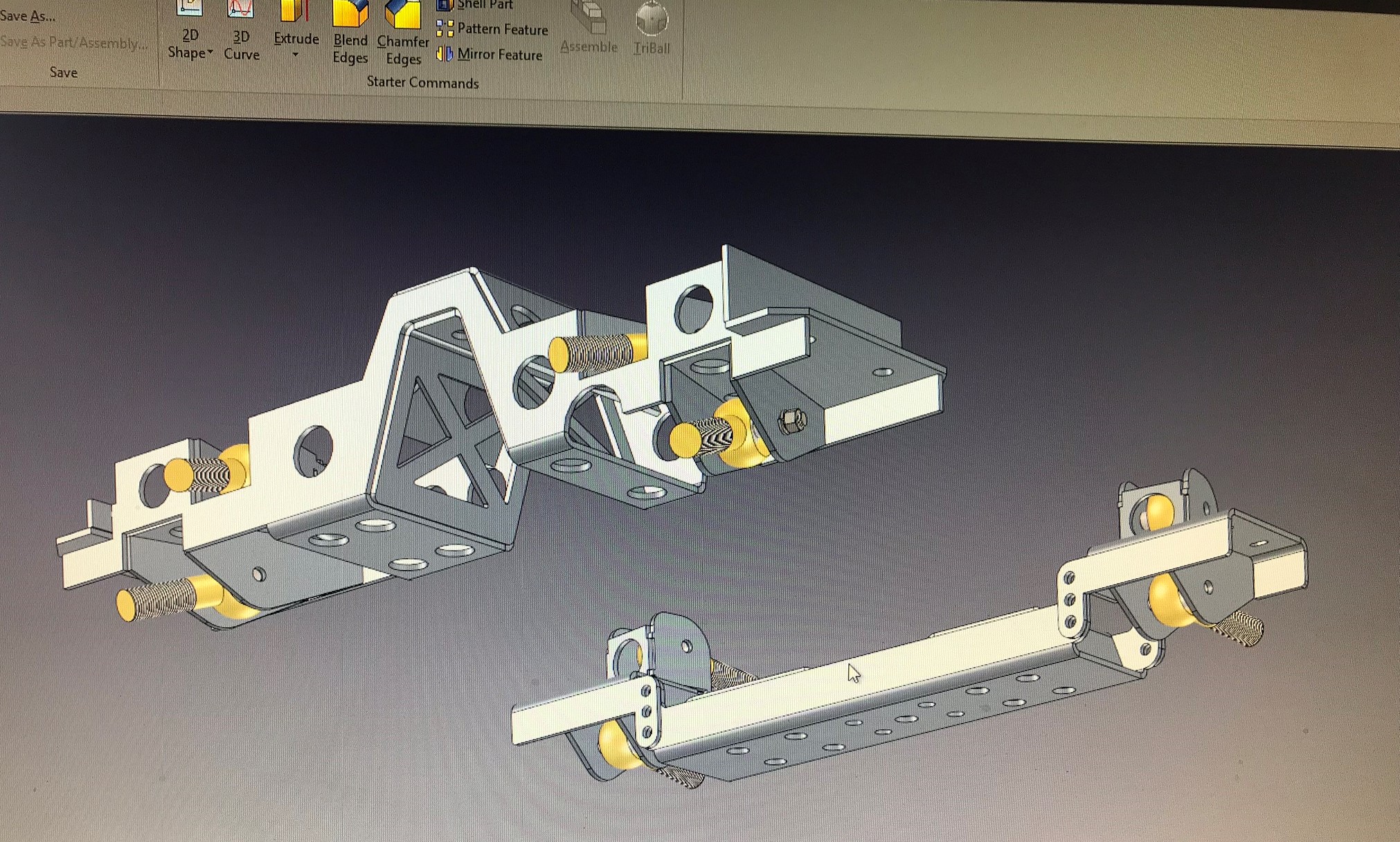
Deconstructing an Assembly
Caleb sent me an email requesting some help in constraining his
suspension assembly. I really didn't help, but he figured it out for
himself.
This was the second request for support since he
purchased IronCAD in November of 2018! This could show you how easy
IronCAD is to use, but it really shows Caleb skill in learning the
package.
Even though I offer
free support from 4am to 3pm by Skype Week days and 4am to 10am if I
am around on the weekends.
When he sent me this model I was
amazed how proficient he is. I asked if I could use it for an
example of my customers projects.
As I prepared the assembly
for a few interesting image I realize that there were some basic
IronCAD assembly processes overlooked. I again asked if I could
deconstruct the assembly and put it in a bit of more usable format.
Sounds good. That’s one thing that I haven’t been paying enough
attention too. I’m always willing to learn. Thanks.
Thanks for your time.
Caleb Simpson
425.802.8482
So let's get started.
As I
got into this, my goal was to organize the assembly. But as I
scrutinized it, I found a few modeling and design discrepancies. I
started doing a design check and realized this was going beyond the scope
of this article. The first thing I noticed was there was no linking
of parts. Linking is the way you defined the duplicate parts in an
assembly in SME to create the parts list.
I talked to Caleb and he saw no problem
with me doing a design check. So I will do that at a later date.
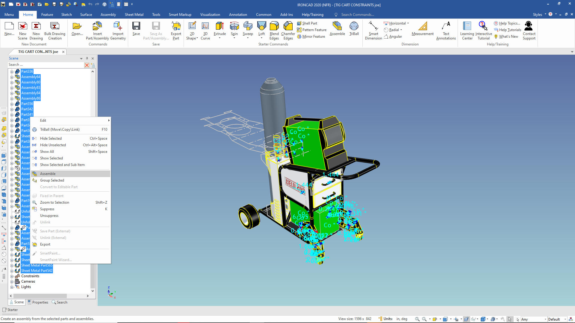
First thing is to put all of the features, parts and sub-assemblies in a top assembly. That is
done by highlighting all of the components and sub-assemblies and
select assemble.
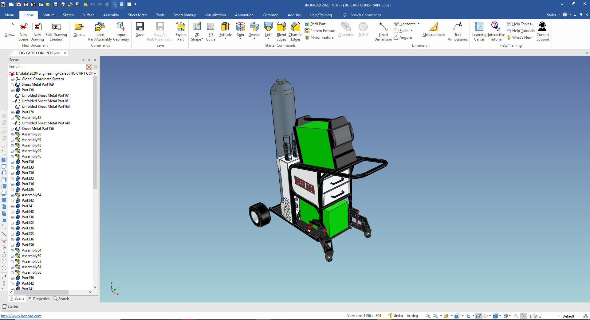
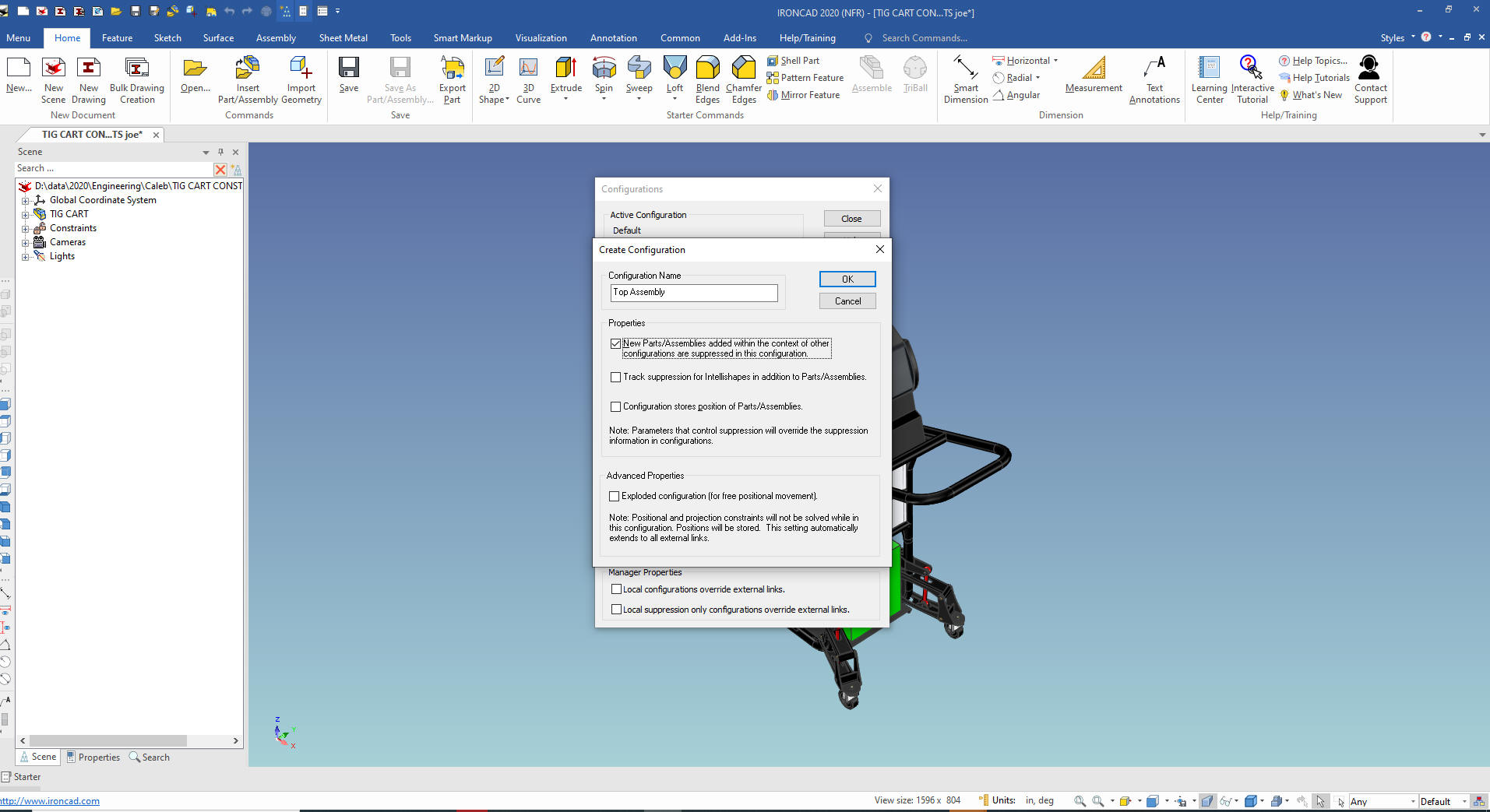
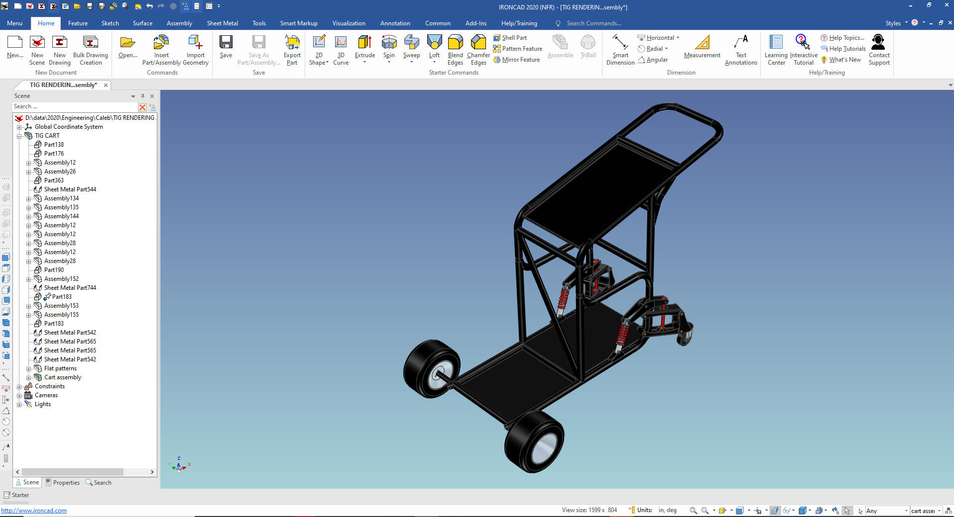
We
name the assembly "TIG CART", we also create a configuration call
"Top Assembly". When you work in a SME (Single Model Environment)
you have to separate the different components and sub-assemblies.
IronCAD take it from the components and sub-assemblies that are
active in the scene. Many other SME, which there are only around 4
at this time, use levels.
Now I
see a few flat patterns. So we put them into and assembly and name
them flat patterns. I know
these are not assemblies but this function also allows me to gather
non-functioning components together to clean up the clutter. We can
select them individually with the control button depressed!
They were already suppressed and the assembly now named
"Flat Patterns" is suppressed. We can set them as a configuration
later if we need an AID (Associated Information Document) to
generate a .dxf for manufacturing.
Note: Assembly is a bit of
a misnomer since many times this is just an unrelated group of
components or archived information. We do have a group command for
subsets outside the assemblies.
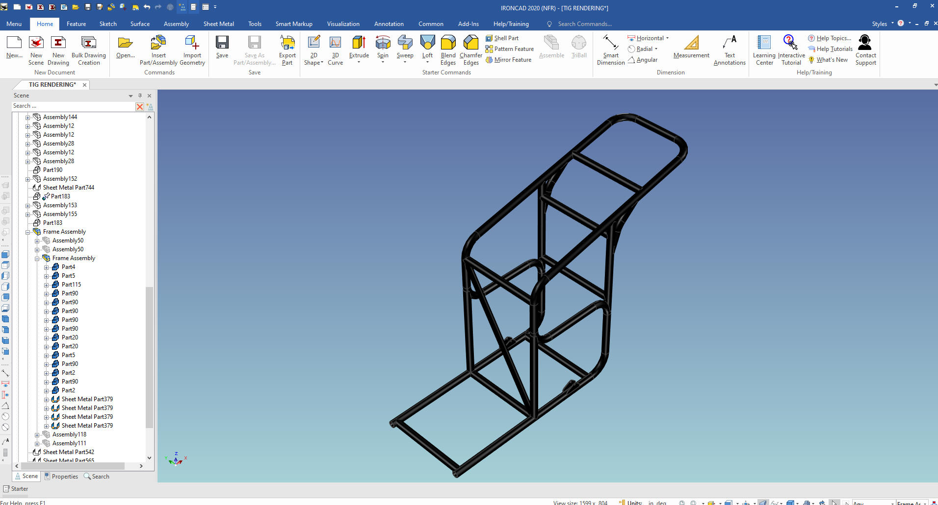
We now
start scrutinizing the different component, by hiding them. Let's
start with the obviously single components. We see that the frame is
an inseparable assembly. He has pinned it which means it is "Fixed in Parent", I
never use this feature so I remove it. We rename it to "Frame
Assembly" suppress the other components and sub-assemblies and
create a configuration of the same name.
I see that the
current assemblies are not giving me the information I need. I will
disassemble all of the assemblies in the Frame Assembly and start
over.
No lets take a closer look at our frame assembly.
We have to create the basic inseparable frame assembly. I have
made a configuration called "basic frame assembly". You should make
a configuration for every part or assembly that will require an AID.
We have a few sub assemblies which we will define, I will not
make configurations at this time. You only really need
configurations for AIDs or when you are need to work back and forth
with a couple of configurations.
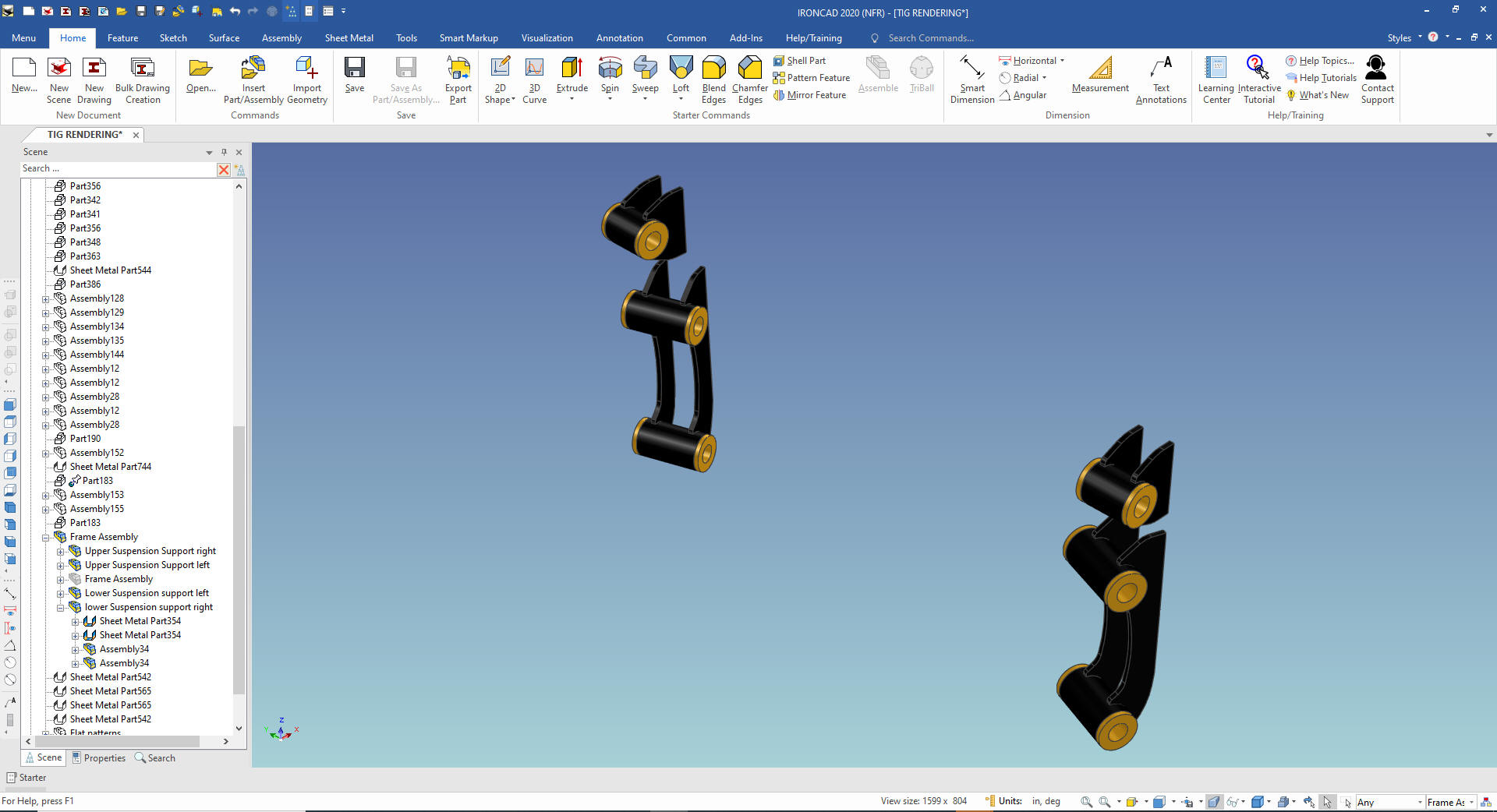
You can see the lower and
upper suspension supports. These should have been linked assemblies.
We will rename them accordingly.
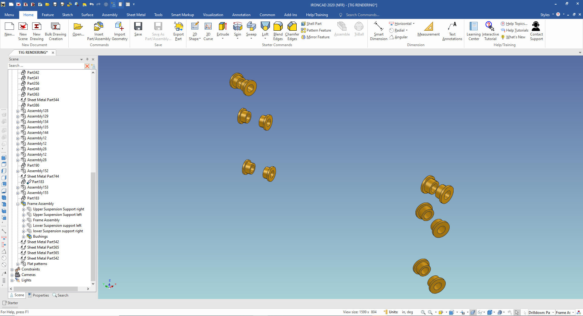
You
can see the bushings that are not part of these assembles so we will
have to create a new assembly named "bushings". We will put them
under the top assembly since they are not part of the Frame Assembly
We
are done with our Frame Assembly with the two sub-assemblies.
As I scrutinize the components I see that Caleb did not do any
linking. Linking is incredibly important since it is what defines
the quantity of the parts in the parts list.
I will not get
into each part of the frame
We would be doing more part
naming and configuration as we would create our documentation. But
we are just putting the assembly into defined assembly components
for now.
With my next article I will show to create the
documentation in IronCAD's documentation module.
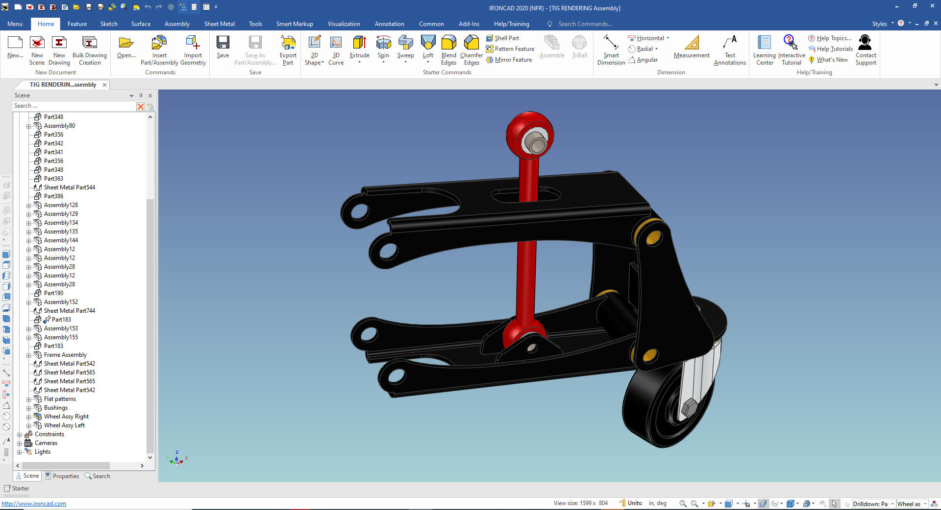
Now
for the suspension
We have a left and right suspension system
with some common parts and a few mirrored or "opposite" parts.
As we scrutinize the suspension we see a level of assembly. I
will call this the wheel assembly right. I will no go into mirror
linking these assemblies here. I will do that when I do the model
design check.
I create a Wheel Assembly Right configuration
and suppress all the unrelated part. I also do this on for the left
assembly also. But we only need one configuration to create the
documentation.
We
turn off our assemblies and take a look to see what else we need to
do. We drag the relevant parts to the correct assemblies, naming the
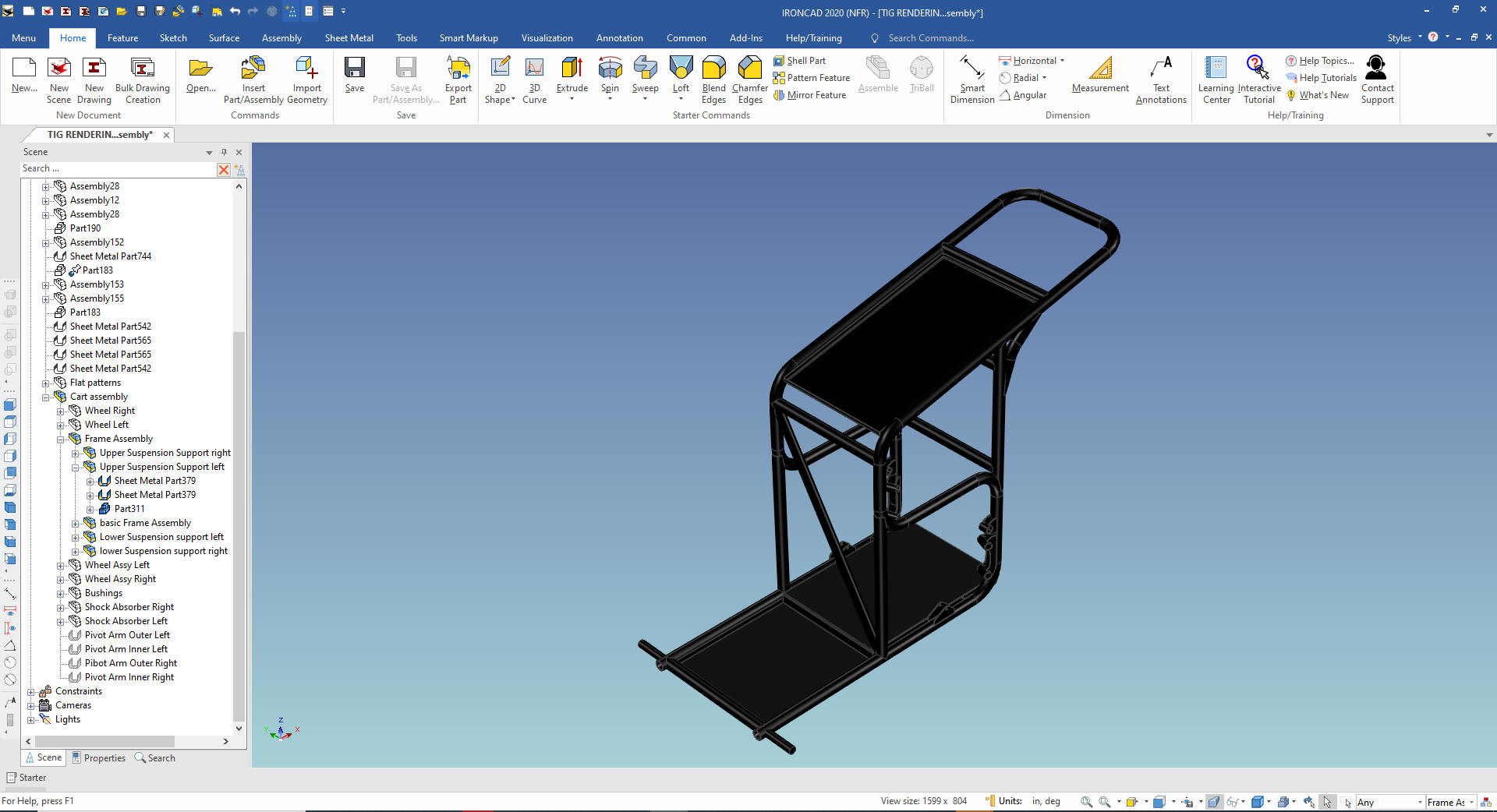
parts as we go. We now have the cart assembly defined.
Let's
add the Cover/Draw support assemblies, left and right.
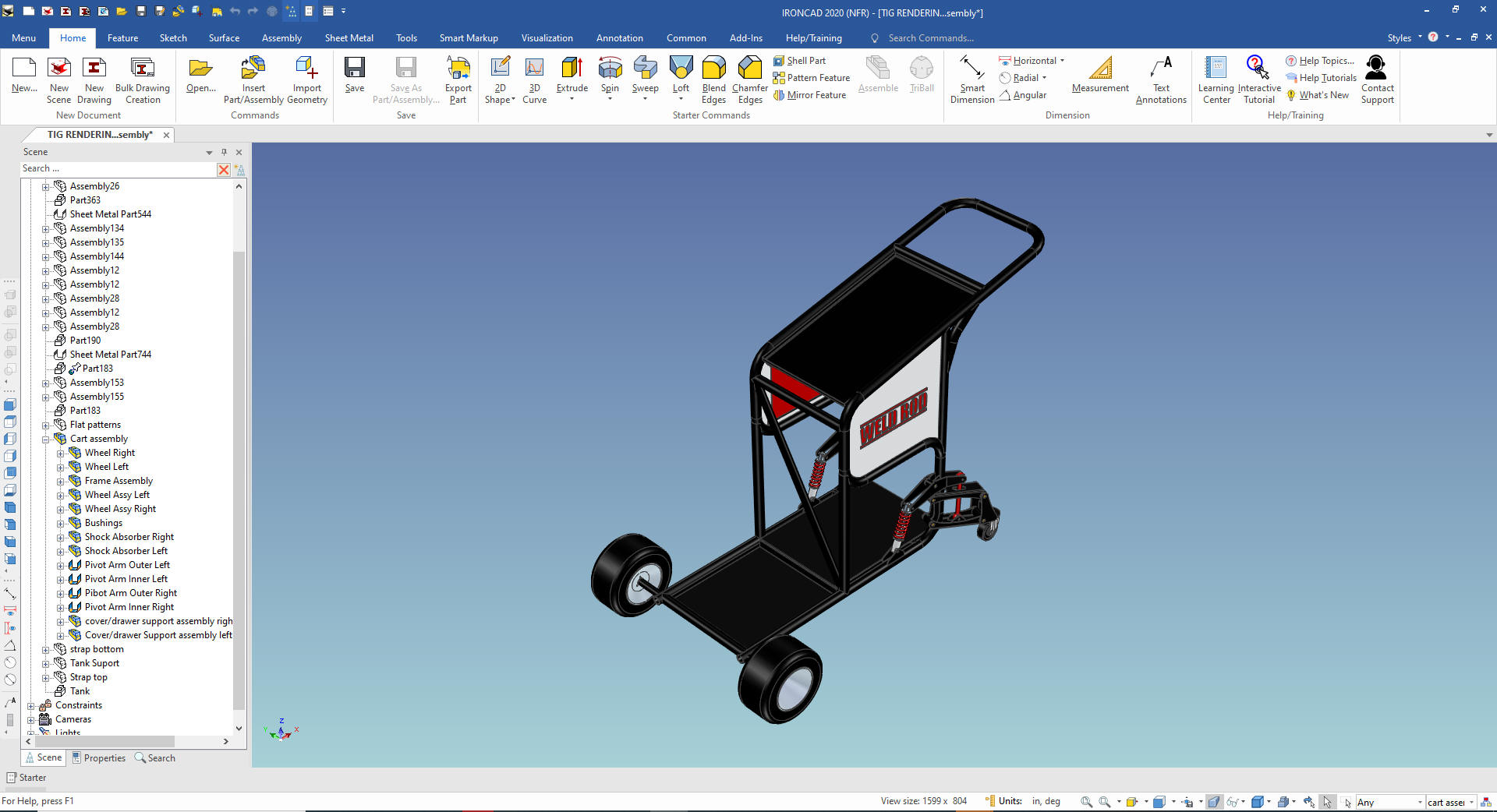
I
just keep organizing the parts into assemblies. It was now
relatively easy with most of the complicated assemblies out of the
way. I now have the
assembly to a level anyone with just a bit of IronCAD, Inovate or
Compose knowledge can manipulate the assembly.
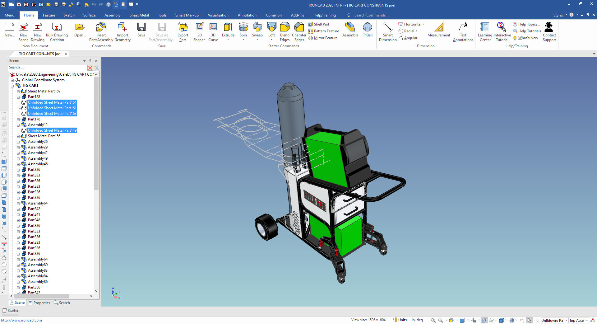
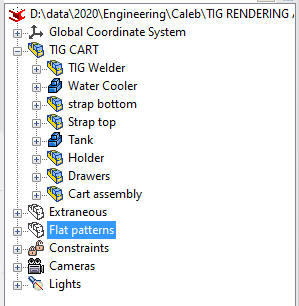
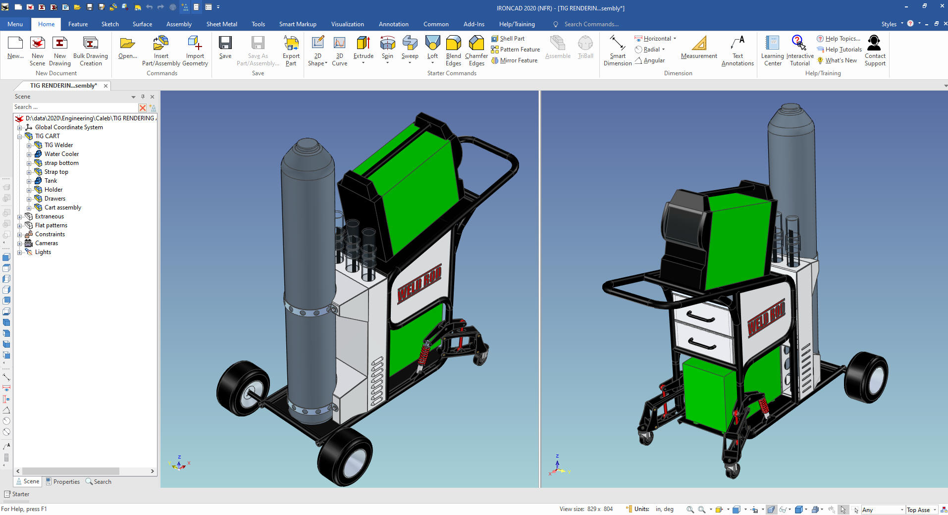
Here is the
scene browser.
And
the the assembly.
I found that many of the parts and assemblies were not linked
which is a must for a correct parts lists.
I also found some
discrepancies in the design and a few better way to design some of
the parts. I talked to Caleb and was willing to allow me to do a
design check. I will also create some AIDs (drawings).
I will
post them in a couple of weeks.
Thanks for Stopping by!
If you would like
to try IronCAD, please download for a 30 day evaluation.
If you would like more information or download IronCAD
To get more familiar with
IronCAD please got through the following course.
Self-Paced Training Guide - Introduction Course
TECH-NET
Basic IronCAD Training
Learning IronCAD in ONE Minute!
After you feel
comfortable with IronCAD, import a part or an assembly from your
current system and start modifying the parts and assembly.
Assemblies will come into one single model space with all the parts
available, usually named and organized into assemblies and
sub-assemblies. IronCAD will import parts and assemblies from all of
the popular packages.
Give me a call if you have any
questions. I can set up a skype or go to meeting to show this part
or answer any of your questions on the operation of IronCAD. It
truly is the very best conceptual 3D CAD system.
Please review these other exercises that
show the unique productive advantages of IronCAD, Streamline Sketching and
Feature Based Modeling over the constrained sketching of the
experienced Major CAD system user.
IronCAD vs Fusion 360
IronCAD vs Solidworks
IronCAD vs Creo
IromCAD vs NX
IronCAD vs CATIA
IronCAD vs Inventor
IronCAD vs Onshape
IronCAD vs Solid Edge
You
can see more on modeling techniques with ZW3D.
3D
Modeling Techniques Defined
TECH-NET Engineering Services!
We sell and
support IronCAD and ZW3D Products and
provide engineering
services throughout the USA and Canada!
Why TECH-NET Sells IronCAD and ZW3D
If you are interested in adding professional
hybrid modeling capabilities or looking for a new solution to
increase your productivity, take some time to download a fully
functional 30 day evaluation and play with these packages. Feel free
to give me a call if you have any questions or would like an on-line
presentation.
|
| |
|