The modeling technique is
hugely responsible for the level of productivity. Those of you that
are only trained in the constrained sketching world of the major CAD
systems
are truly limited by not using the freedom of Streamlined Sketching
and Feature Based Design,
that is available in even the most Pro/e-ish of CAD systems. If you
or your
designers are designing in these very unproductive and time
consuming processes it might be time to review your standard design
processes. Don't have any do you?
These
lessons started out as
product comparisons, but quickly turned into a study in 3D modeling
techniques.
Ironcad USA Webinars
When I introduce IronCAD's very
flexible design paradigm I have a hard time to get the Pro/e clone
users, like Solidworks and other programs to understand the drag and
drop design paradigm.
Download
IronCAD/Inovate and take
the one day and 17 lesson course. I get rave reviews from my new
customers. Give it a try, this is a fully functional 30 day
evaluation with all of the native translators so you have access to
your legacy engineering information.
IronCAD Self-Pace Training Course
I saw the
following Solid Edge YouTube tutorial and thought I would give it a
try on IronCAD. I have to tell you it is almost tortuous to watch
the Solid Edge presenter. I
have tried to do top down design in Solidworks and failed. Inventor
is a bit better but all of these programs including Solid Edge create
external parts. You will see a huge difference in IronCAD's true
single model environment.
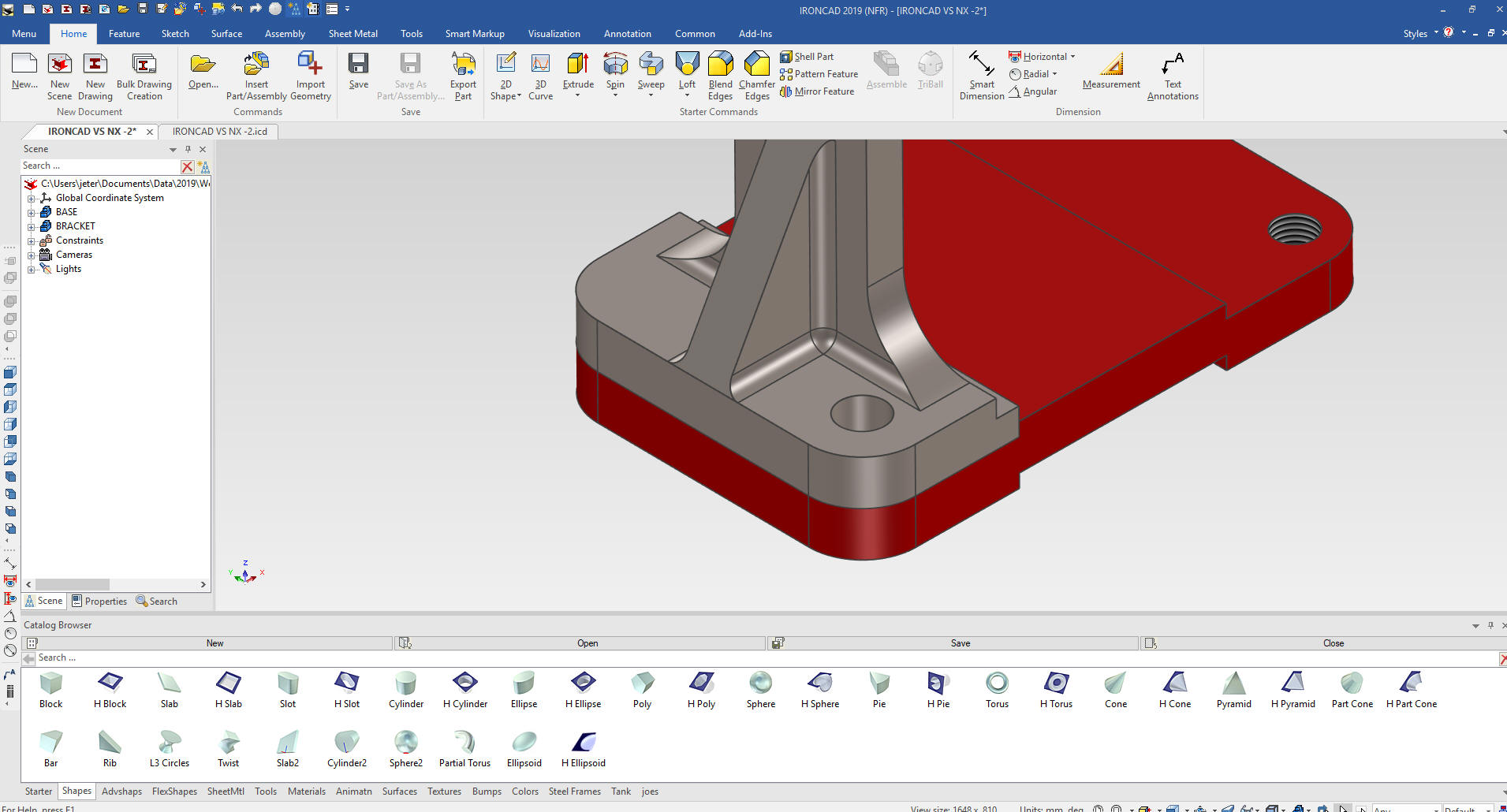
You can see the same basic part
done on NX. The part is dimensioned incorrect in the Solid Edge
drawing.
IRONCAD vs NX
Solid Edge is a constrained sketched based
system as are Fusion 360, Solidworks and Creo. In the following
lessons you can see that this modeling paradigm is use throughout
the industry causing millions of wasted hours.
3D Modeling Techniques Defined
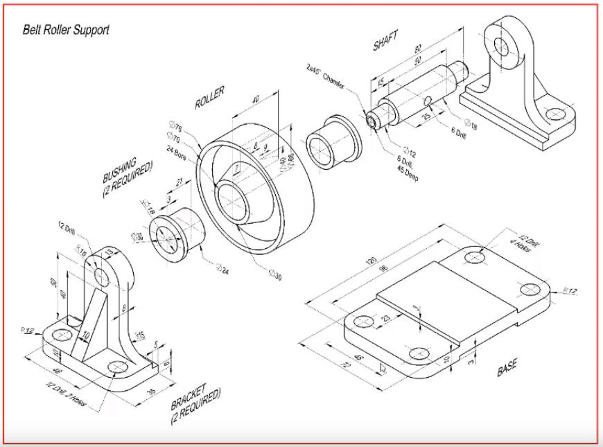
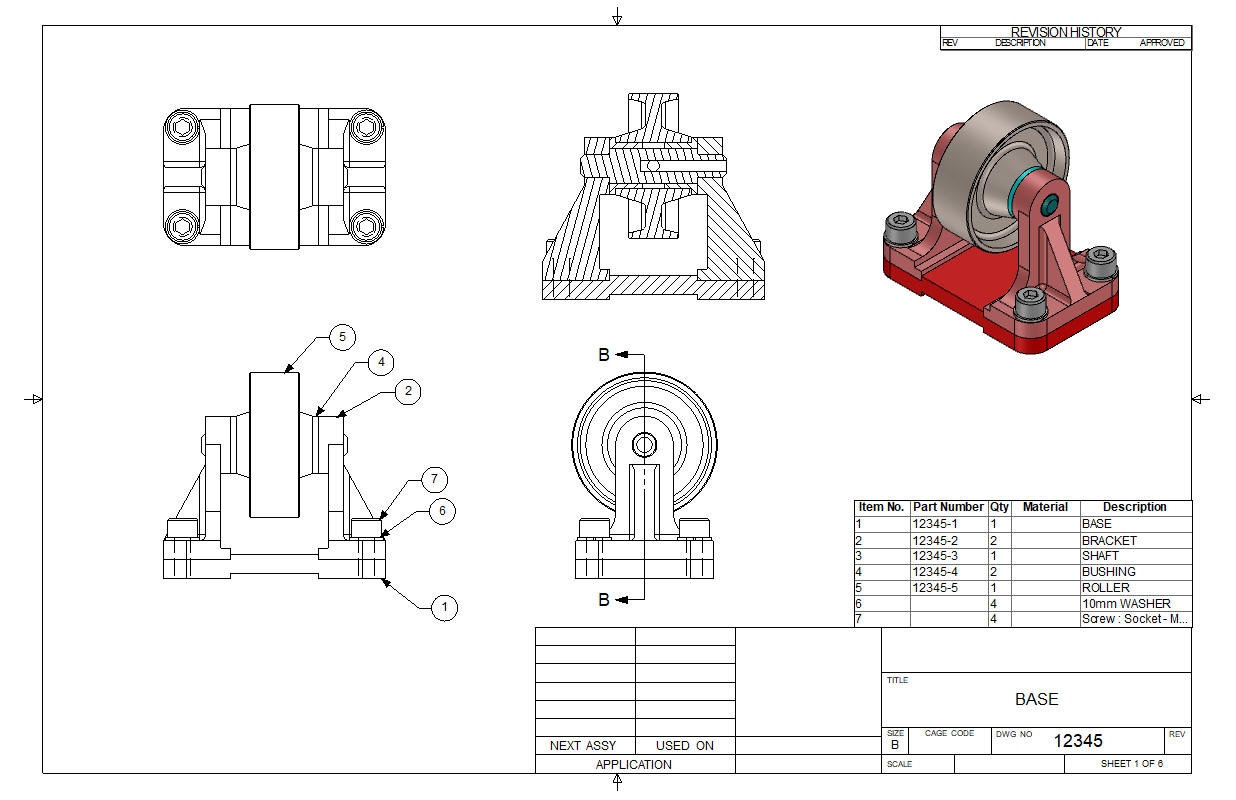
Here is the Isometric drawing. It is incorrect. So use the drawings
at the end for a good assembly. The top boss on the base should be
46mm.
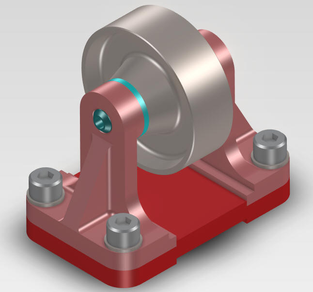
Assembly is the very
best feature of IronCAD. With its true single model environment it
offers the highest level of productivity. Watch how we use drag
and drop with a minimum of sketching to complete this job in no
time. There is no better program that can manipulate parts and an
assemblies in a 3D space.
While creating 3D models from a drawing is the very best
way to learn 3D CAD and maybe some design techniques is does not
expose the designer to the design flexibility necessary in product
design. IronCAD is all top down due to the single model environment.
Creating mating parts is a cruise. But modeling is just one aspect of a
well designed productive 3D CAD system.
IronCAD vs Solid Edge
I would do a
video, but I really am not good at it. So I will show you step by
step. I will try and get IronCAD support to create one. They are
very good.
I always create the part before I watch
the Solid Edge Video, so as to not taint my process. Of course,
there are a multitude of ways to create a model. There is no right
way, just more productive ways. But from what I have seen from these
very complicated processes done by the Solid Edge presenter, it is not
just limited by the 3D CAD system.
I have to say this is
incredibly simple. But the Solid Edge presenter has been
indoctrinated into these designs techniques. It started with Pro/e (Creo)
and has been the way the sketch, constrain and assemble. The
Solidworks clones are costing the industry millions, if not billions,
in lost productivity.
Here is IronCAD. We will set the units
to millimeters.
Learning IronCAD! Lesson 1
Setting up the Scene (Workspace)
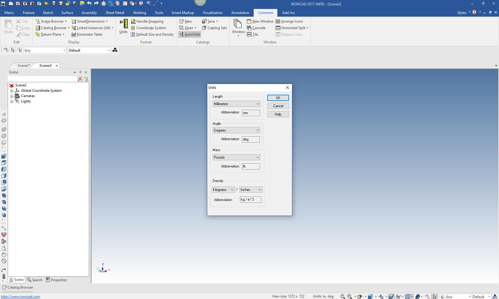
With IronCAD's single model environment
we do not have to prepare for it being an assembly. We just start
creating our part.
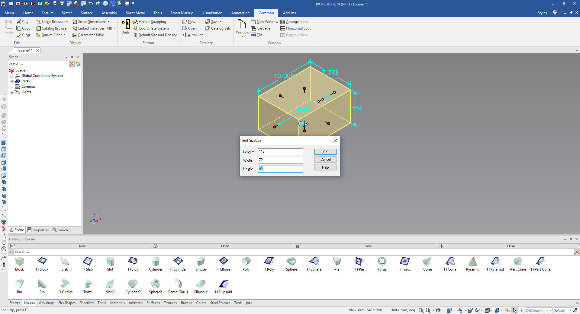
We will start by dragging and dropping a
block from the catalog and sizing it.
Learning IronCAD! Lesson Two
Drag and Drop Design
Designing with
Shapes
What are these shapes? We call them
Intellishapes. All are based on sketches that can be edited.
Learning IronCAD! Lesson 4
IronCAD Intellishape Deconstructed
What are
we Dragging and Dropping?
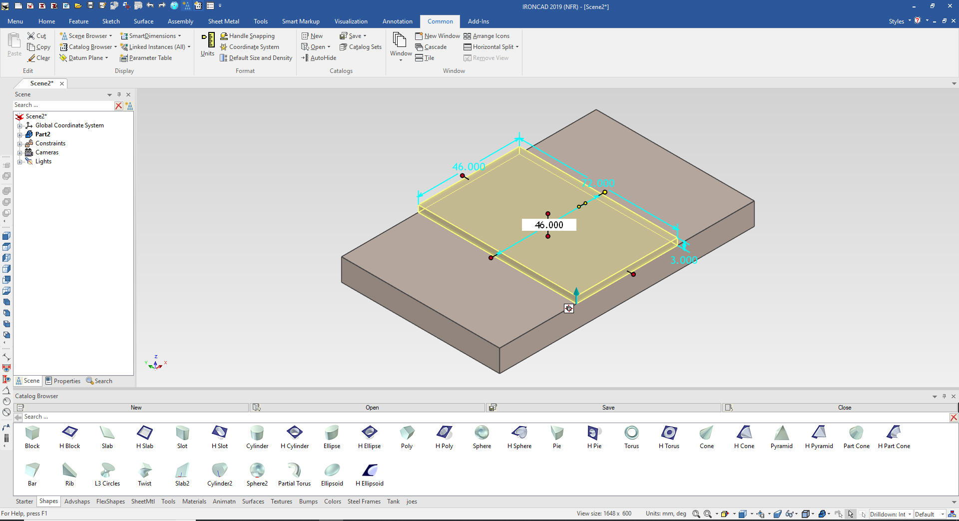
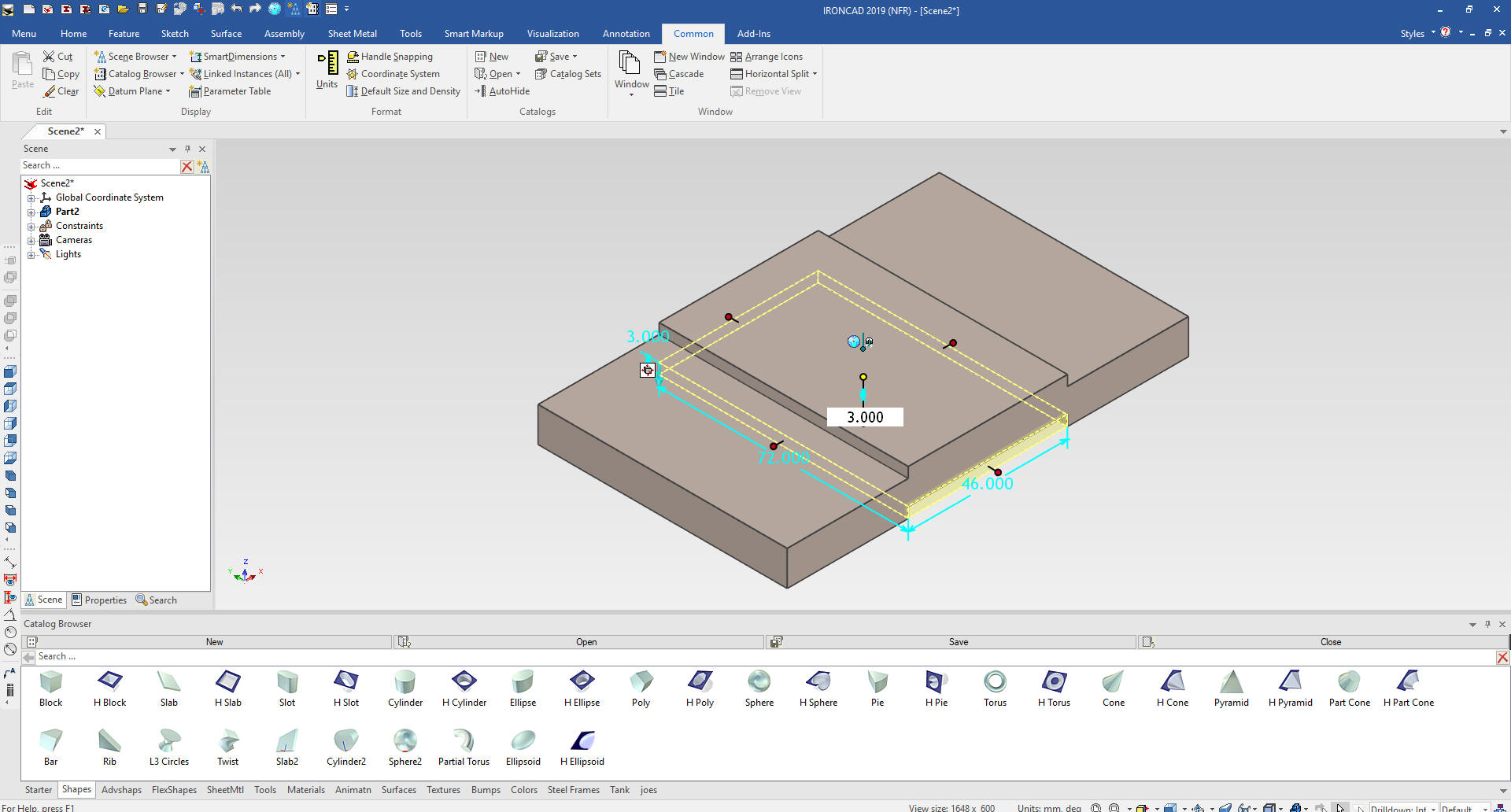
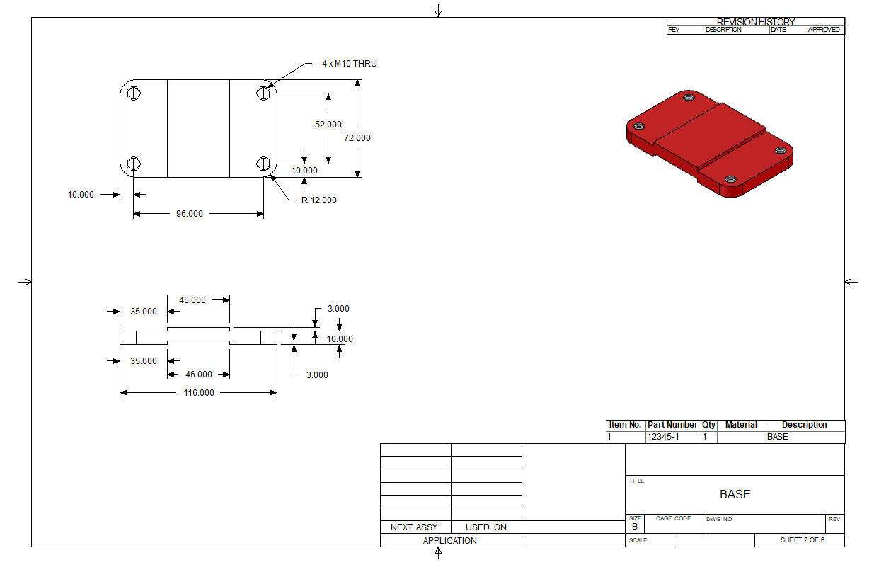
We then drag and drop another block and
locate it at mid-point of the top of the rectangle and size it by
pulling the side handle, holding down the shift key and matching the
edges, we set the height to 3 and then the length to 46. You can drop the feature on a variety of
snap points on the
part such as corners, edges, mid-points and centers.
Learning IronCAD! Lesson Two
Drag and Drop Design
Designing with
Shapes
We drag and drop a hole block at the
mid-point of the top face.
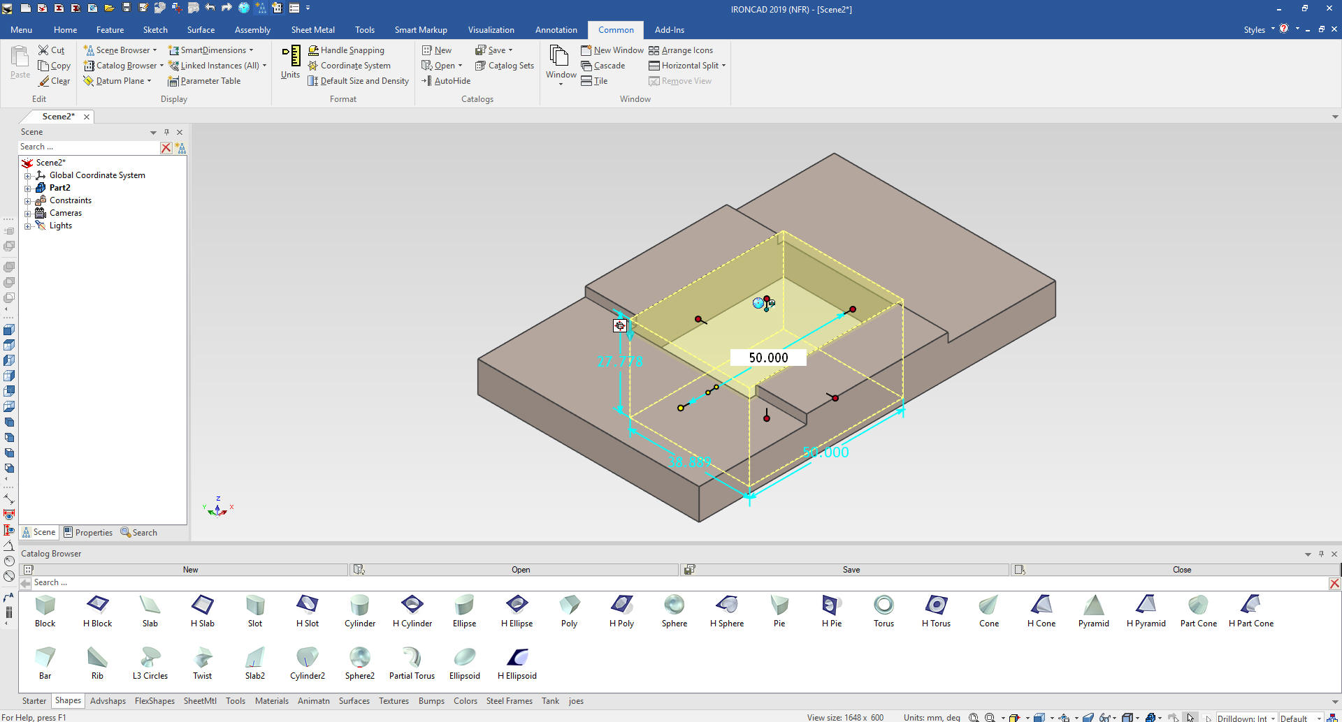
We grab the handles, hold down the shift
key and match the related faces and set the height to 3.
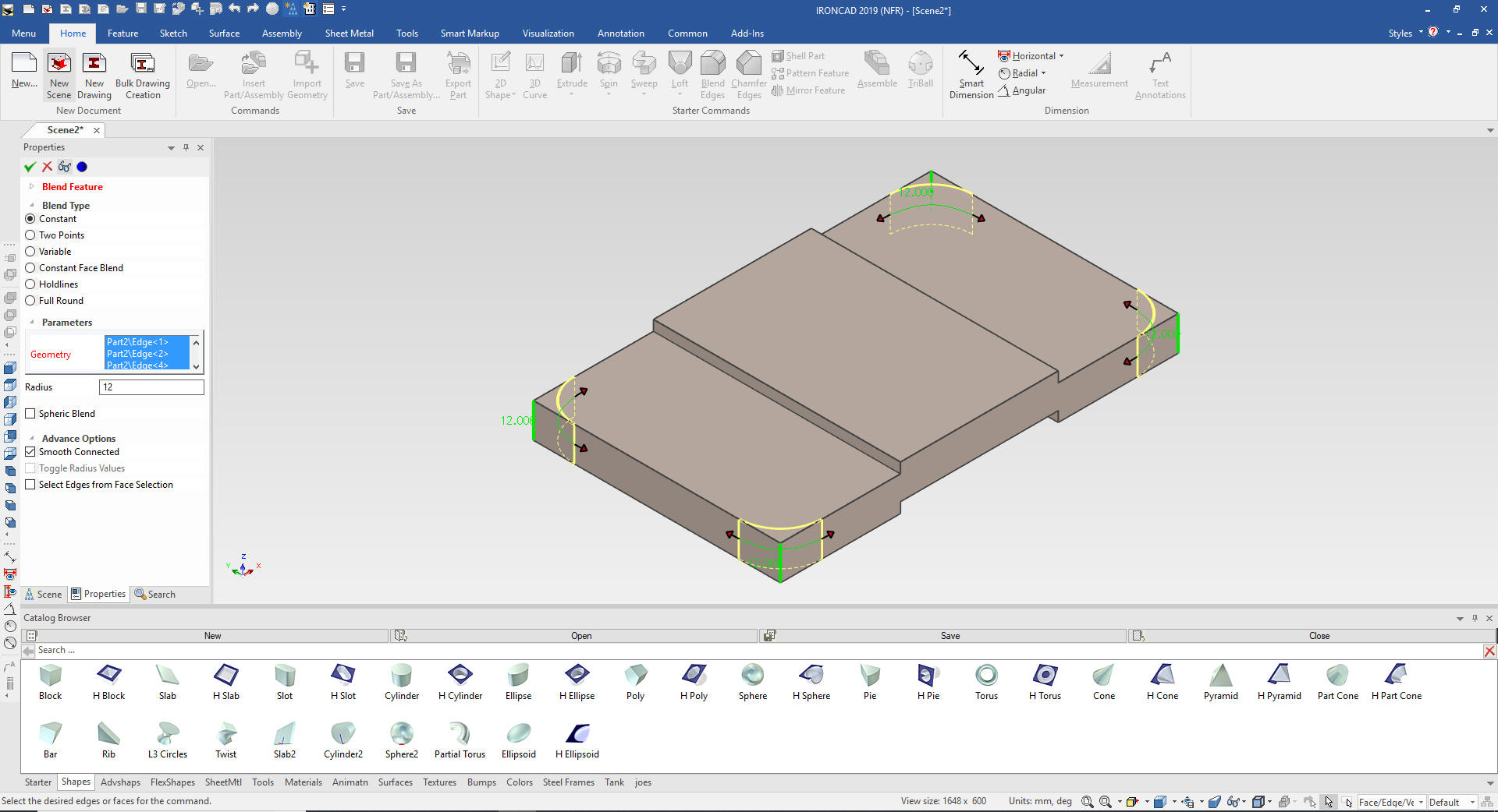
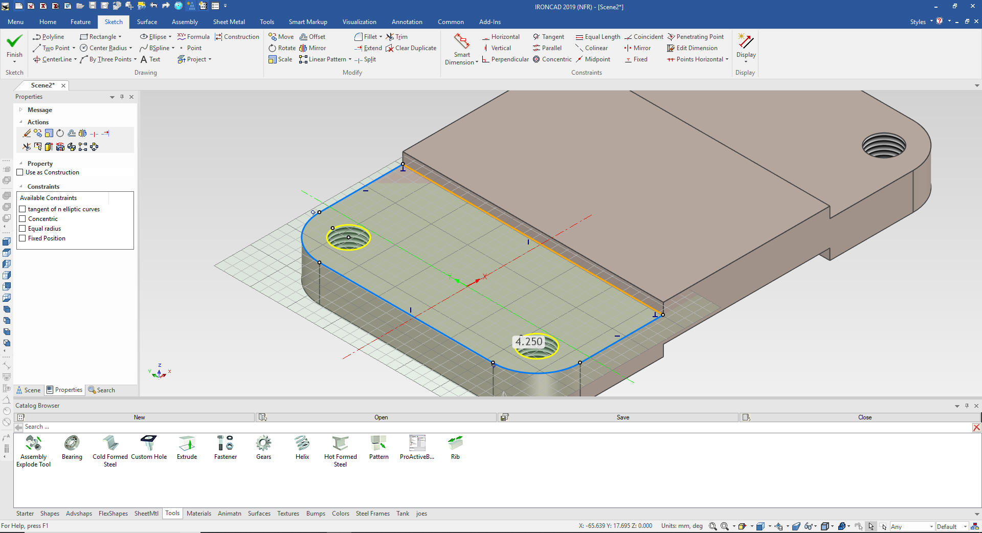
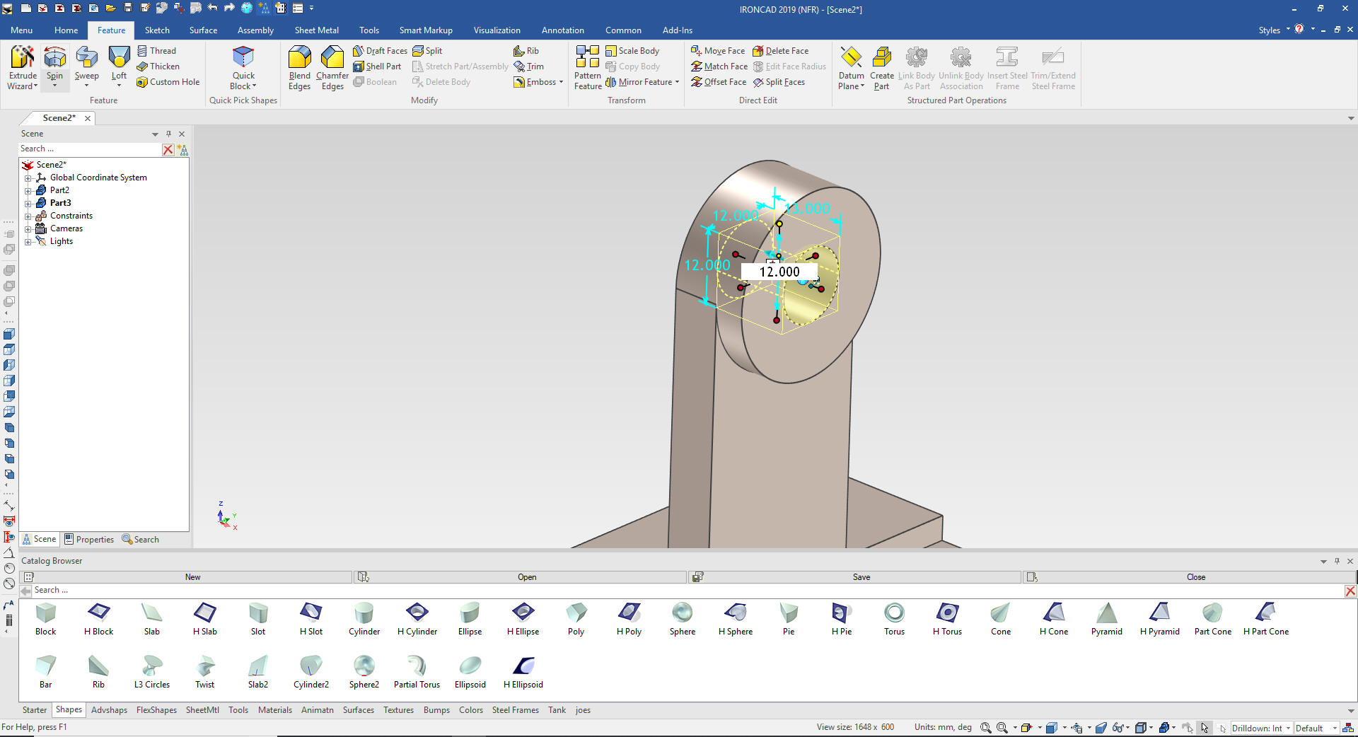
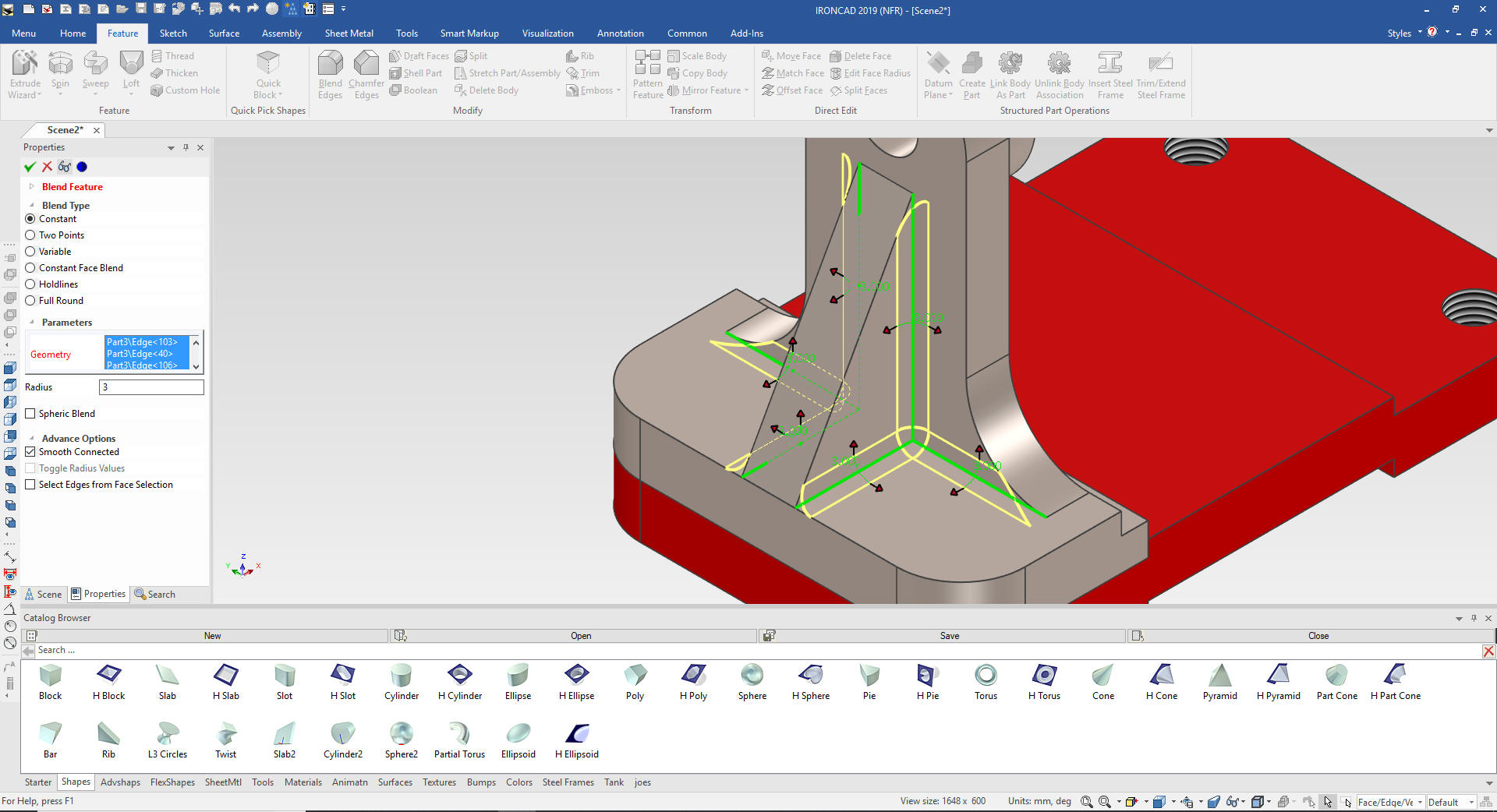
We put in the
4 12mm blends or fillets
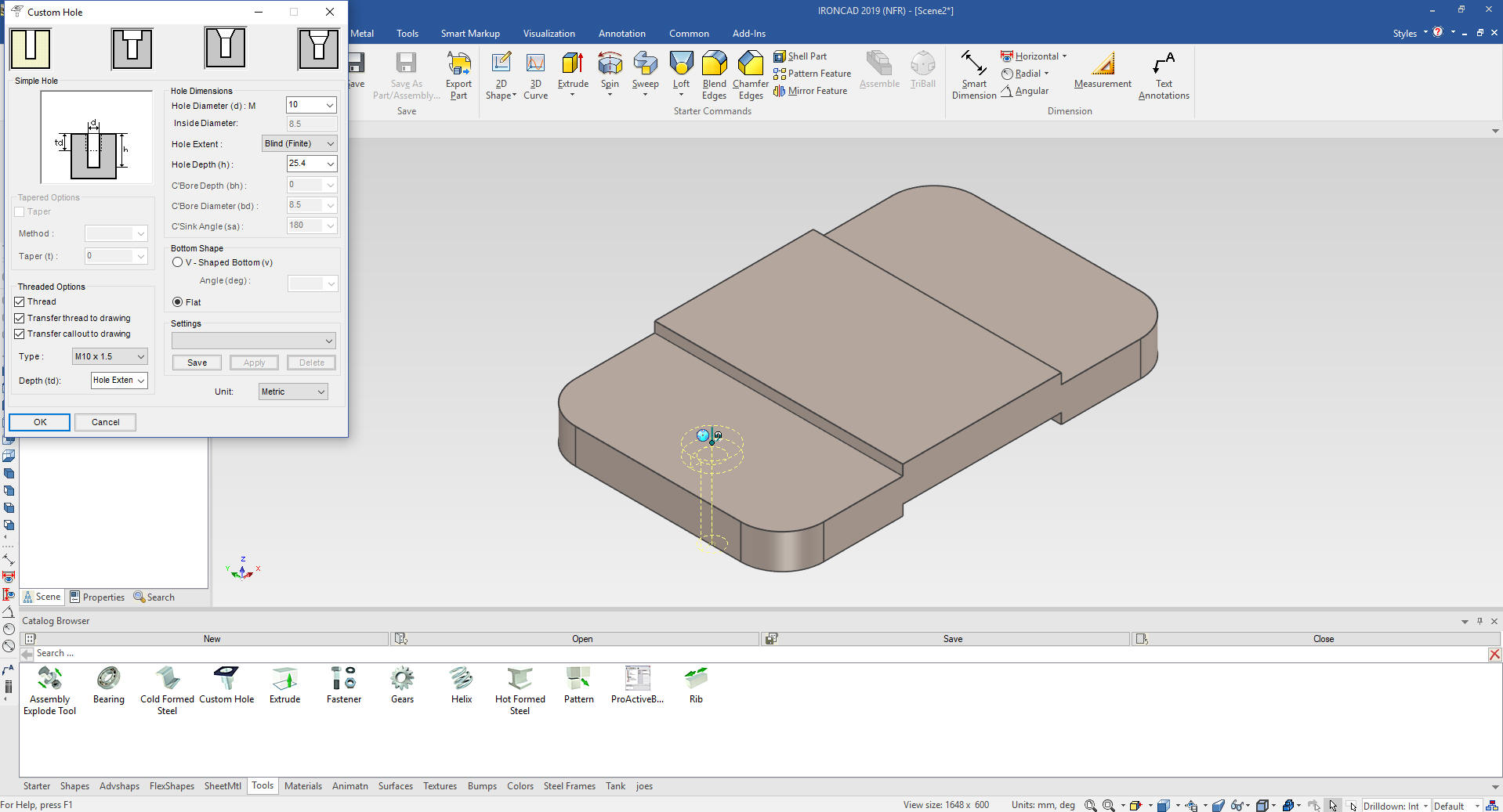
We will put in the 4 M10 holes. We drag
and drop a custom hole from the tool catalog to the mid-point as
shown. I can't believe it is as complicated to locate a hole in
Solid Edge.
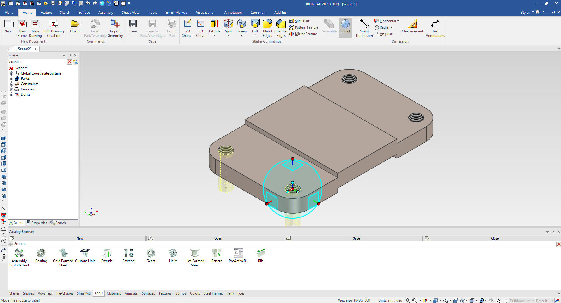
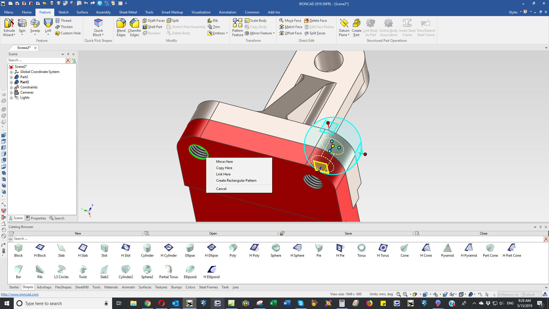
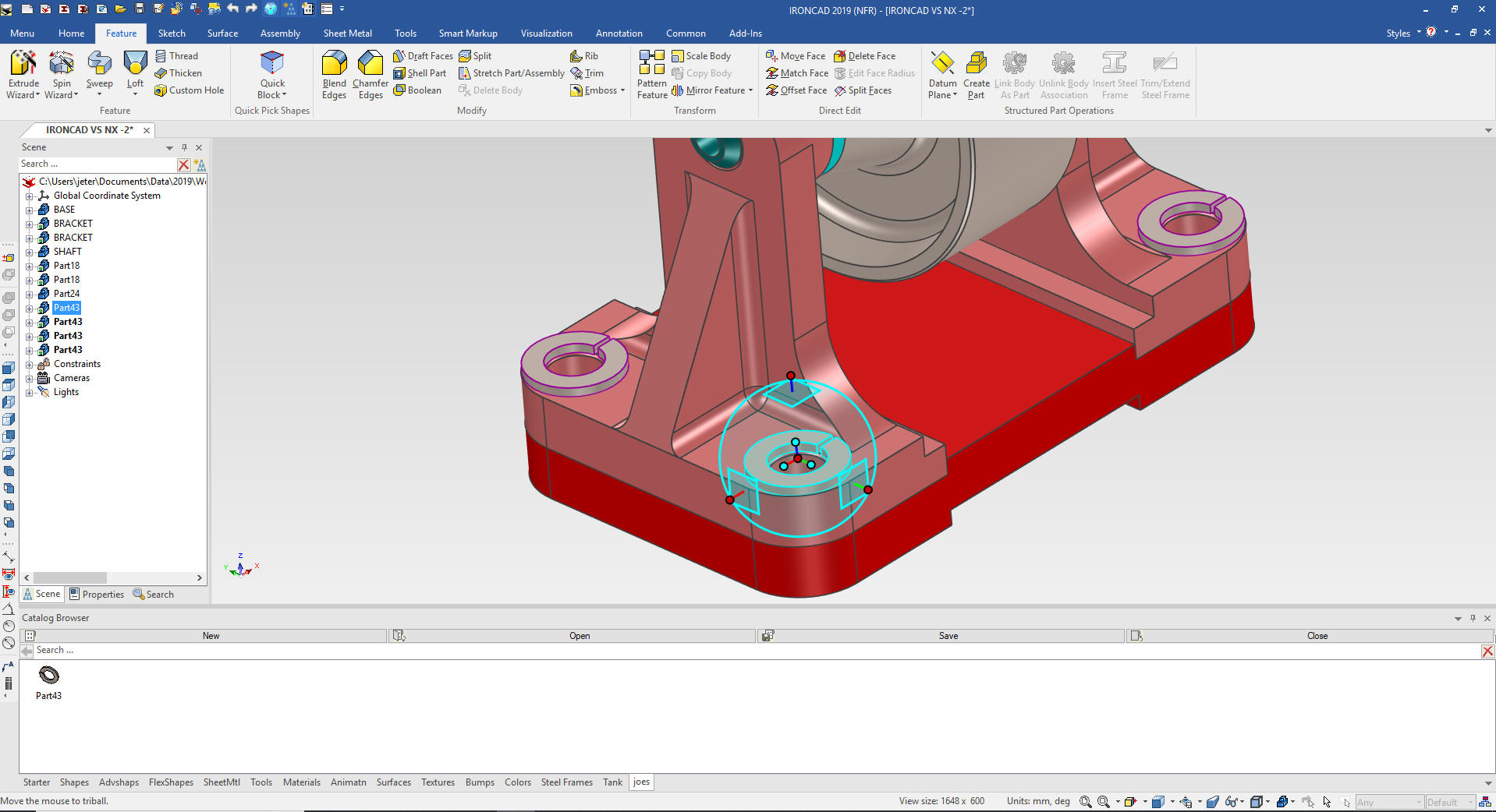
We locate the first hole then locate and
link the other 3 holes using the triball.
The Triball is used throughout the design. I can manipulate
features, parts and assemblies.
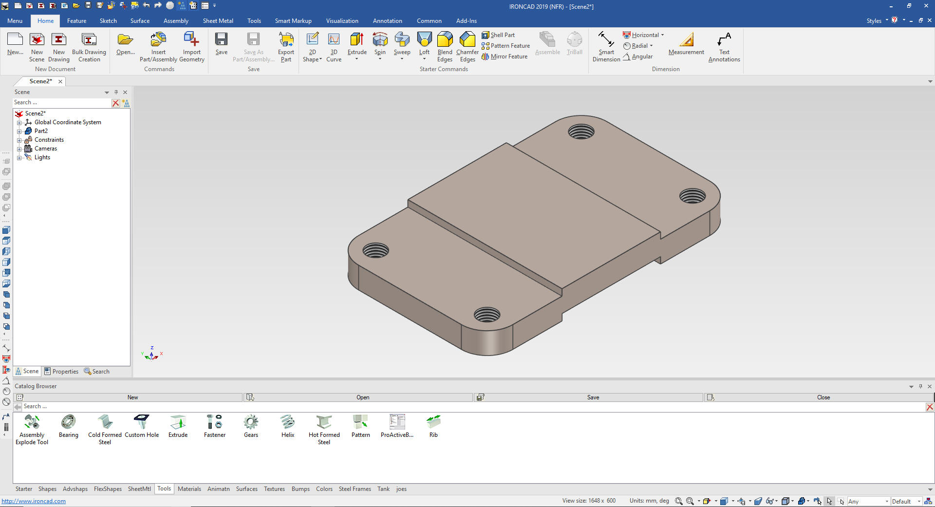
We name the part base and we are done.
No sketches were used.
IronCAD was designed from the ground up
for top down or in context design and has many function that make it
much easier.
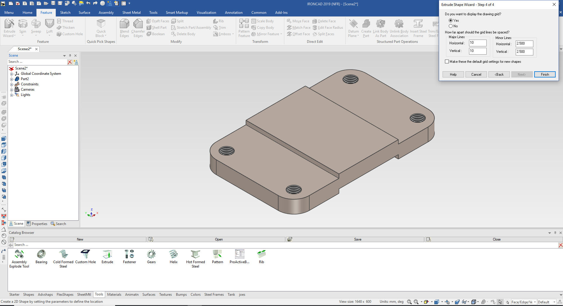
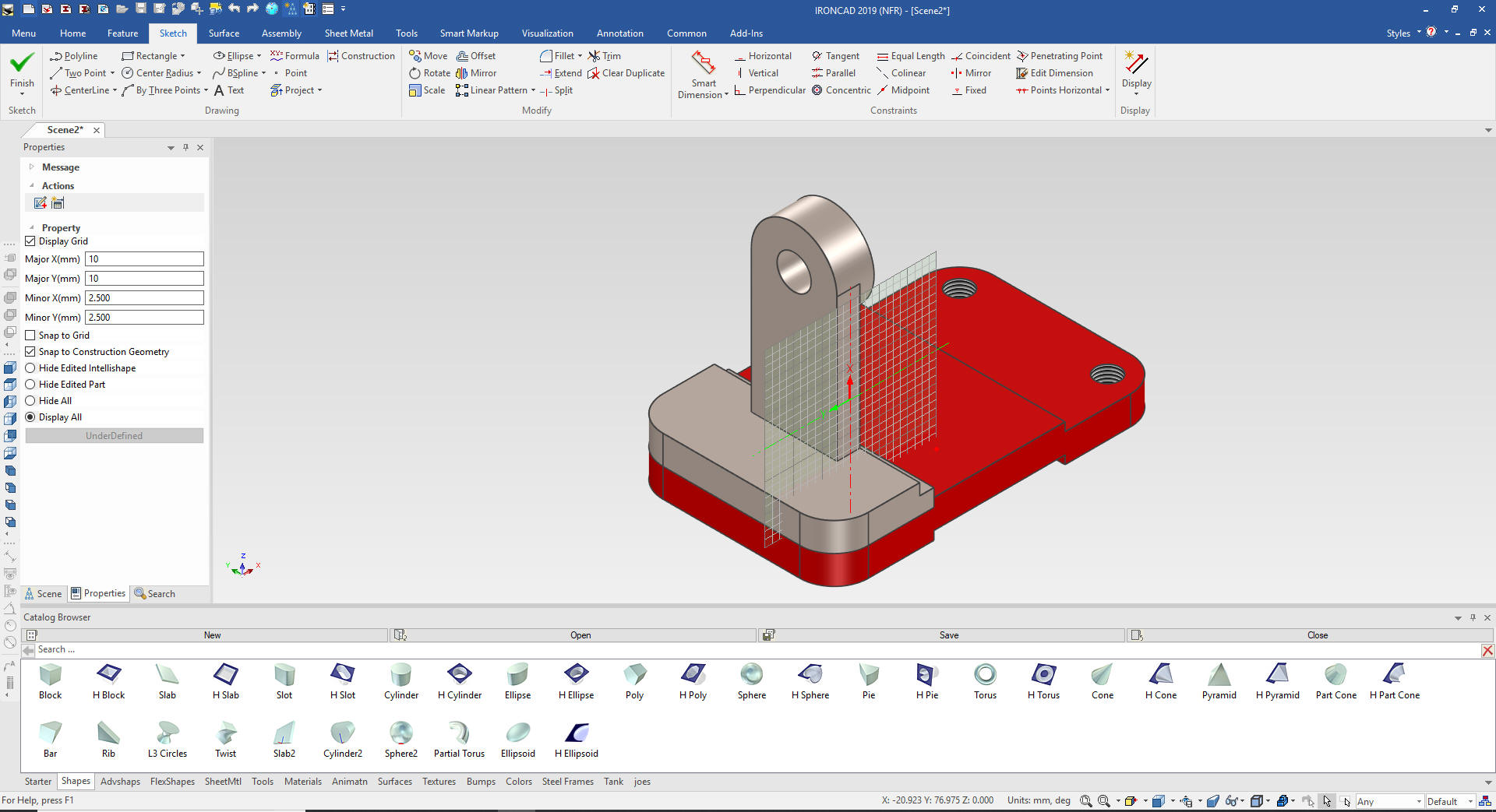
One of those functions is the Extrude Wizard
which will use to start the bracket. We select the Extrude Wizard
and select the front top face and in the dialog box we pick stand
alone and set it for 10mm.
We select project from the sketch menu
and select the front top face and that creates our sketch. We do not
want the holes so we delete them.
Yes we use sketches in our
designs. The Extrude Wizard is one of the main tools in in context
design in making mating parts.
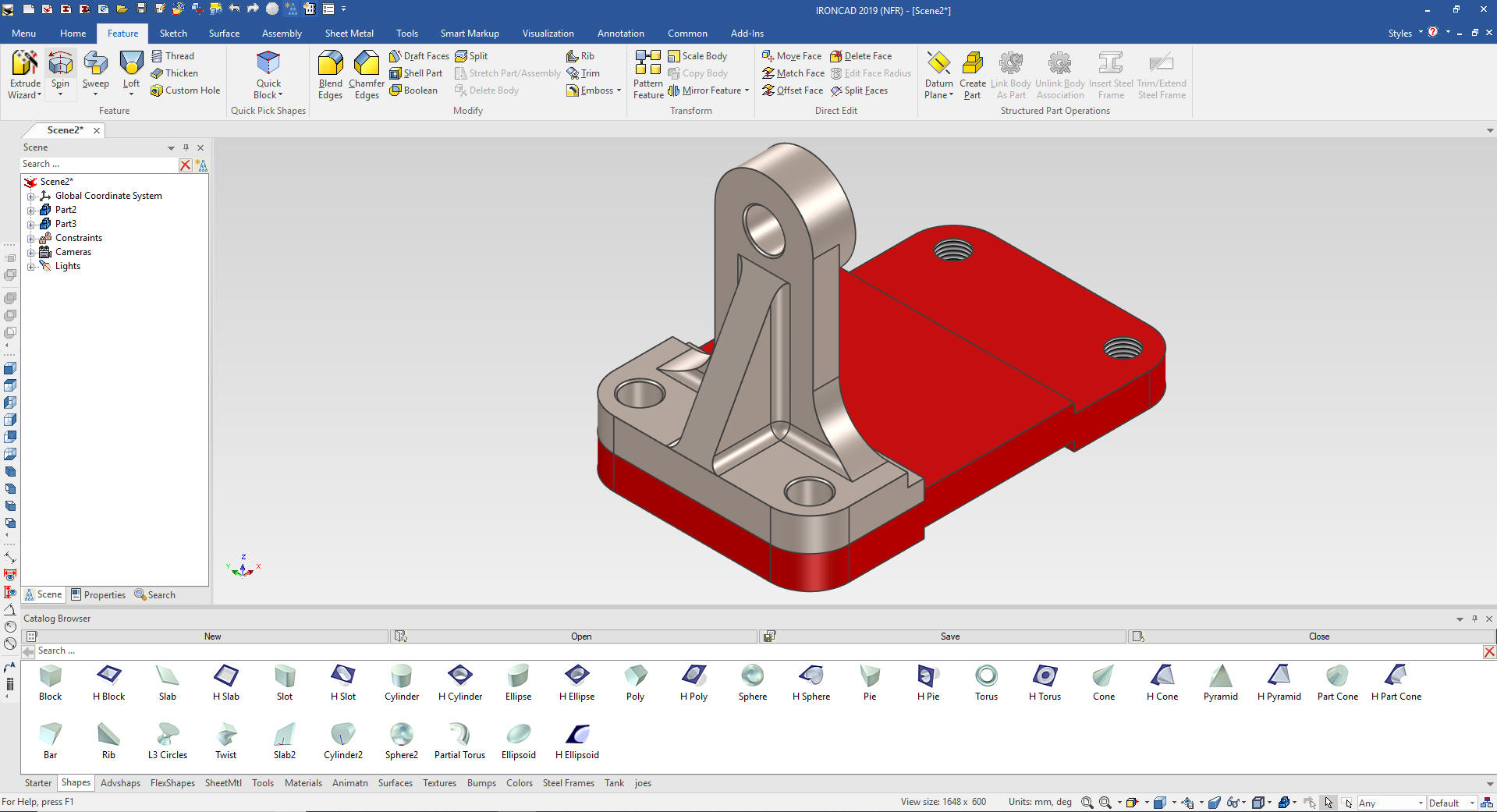
We just
select okay and we have the base for the bracket.
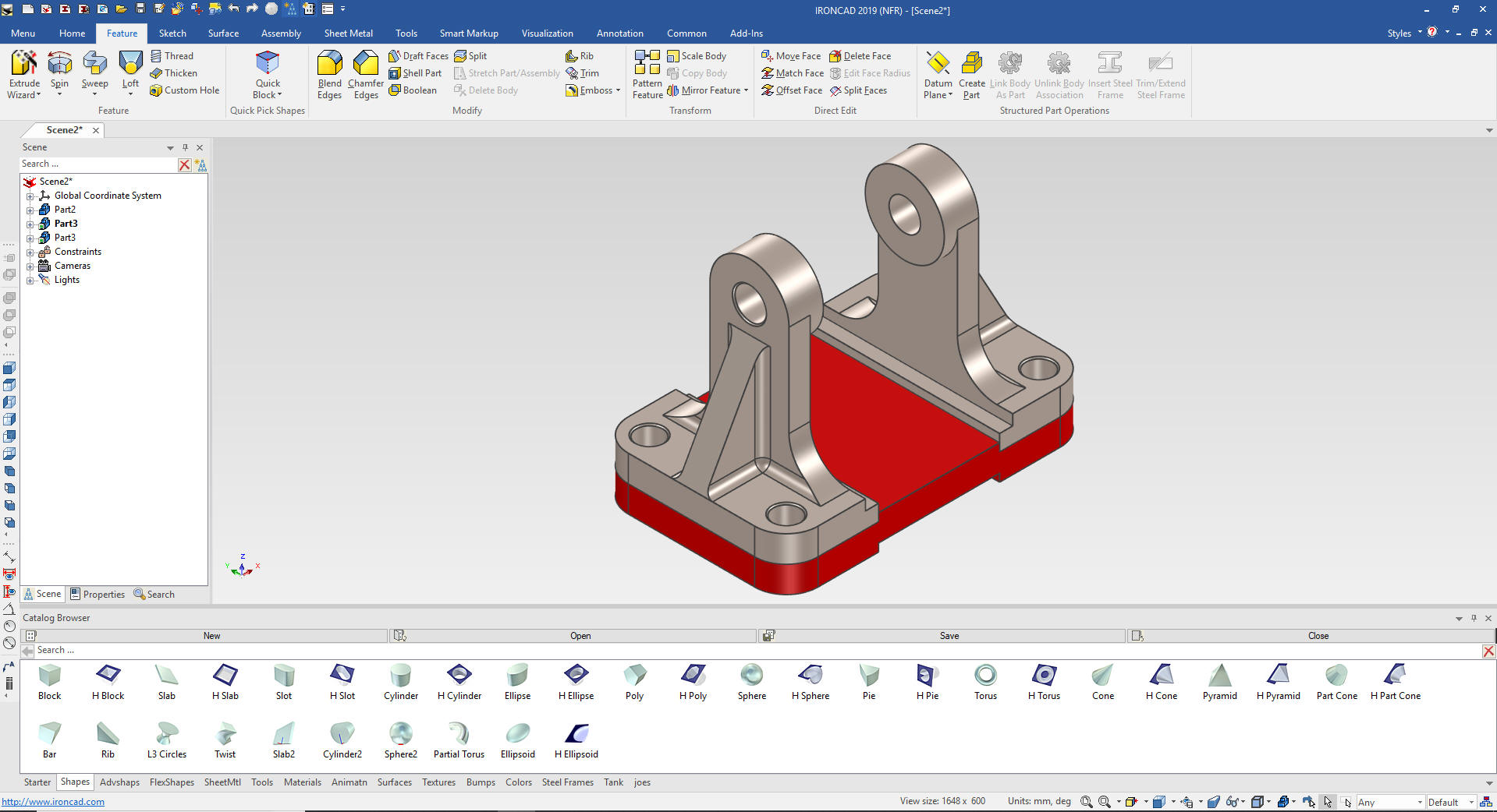
We change
the color on the base for clarity.

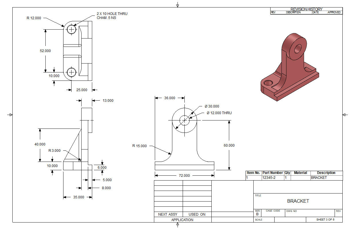
We
add the front cut by dragging and dropping a hole block to front
edge of the bracket base.
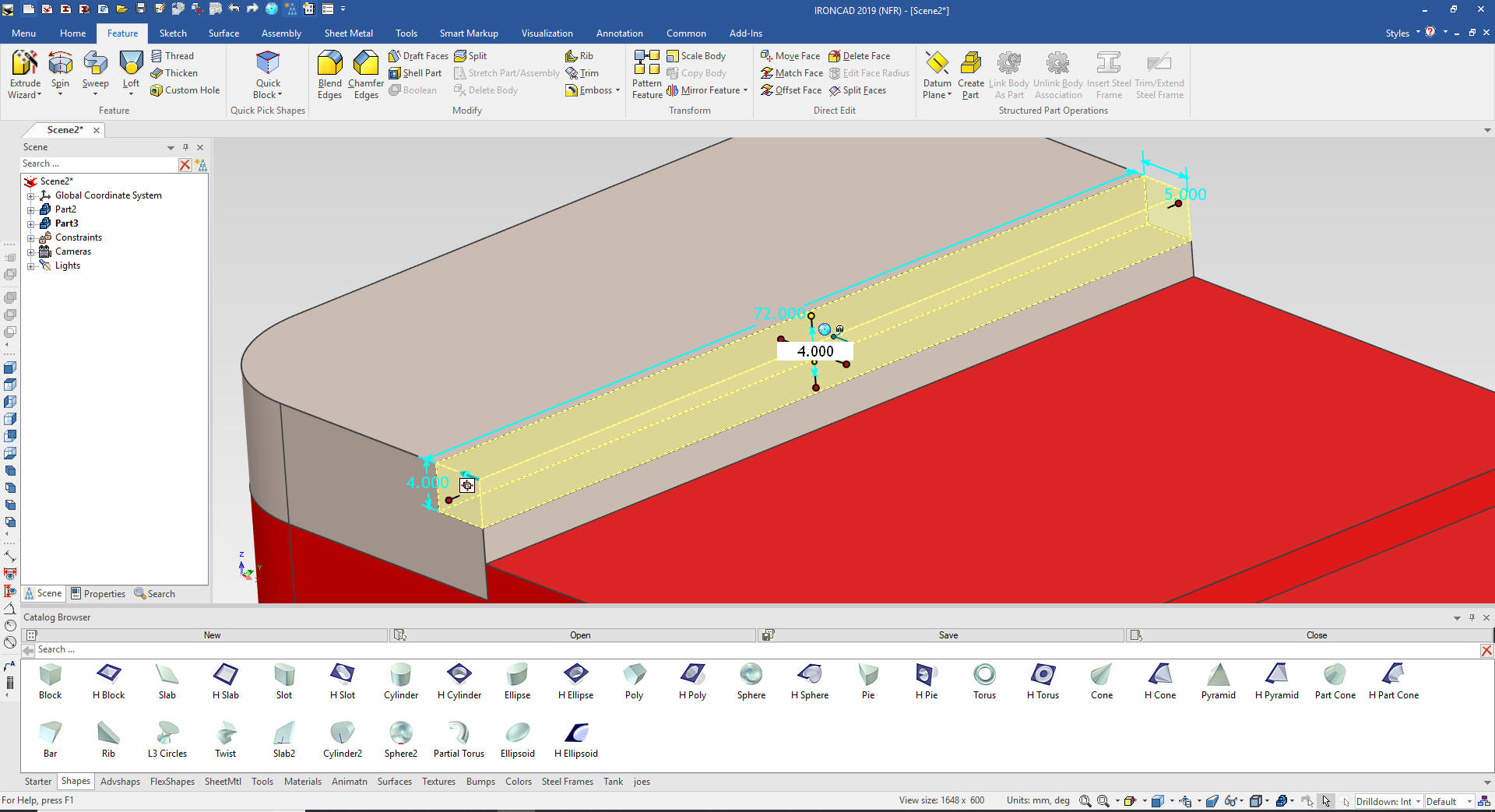
I
drag and drop a block to the edge of the related face of the bracket
base and size the block.
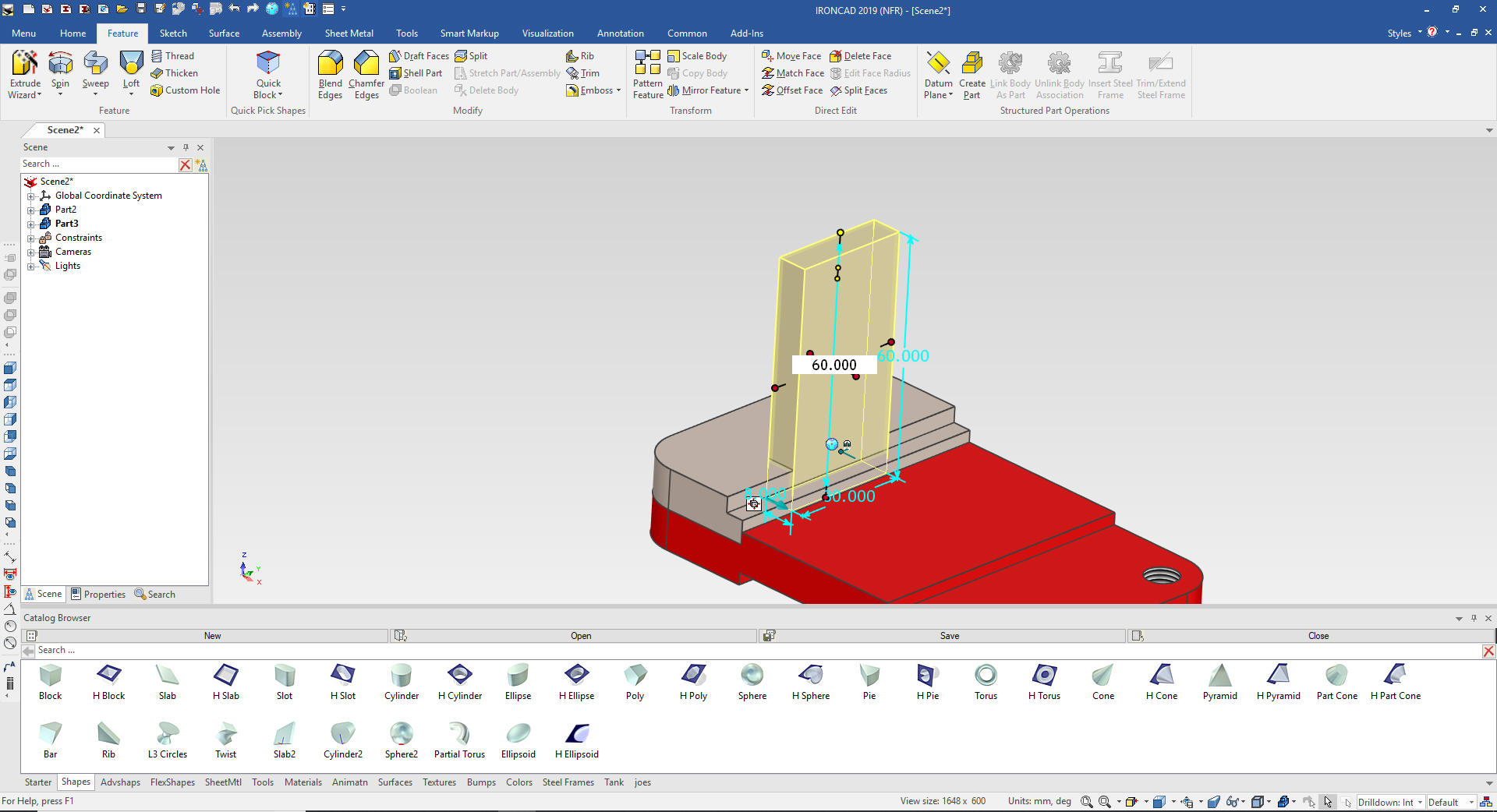
I
will drag and drop a cylinder on the upper edge of the block.
IronCAD knows depending on how the faces are viewed how to orient
the dragged intellishape. We then size the cylinder.
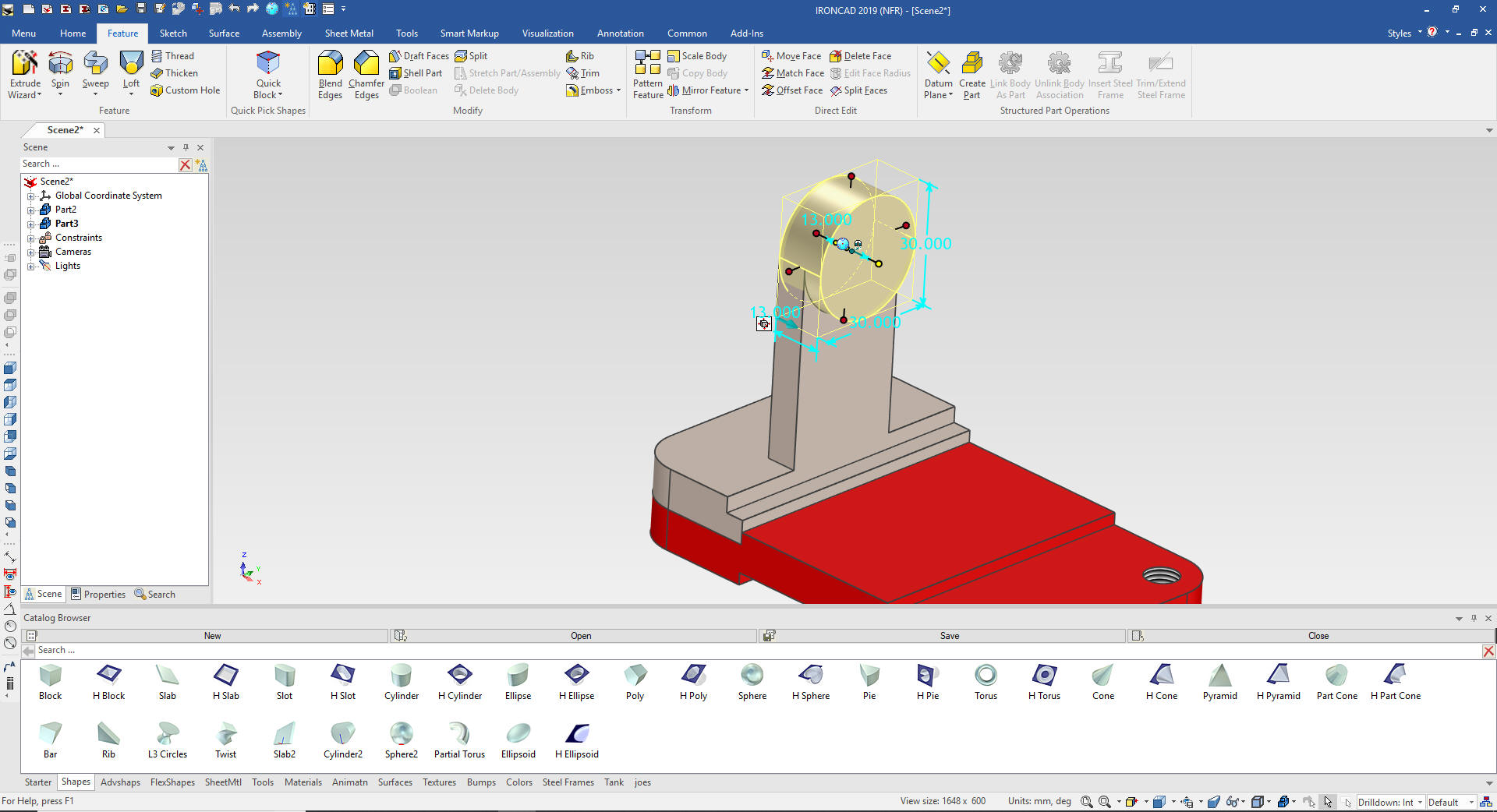
We
add the hole by dragging and dropping a cylinder to the center of
the boss and sized.
And
now for the rib. We again use the Extrude Wizard to add a feature
not to create a mating part. IronCAD also has a standalone sketching
function for development or for using .dxf/.dwg 2D graphic imports.
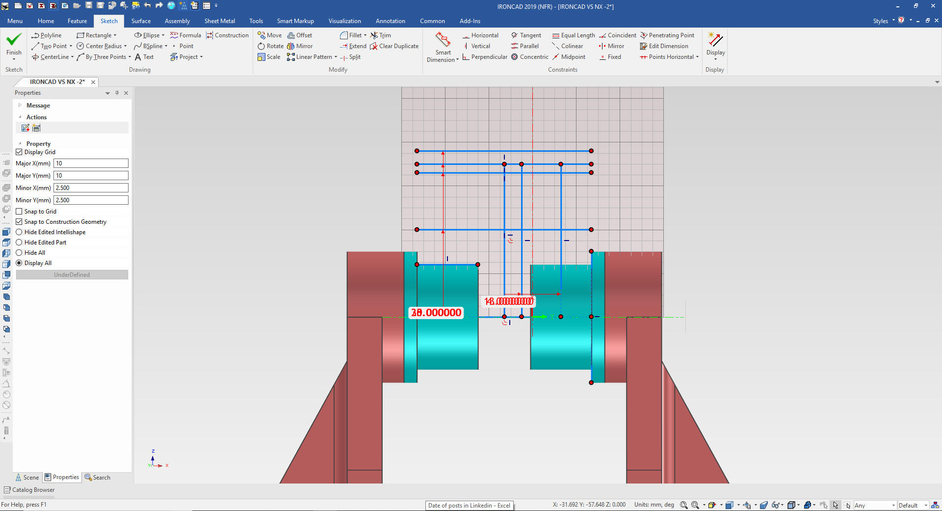
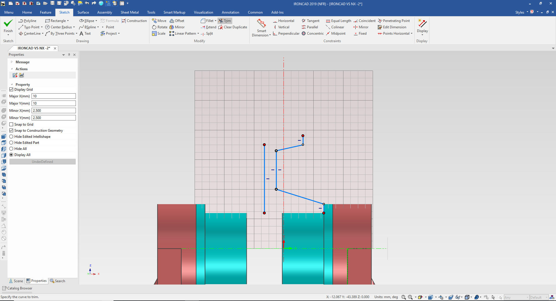
We project the relative edges necessary to create the rib.
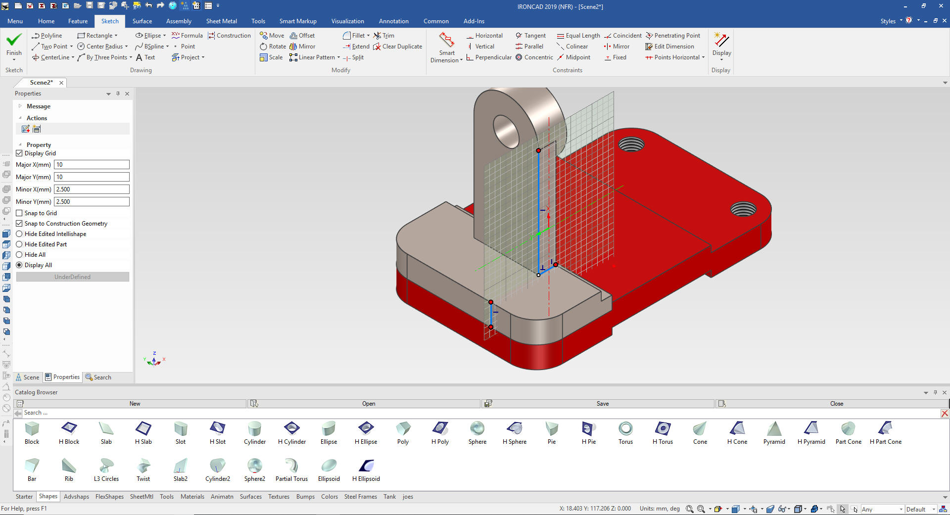
We edit the vertical line to 40 and extend and trim the bottom line.
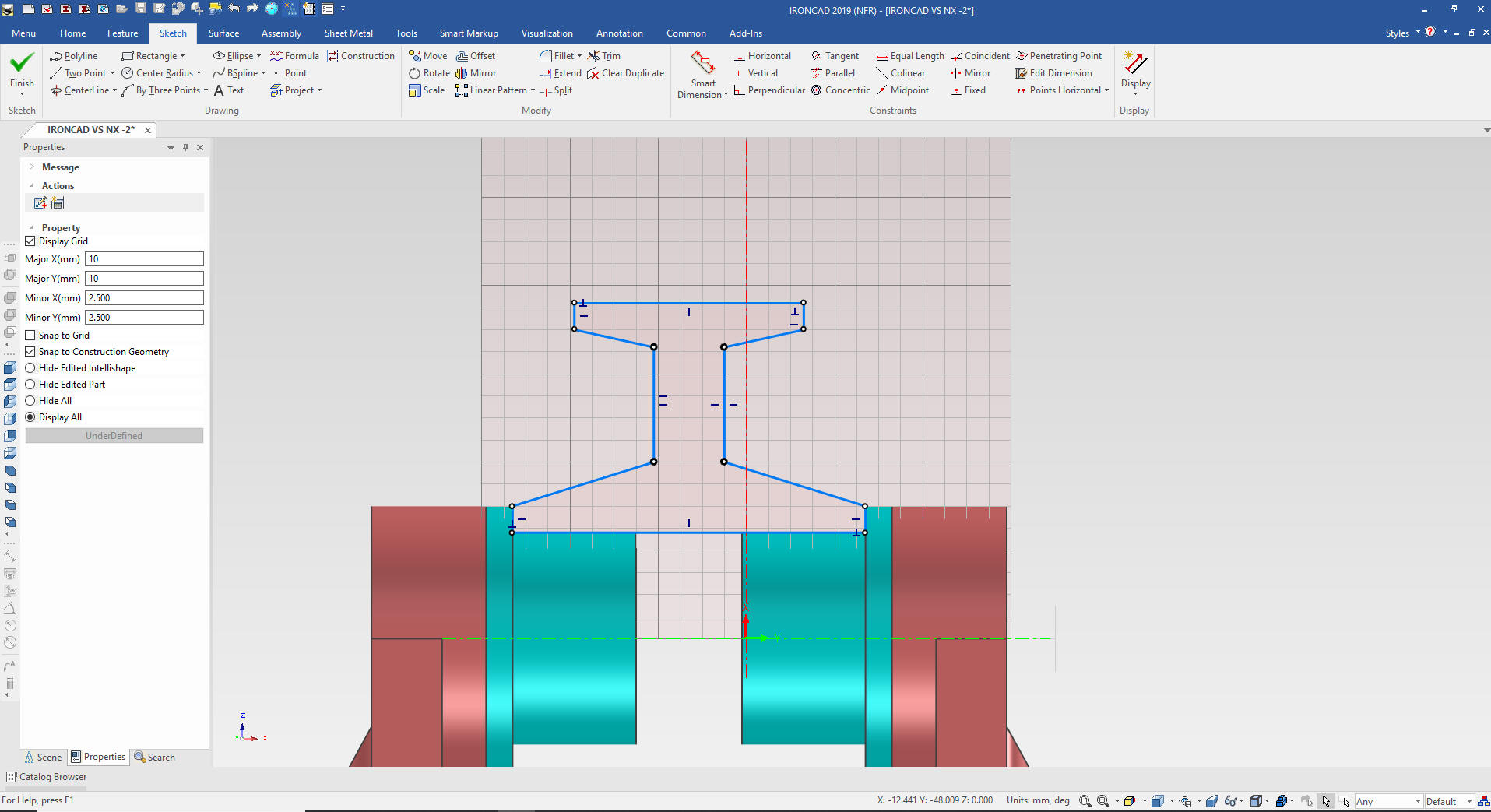
Delete the construction line and connect the dots. A red dot means
then lines are not connected and the sketch will fail.
Note:
I was talking to one of my associates and realized I could have drag
and dropped a rib intellishape on to the part, eliminating the need
for the sketch!

We
select okay and we locate the rib with the triball.
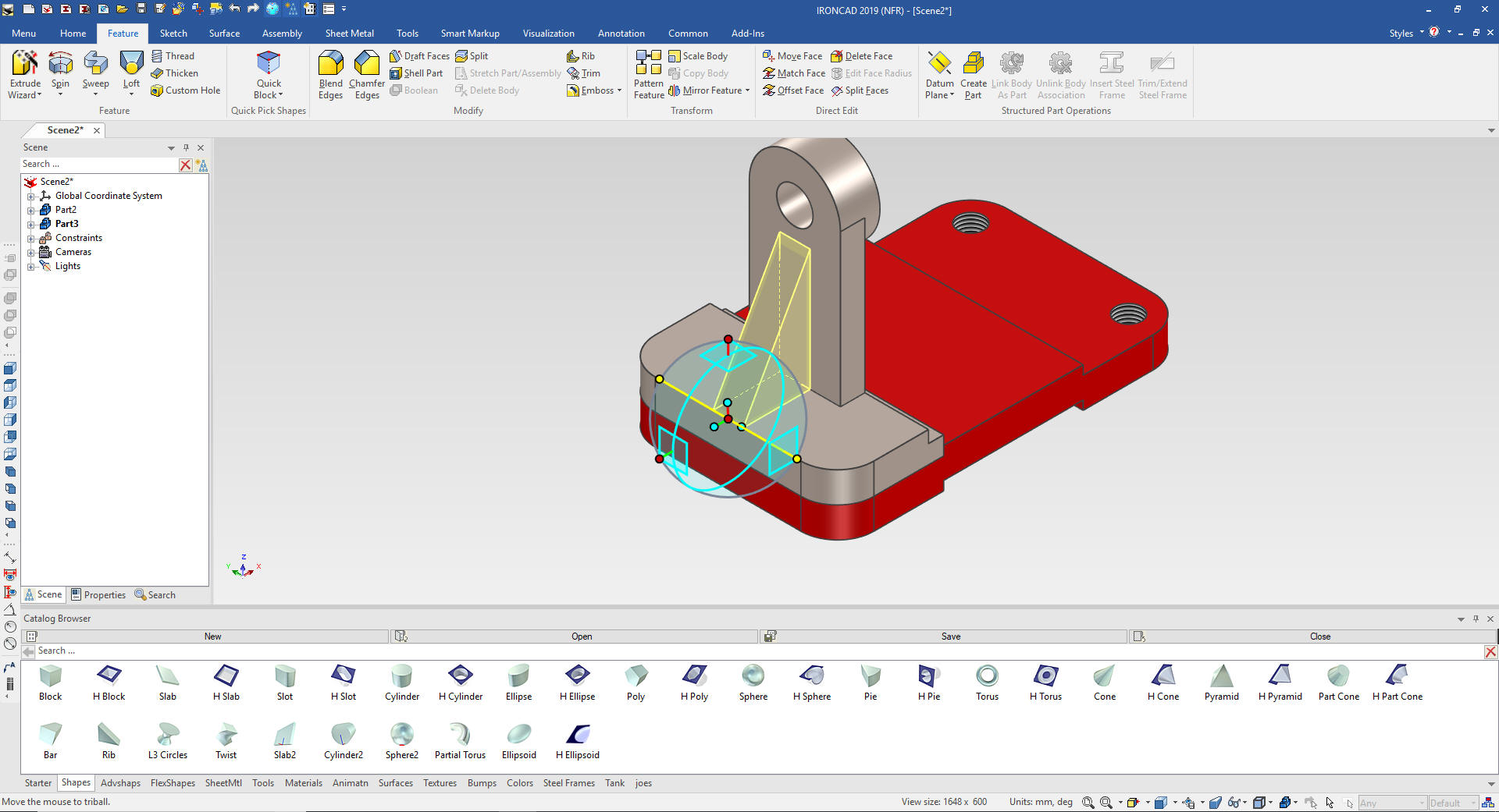
We now
put in the blends.
Now
for the holes.
I drop a 10mm hole on the top face of the
bracket face.
I
could have made these with the original projection but I want to
have them linked for use later.
I will now turn on the
Triball, locking the feature to the plane will move it the center of
the base plates hole than use it again the same way to link it and
use the base plate hole to locate it.
Add
the chamfers and we are done.
We
will link rotate and locate the bracket at this time.
We
change the color of the bracket, since they are linked both change.
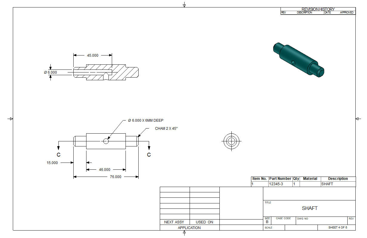
Now for the shaft. We drag and drop a cylinder to the front face
of the aft bracket
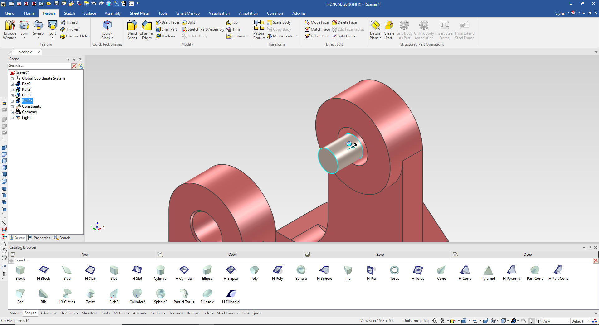
We
now size the long portion of the shaft. We size it, add the chamfers
and the hole.
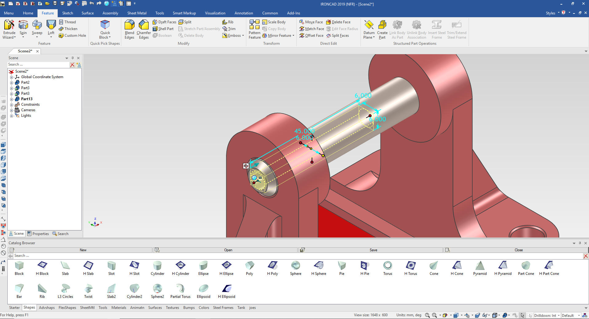
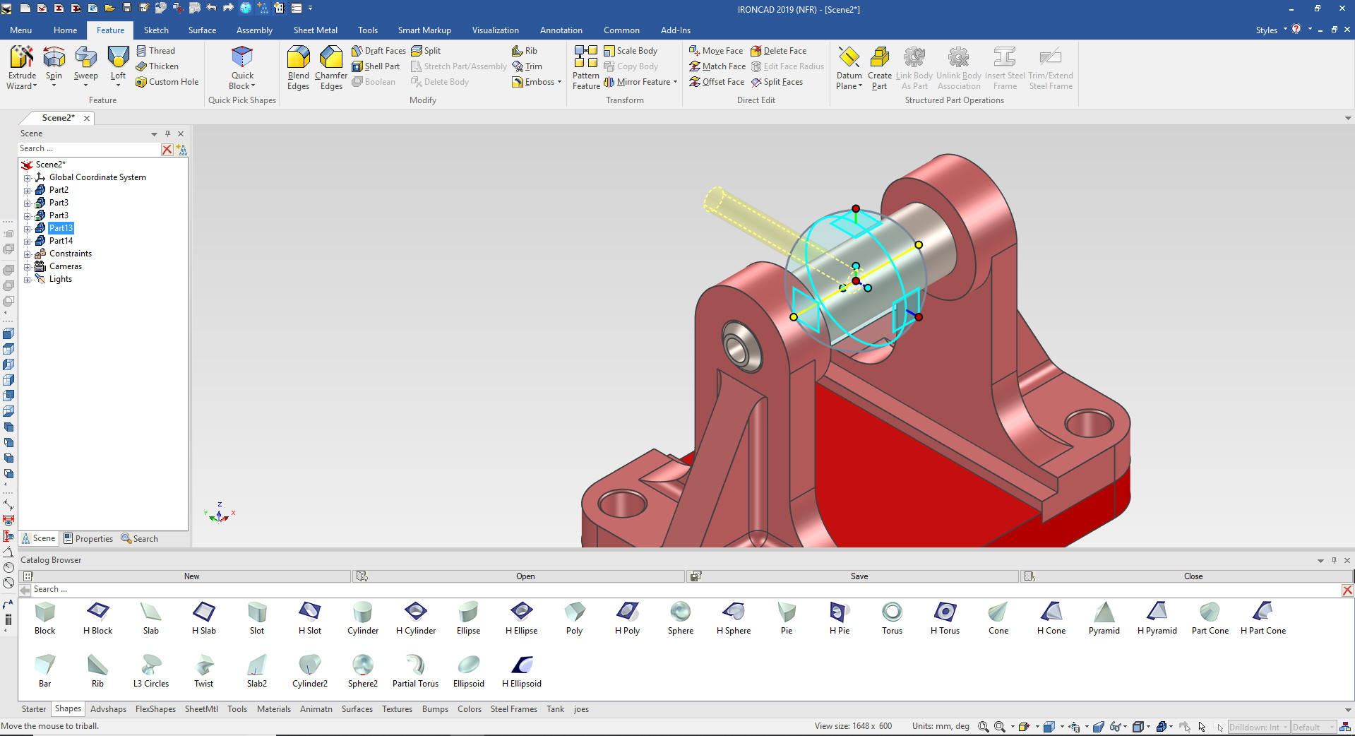
Now
we drop another cylinder that will become the larger center portion
of the shaft.
We
just size it an pull it to the mating faces. Now for the hole I will
use a little trick. Since it is the same size as the end hole I can
just take the triball and rotate it 180 degrees and copy it and move
it. I could do this with any size hole.
We
now just size the length of the hole and we are done with the shaft.
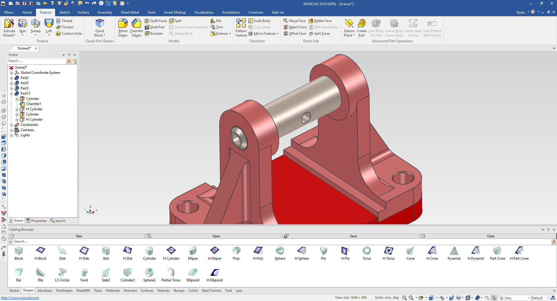
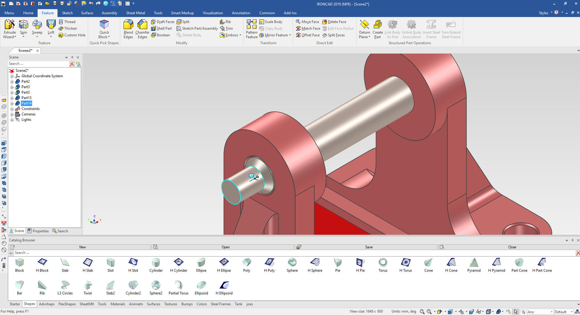
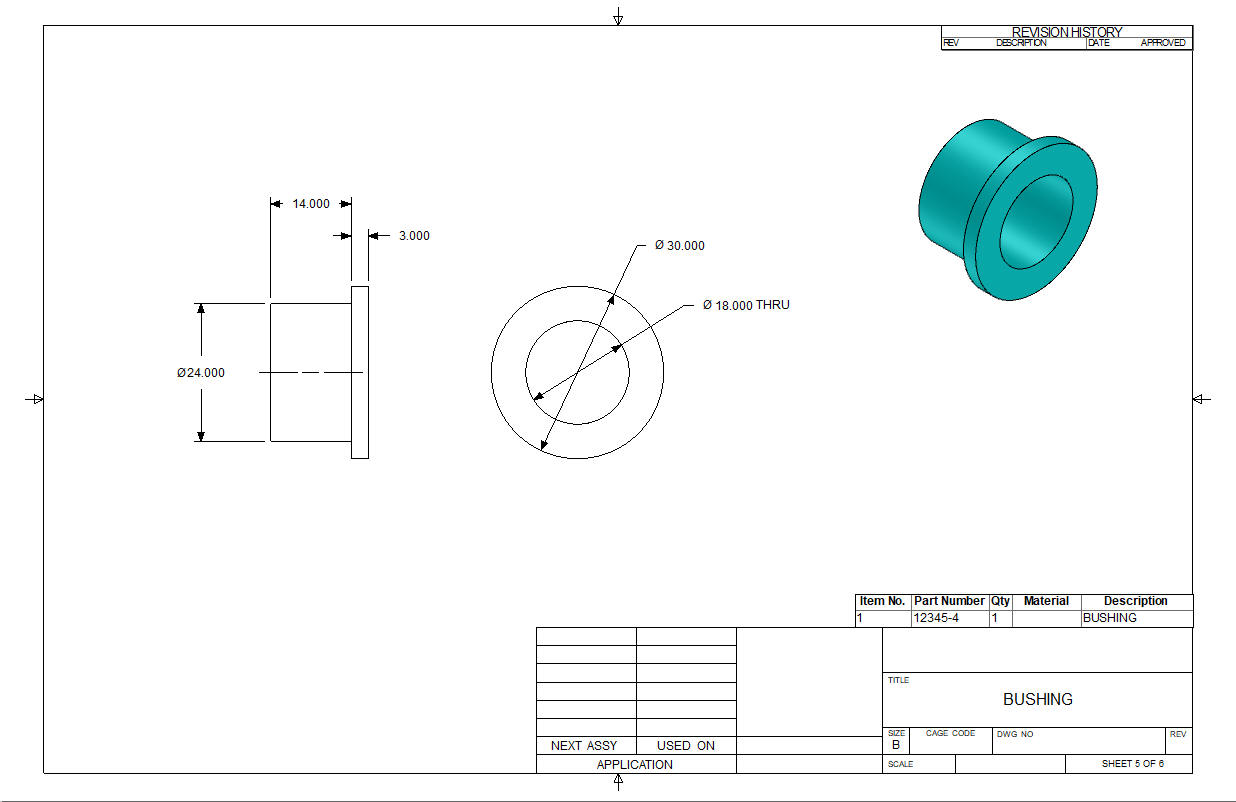
Now for the bushings. Notice I am not worried about assembly. We
will create the assemblies later.
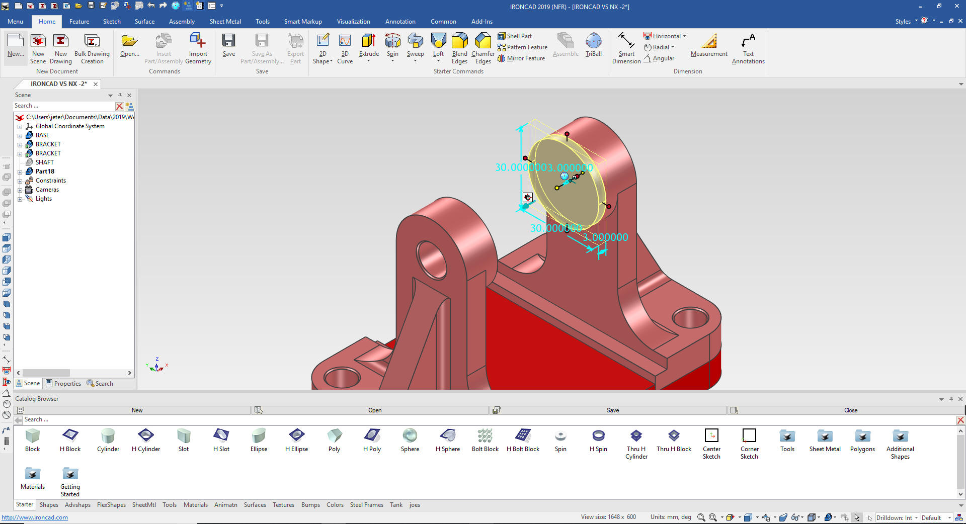
We will hide the
shaft and drag and drop a new cylinder to the center of the boss!
Now just edit the size box. The size box is the basic envelope of
the Intellishape.
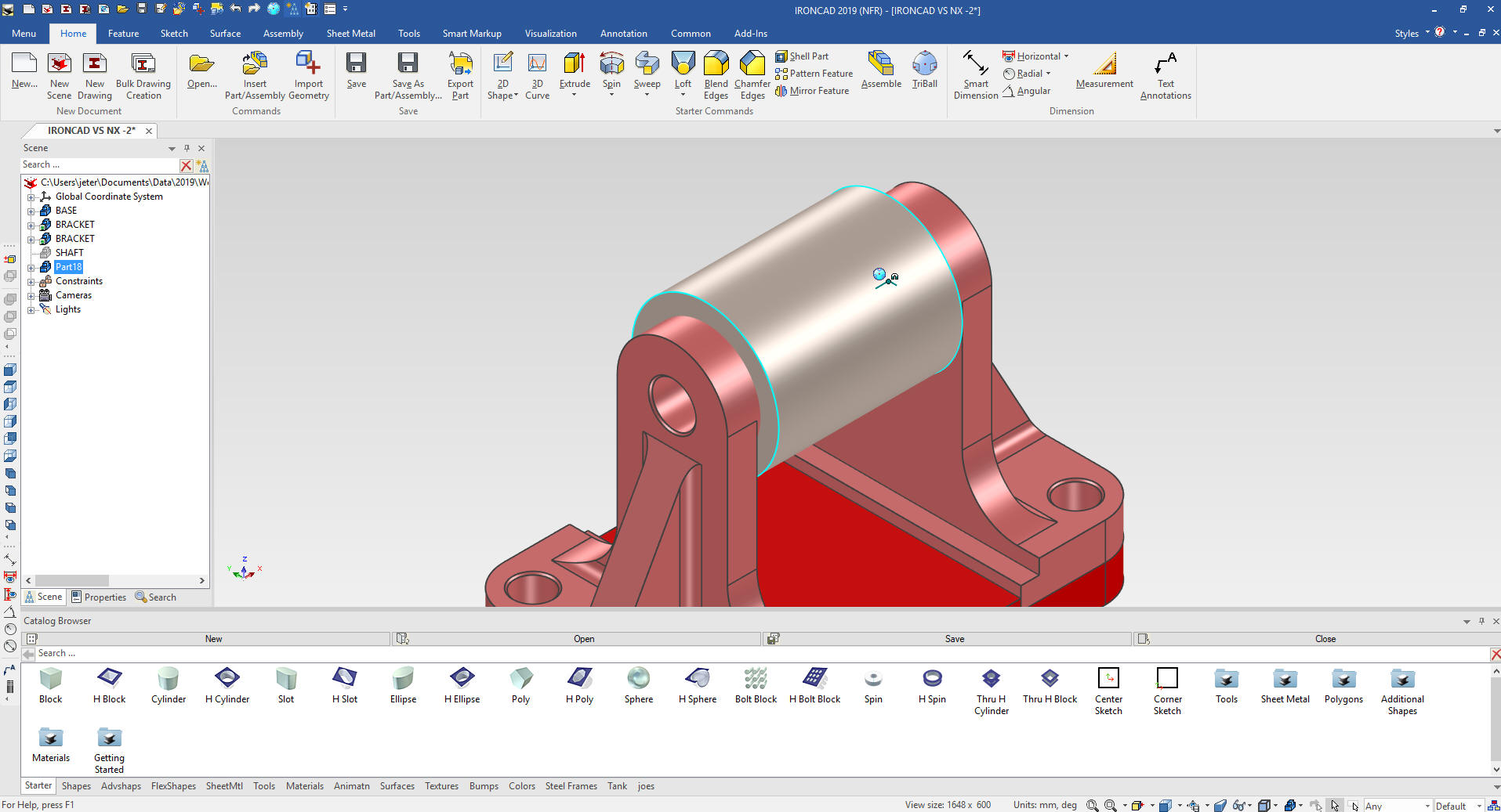
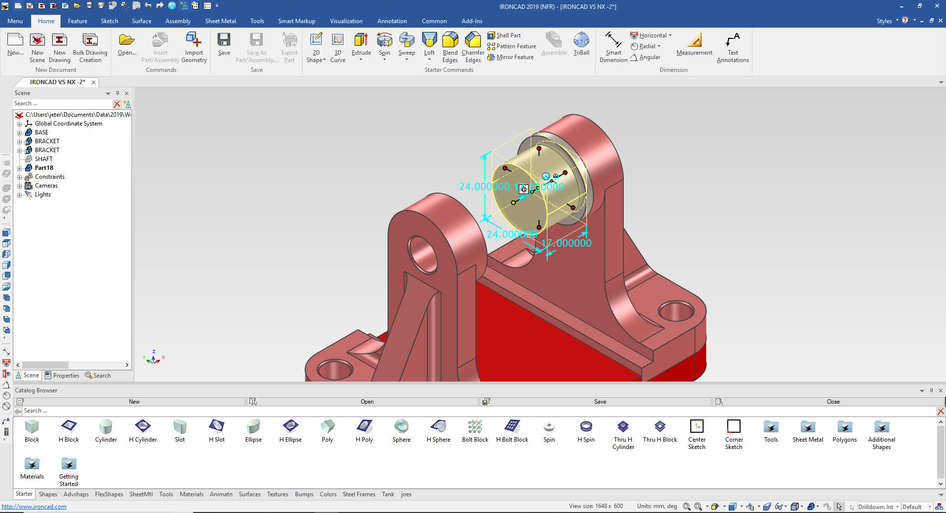
Now
we add another cylinder to the center and size it, but we will use
the left mouse button that automatically makes it part of the
bushing. I pull the aft handle to the aft edge of the original
cylinder and then set the 17mm length. That way I don't have to
worry about subtracting or adding.
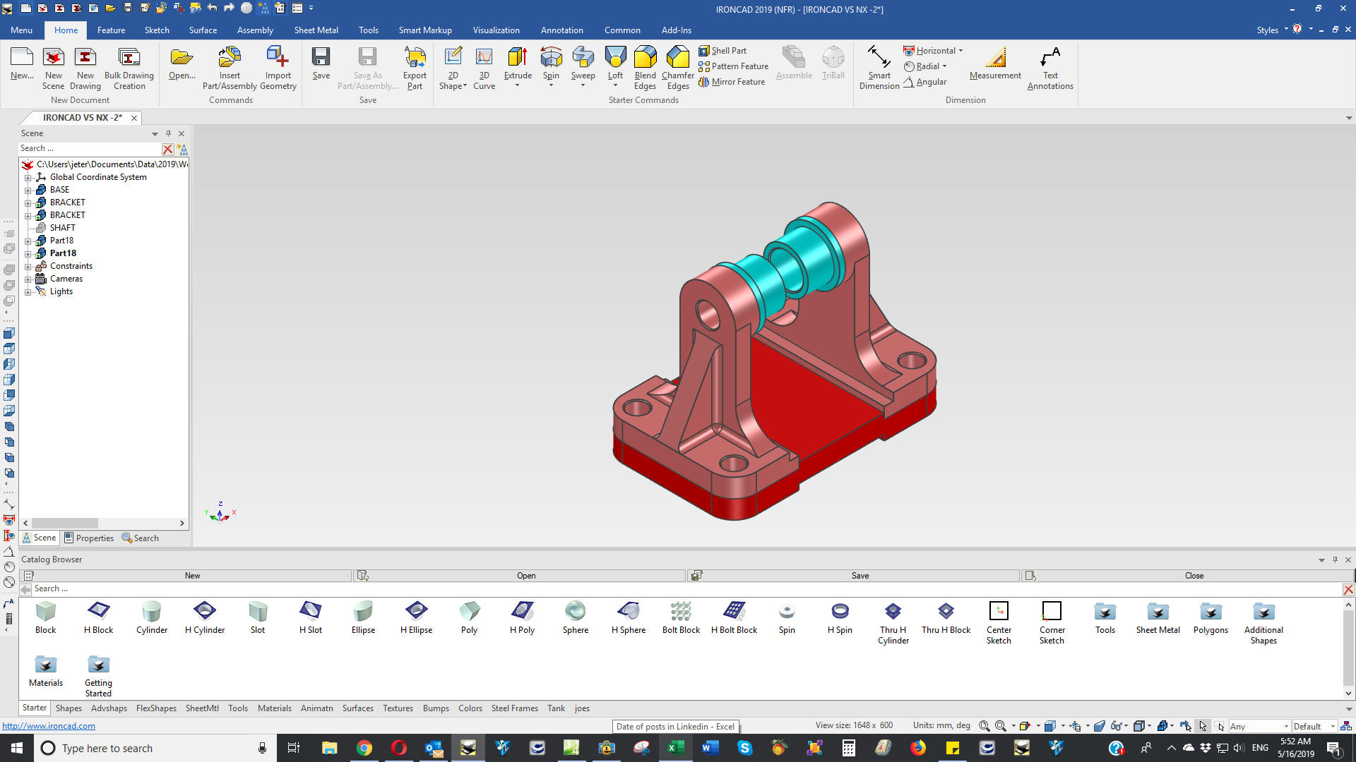
Add
the hole and the chamfer and we are done with the bushing. We then
use the triball to link and rotate into place and change the color.
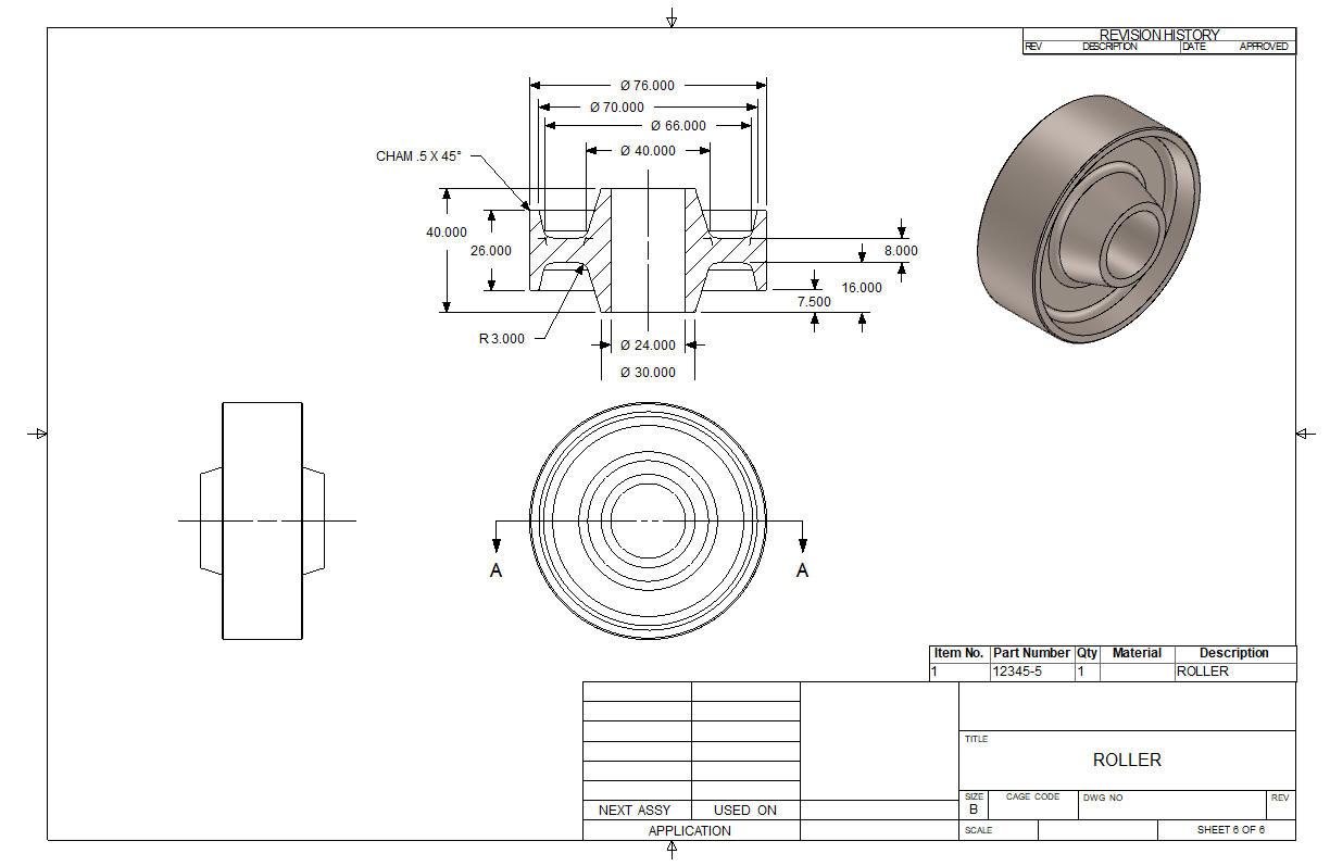
Using the Spin Wizard I locate a sketch and set to 360 degrees.
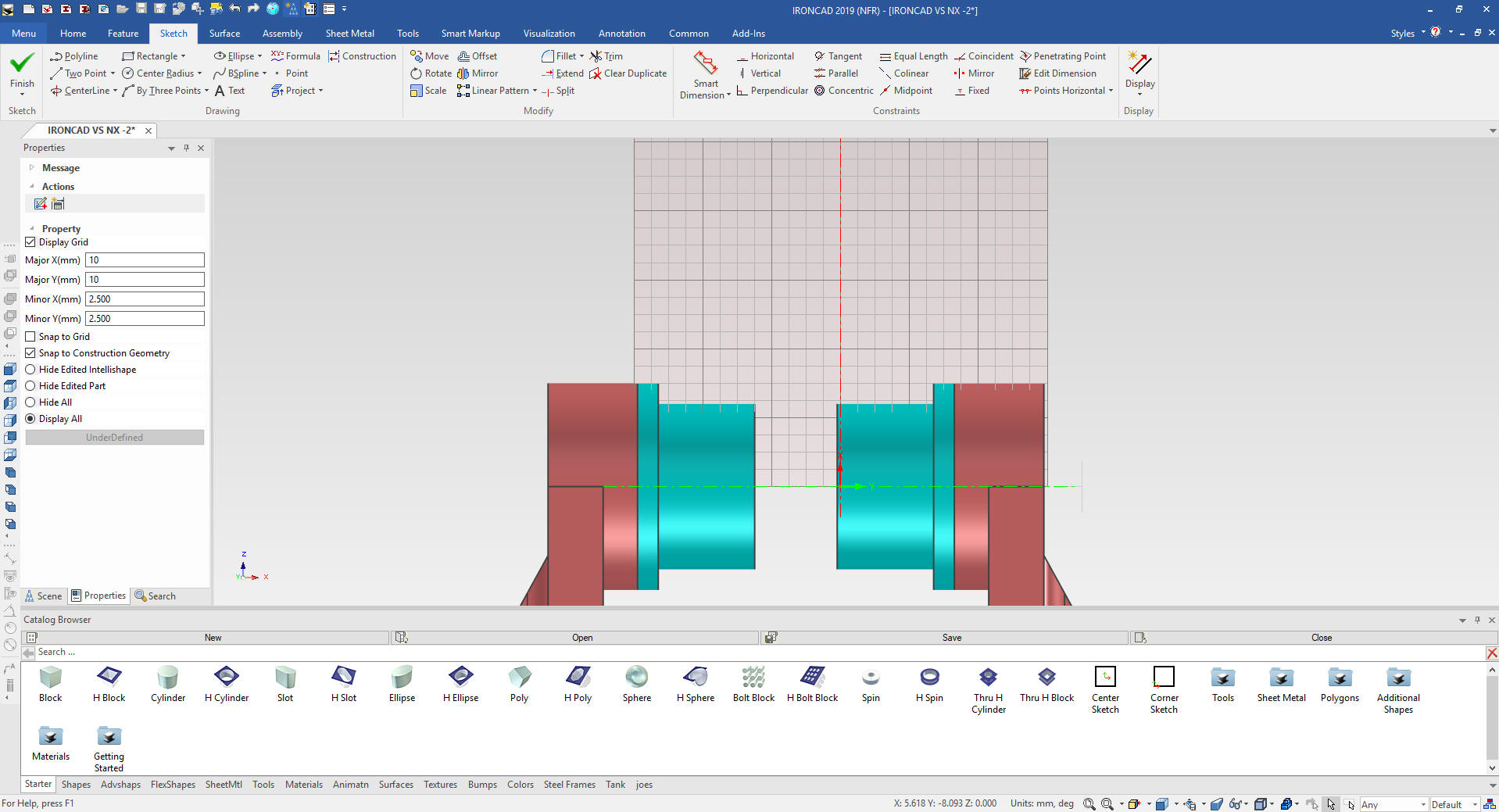
I
have created my reference entities. I will use StreamLined
Sketching! We can use constrained sketching but I have found like in
the Solid Edge presentation it is a bit more complex. Also I have hid the
catalog for more space in the scene.
Learning IronCAD! Lesson 3
Streamlined Sketching
(Unconstrained Sketching)
Why do we call it a Scene instead of a workspace? IronCAD was first released as Trispectives, a graphics design package.
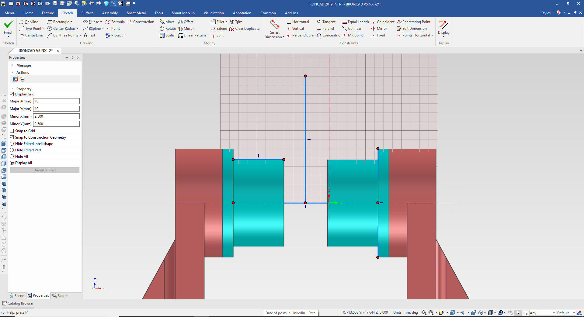
Now we will add a few parallel lines.
Now
we connect the dots and delete the referenced graphics leaving the
reference centerline.
We
mirror the graphics and add the lines and delete any reference
entities.
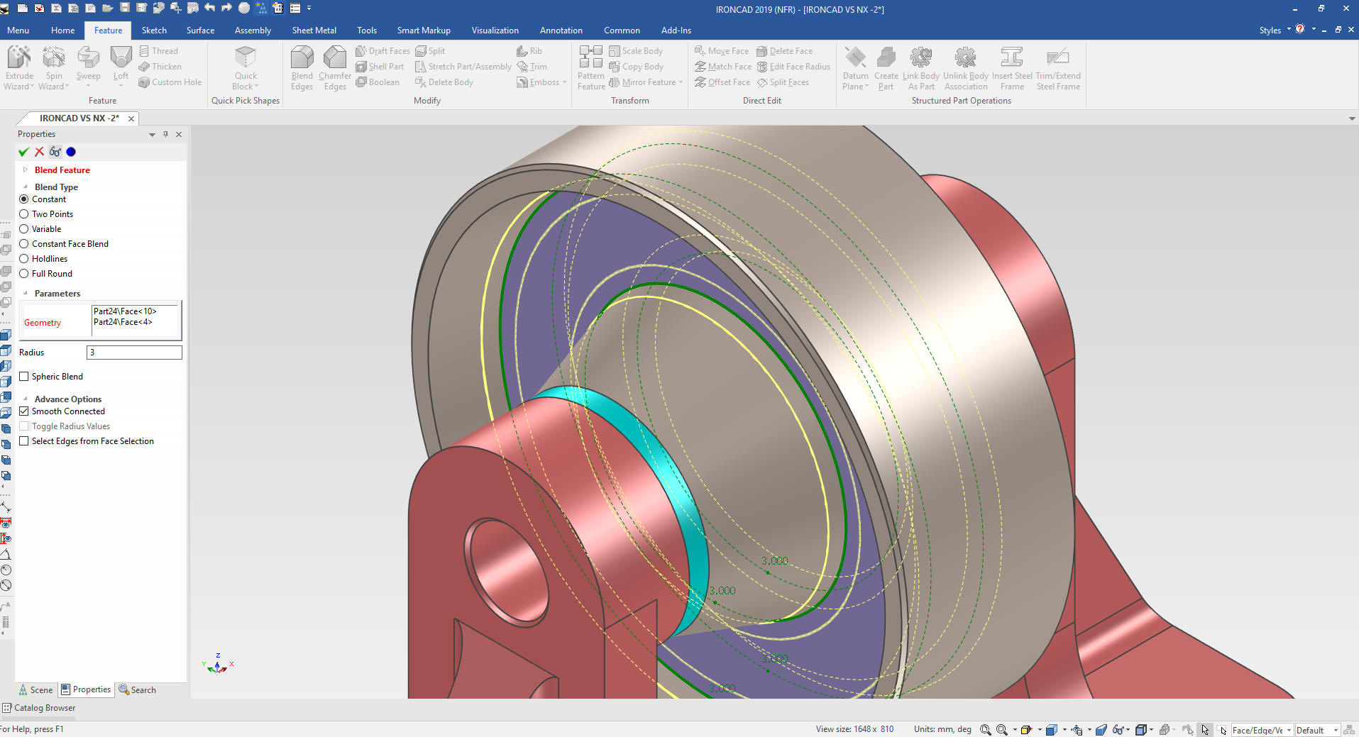
We
select okay and add the chamfers and blends, by selecting the inside
face and we are done.
We
show the shaft and were are done done with our design. Now to add
the fasteners. We drag and drop the washer from a custom catalog
locate and link using the Triball.
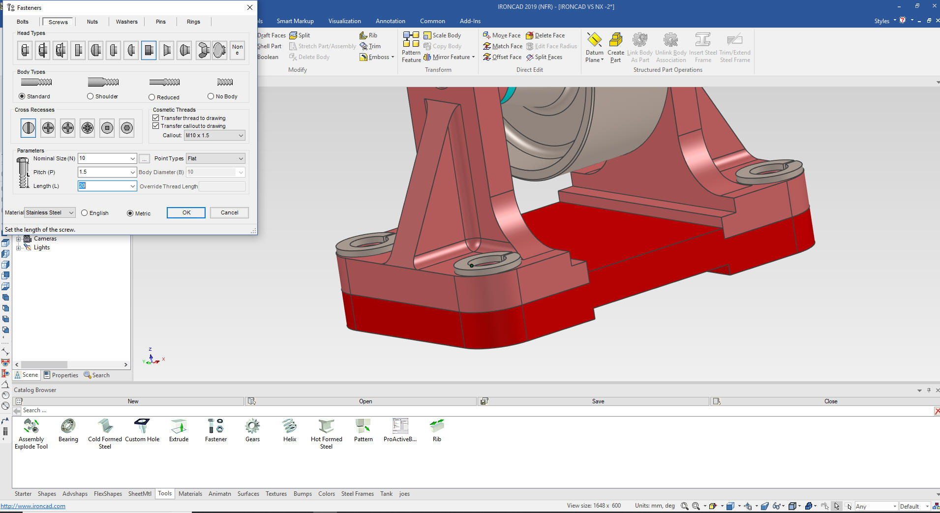
Now
for the screws screws. We drag and drop the screw from our fasteners
in the tool catalog and define it in the dialog box.
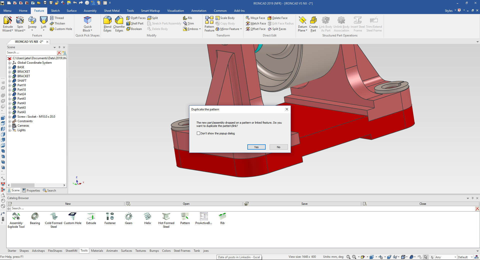
We
have the option to create a screw at all of the linked washers, we
select yes.
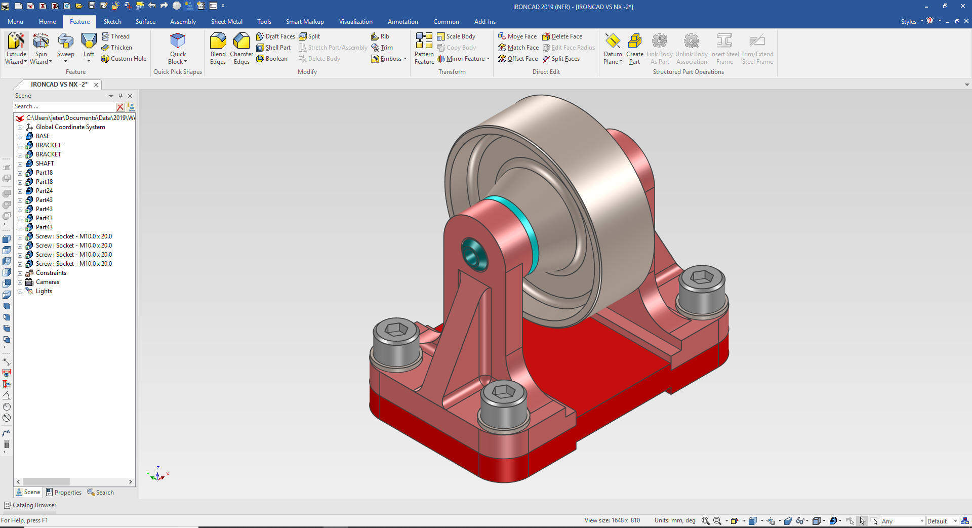
We
are now done with our assembly. All parts were designed top down and
in context in a single model environment.
Look through the
process again, these are all the steps to create this assembly.
Compare it to Solid Edge.
Making the drawings is a breeze. We just select the Bulk Drawing
creation, select the parts and IronCAD will generate the assembly
and the other 5 parts for detailing.
Think of the amount of
files created with Solid Edge the five parts and one assembly, if
you create the AIDs (Associated Information Documents (drawings))
that is a total of eleven files to maintain. IronCAD created two
files.
It is
very important that you look into how you or your engineers are
creating the parts. Streamline Sketching and Feature Based Modeling
is easy to learn and implement. It, alone, will increase
productivity 10X. Now, IronCAD with its unique integrated
history/direct edit functionality can increase your productivity
another 5X or more with changes! Again, time is money in
engineering.
More on Streamline Sketching and Feature
Based Modeling.
3D CAD Modeling Techniques
To experience this increased level of productivity, please download
IronCAD for a 30 day evaluation. Legacy data is no problem, IronCAD
can read the native files of all of the popular programs. IronCAD is
a great replacement for the subscription only Autodesk and PTC
products.
Give me a call if you have any
questions. I can set up a skype or gotomeeting to show this part
or answer any of your questions on the operation of IronCAD. It
truly is the very best conceptual 3D CAD system.
TECH-NET Engineering Services! | |