ZW3D vs Catia Lesson 3 Assembly 3D Modeling Techniques DefinedTrue Top Down Assembly/In Context Design vs Separate Part DesignWith Streamlined Sketching/Feature Based Modeling In a
Multi-Object Design Environment One Single File compared to Thirty??
Attention: Boeing, Airbus, Gulfstream,
Bombardier and other users of Catia 5 and those that are using
the other major Pro/e (Creo) paradigm based systems.
This
comparison shows how convoluted and expensive the Catia 5 design
environment is. The Catia 5 presentation creates:
10 separate
parts 10 separate AIDs (drawings) 4 sub-assemblies 4 sub-assembly
AIDs (drawings) 1 top-assembly 1 top-assembly AID (drawing)
30 separate files to maintain.
AID (Associated Information Document)
looks like a drawing but is made from views generated from the 3D
model incorrectly called the "2D Drawing"
ZW3D with its
Multi-Object
environment and integrated documentation mode:
1 File, Yes only one file!
Both still
have to create released models (parts) only and AIDs (drawings) as PDFs.
Now even with PMI you are still handling 15 files. If the
assemblies can even be done as a PMI.
Does anyone ever wonder
why we have such an unworkable PLM/PDM system?
Watch as I
create the models and sub-assemblies in a multi-object environment
using top down/in-context design as the Catia presenter creates each
part separately with constrained sketching and painfully inserts them into
each assembly.
It is not only the system that is the problem it is the standard
design process of "constrained sketching", you can see the increased
productivity in what I have coined "StreamLined Sketching and
Feature Based Modeling".
The
difference in design productivity is stark. Even the most uninformed CEO,
VP of engineering, Engineering manager and expert user can not deny
the advantages.
Yes we have to revise how we do and archive
our native engineering and documentation. But it can be hugely simpler and much
more cost effective.
Sadly, we have to get through the
InfoTech department first! They have totally controlled the software
for over 20 years, but at what cost?
I can tell you, you can not Computerize
or Digitally Transform your way into Engineering Design and
Documentation productivity where they are trying to reinvent
the wheel in a place where the wheel is already very well
defined
Product knowledge, proven standards and
work force continuity is the formula for design success.
The modeling technique is
hugely responsible for the level of productivity. Those of you that
are only trained in the constrained sketching world of the major CAD
systems
are truly limited by not using the freedom of Streamlined Sketching
and Feature Based Design,
that is available in even the most Pro/e-ish of CAD systems. If you
or your
designers are designing in these very unproductive and time
consuming processes it might be time to review your standard design
processes. Don't have any do you?
These
lessons started out as
product comparisons, but quickly turned into a study in 3D modeling
techniques.
3D Modeling Techniques Defined I saw the
following CATIA YouTube tutorials and thought I would give it a
try on ZW3D. I have to tell you it is almost tortuous to watch
the CATIA presenter. CATIA is a constrained sketched based
system as are Fusion 360, NX, Inventor, Solidworks and Creo. This modeling paradigm is used throughout
the industry causing millions of wasted hours.
I have to say the CATIA
presenter struggle with such simple parts. I cannot imagine the
wasted time CATIA is creating for companies like Boeing, Bombardier,
Airbus, Gulfstream, Chrysler and so many more with the complex parts
and assemblies
that make up an airplane.
Assembly is the very
best feature of ZW3D. With its multi-object design environment it
offers the highest level of productivity. Watch how we use inserting
primitive shapes with a minimum of sketching to complete this job in no
time. See how easy it is to manipulate parts and an
assemblies in a 3D space.
At the end we will create the
AID(drawing) in a single file within each part or
assembly.
While creating 3D models from a drawing is the very best
way to learn 3D CAD and maybe some design techniques is does not
expose the designer to the design flexibility necessary in product
design. ZW3D is all top down due to the Multi-Object environment.
Creating mating parts is a cruise. But modeling is just one aspect of a
well designed productive 3D CAD system. ZW3D vs Catia
ZW3D is very similar to
Catia 5 and the Pro/e
clones with differences that make it much more streamlined. It is very easy for those users
to get up and running with ZW3D. The unique benefits over the other systems
is the multi-object environment with the integrated drawing. You can
do complete projects (parts, assemblies and drawings) in one file.
I would do a
video, but I really am not good at it. So I will show you step by
step. I will try and get ZW3D support to create one. They are
very good.
The modeling technique is
hugely responsible for the level of productivity. Those of you that
are only trained in the constrained sketching world
are truly limited by not using the freedom of feature based design,
that is available in even the most Pro/e-ish of CAD systems. If your
designers are designing in these very unproductive and time
consuming processes it might be time to review your standard design
processes. Don't have any do you?
ZW3D is a history based
system with planes, but it also has primitive shapes to increase
your productivity. It seems to me watching this Catia
exercises that there is no concern for simplifying the process and
increase design productivity. Most of us do engineering design and
have schedules to meet. Not only do these more productive modeling
techniques and a productive system increase design speed it allows
us to meet our goals much easier, especially with changes.
I
have to say this is incredibly simple. But the Catia presenter has been
indoctrinated into these design time consuming modeling techniques. The Solidworks clones are costing the industry millions, if not billions,
in lost productivity.
We have already defined the Master Rod
in this article.
I will show it again.
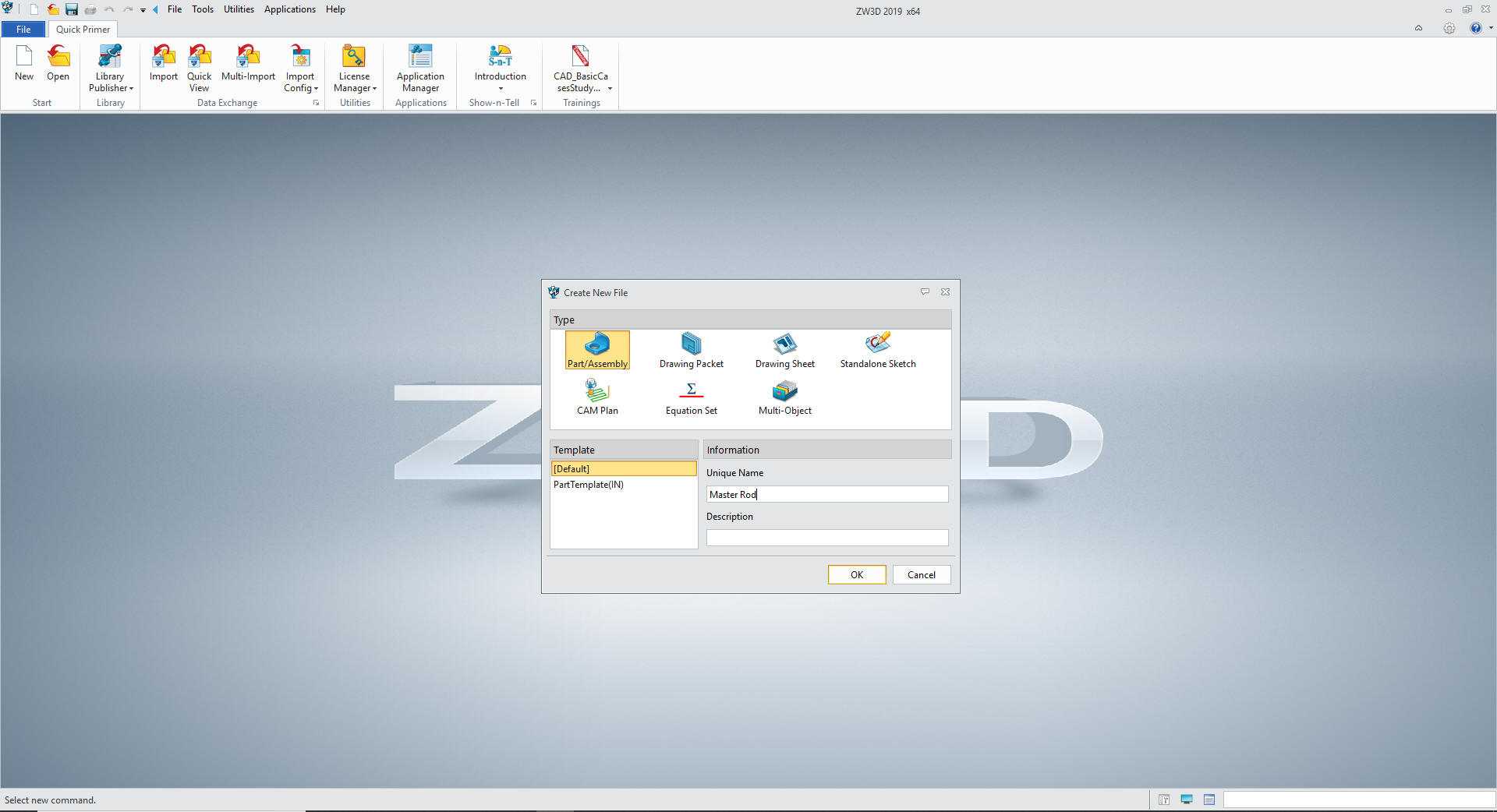
Here is ZW3D. It is set to mm so let's
get started
We open a Part/Assembly and call it MASTER ROD
These have actually turned into exercises in
modeling techniques as compared to showing a more productive CAD
systems. Again, I say there are many different ways to model a part.
I see with my exposure to direct edit modelers like CADKEY, I
rarely sketch like you see the Catia fellow doing. I have always
created my basic sketches by mostly creating offsets and trimming or
extending. It seems to be much easier. I never put in a fillet that
can be created later. What do you think?
These have actually turned into exercises in
modeling techniques as compared to showing a more productive CAD
system. Again, I say there are many different ways to model a part.
I see with my exposure to direct edit modelers like CADKEY, I
rarely sketch like you see the CATIA fellow doing. I have always
created my basic sketches by mostly creating offsets and trimming or
extending with descriptive geometry as you would to on a drafting
board. It seems to be much easier. I never put in a fillet that
can be created later. What do you think?
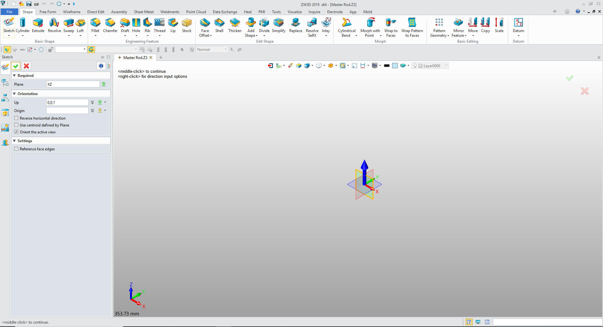
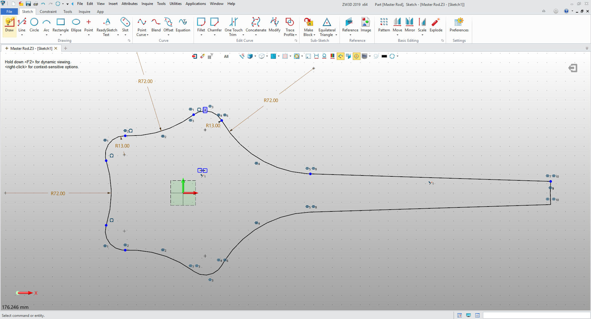
The Master Rod
We also start with a sketch on the XZ
plane.
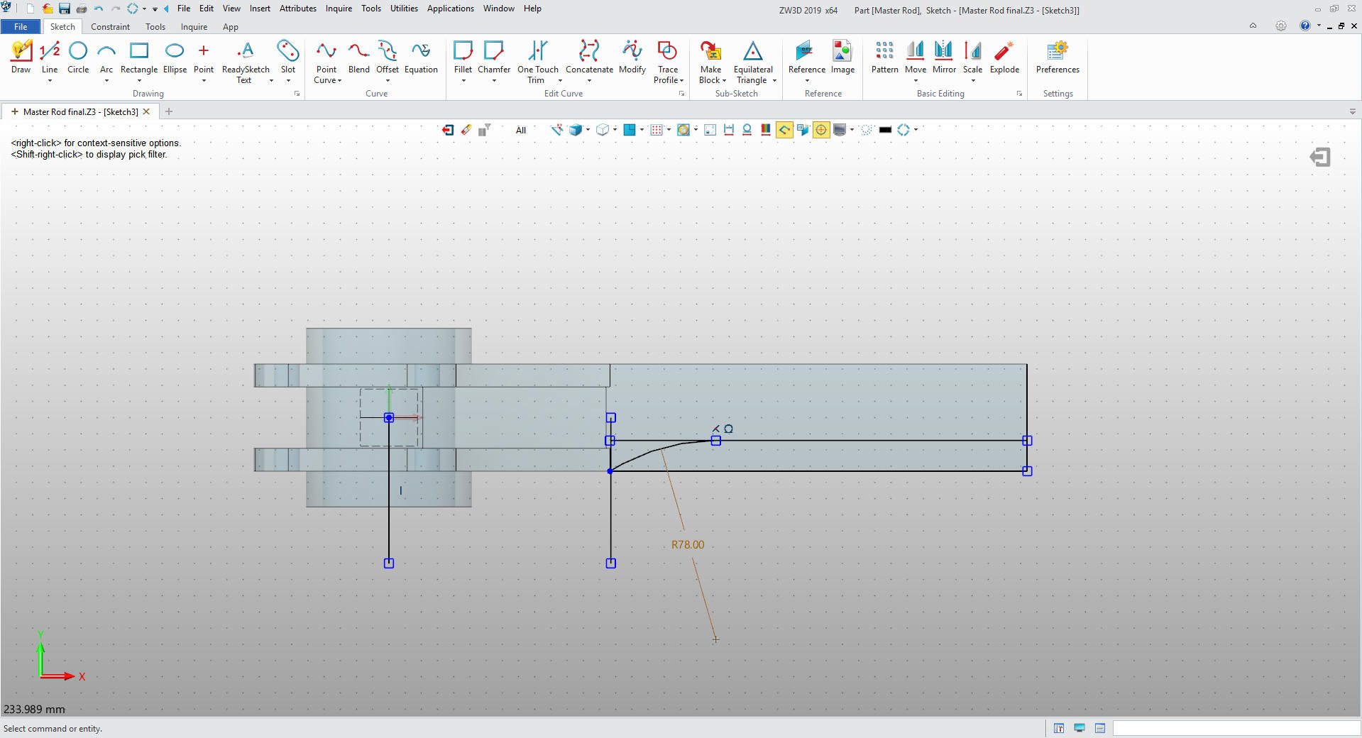
We will start
creating the sketch by using entities to set up the basic
construction for my sketch, as you can see I do no constrained
sketching. I call this StreamLined Sketching.
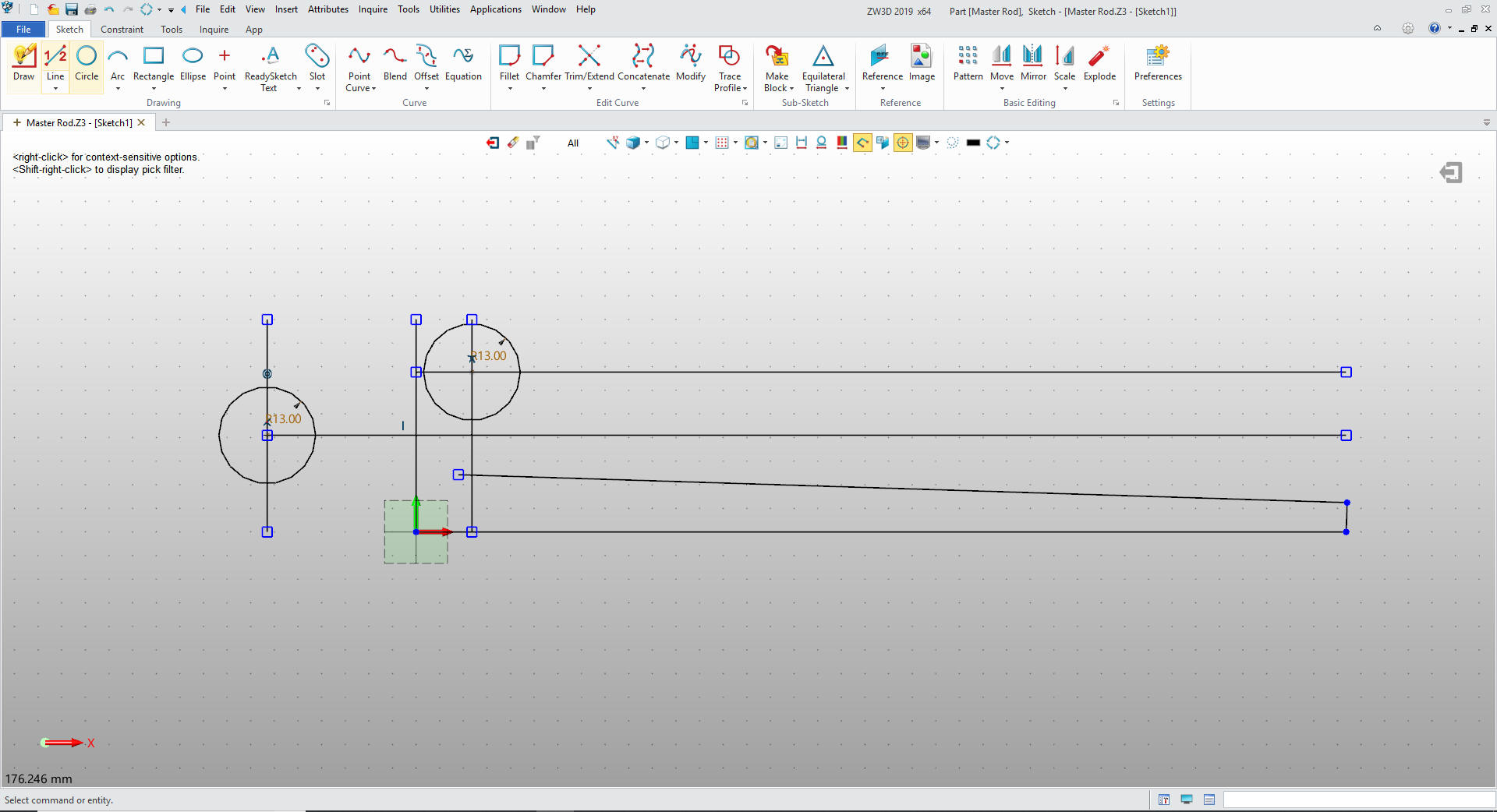
We will add
our tangent arcs.
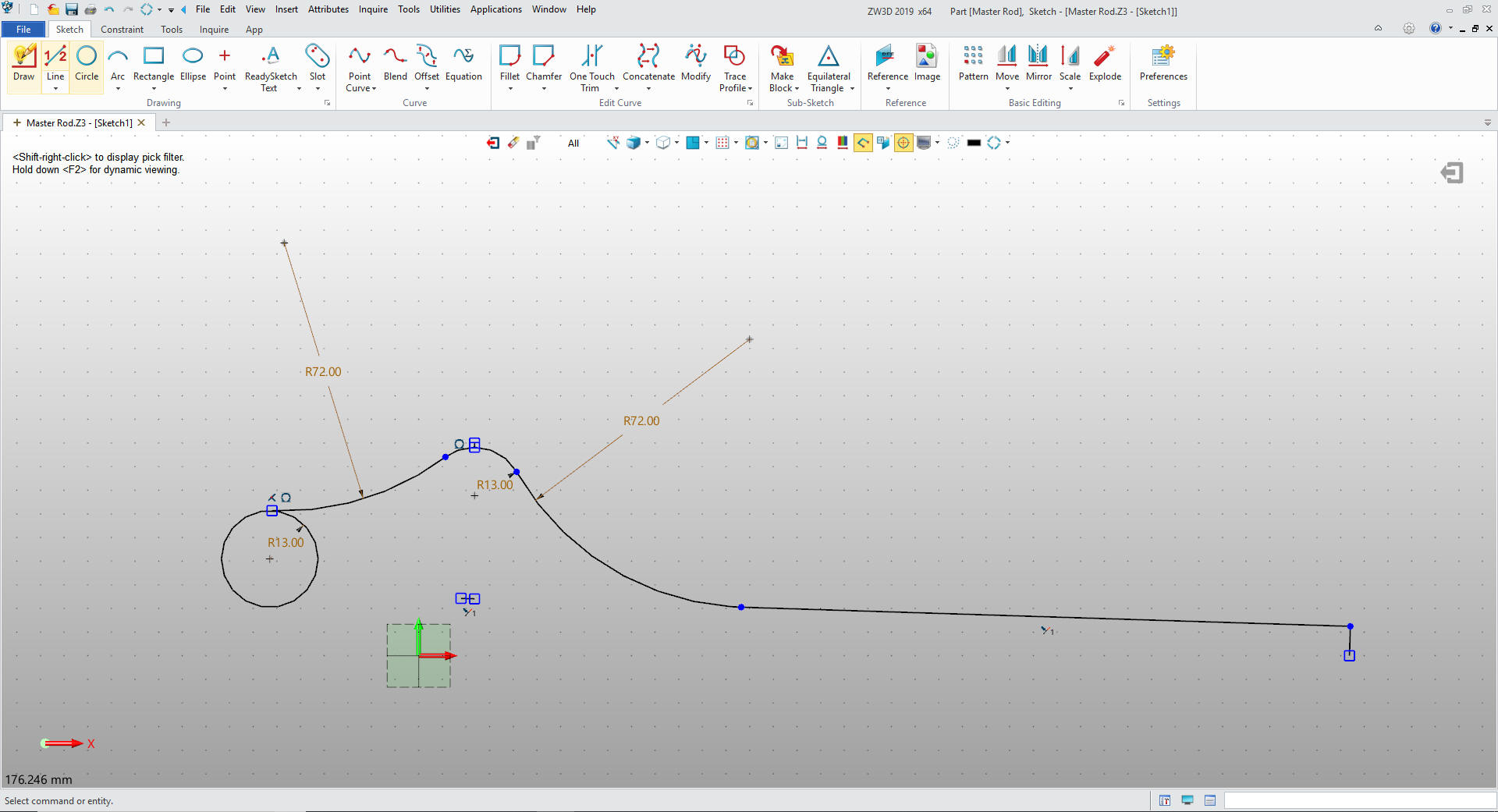
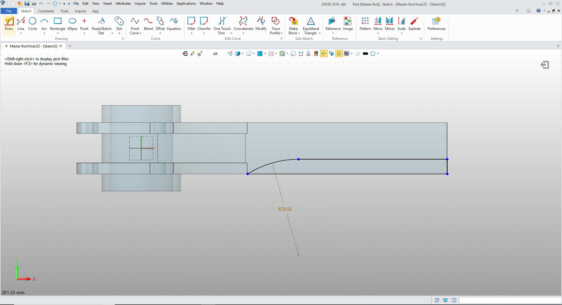
We now just trim/extend and delete the
unnecessary entities.
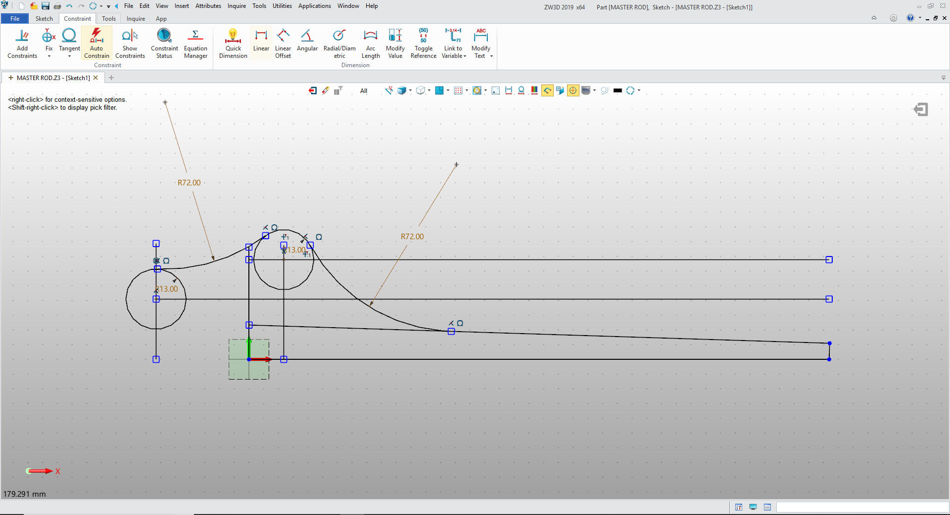
We mirror the entities and trim. If you
watch the CATIA Video the presenter stops here creates the half
solid and continues. This such a simple sketch I have no idea why.
It was more complicated to do what he did trying to be clever by
half.
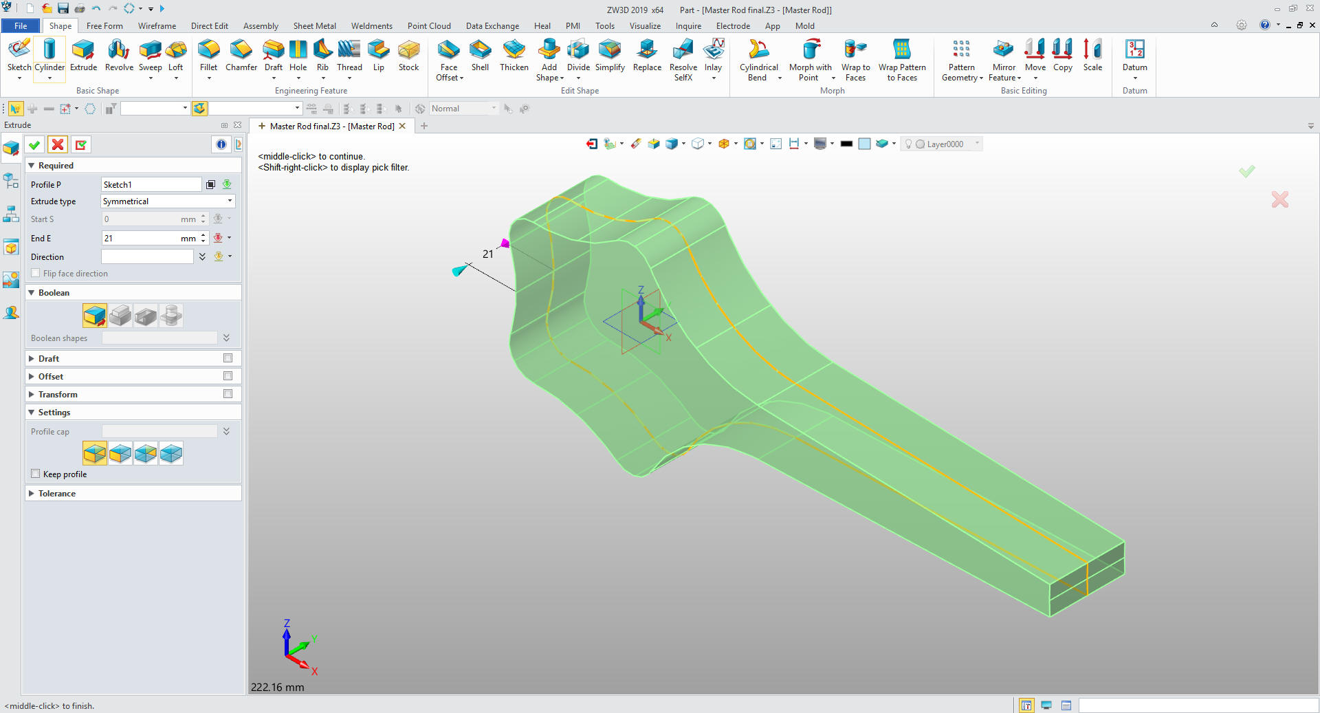
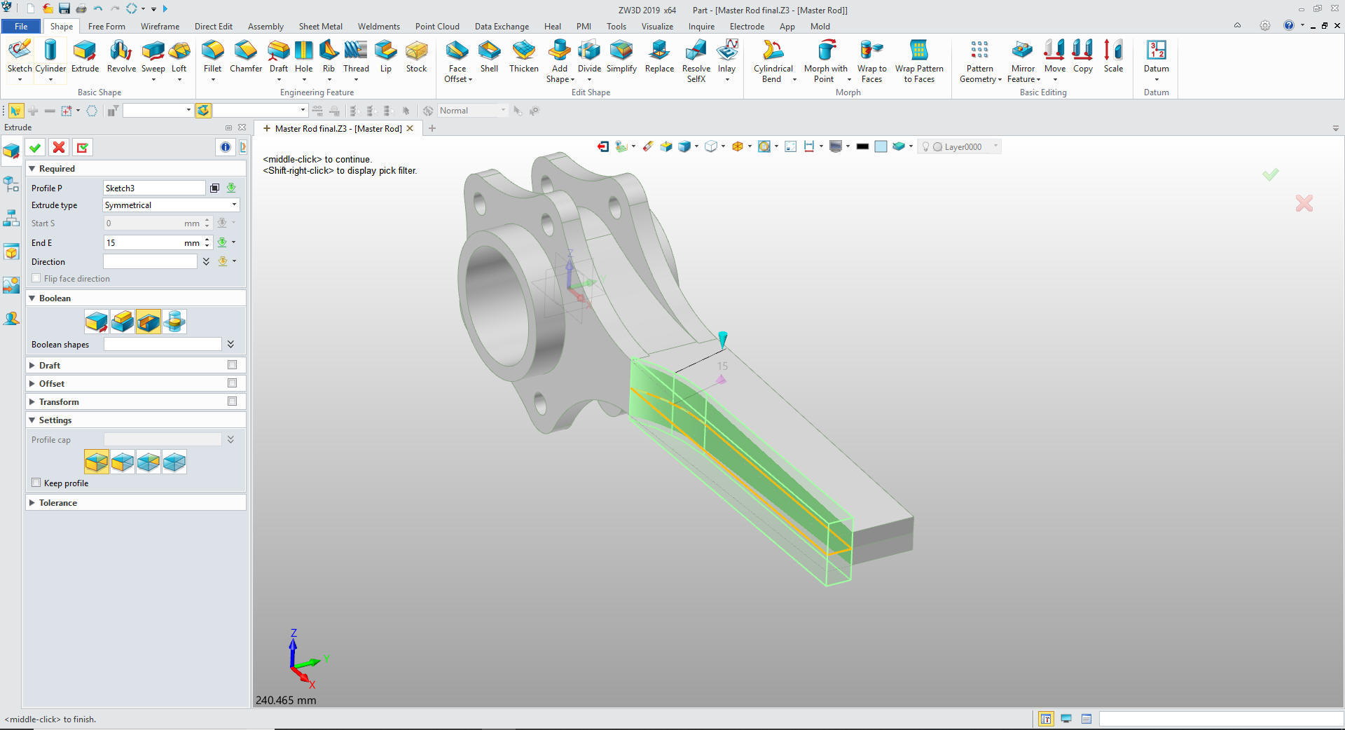
We
now will extrude mid-plane.
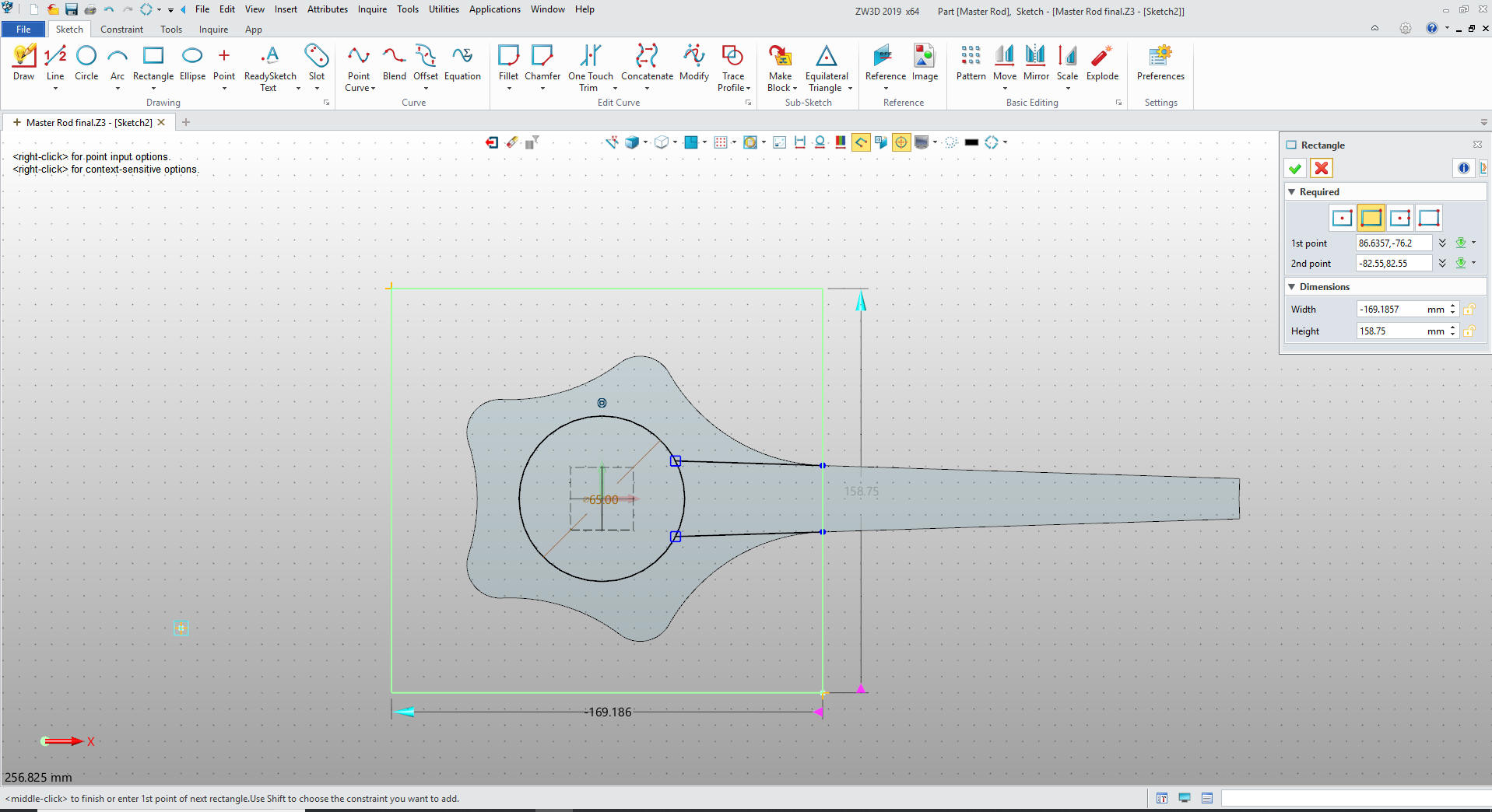
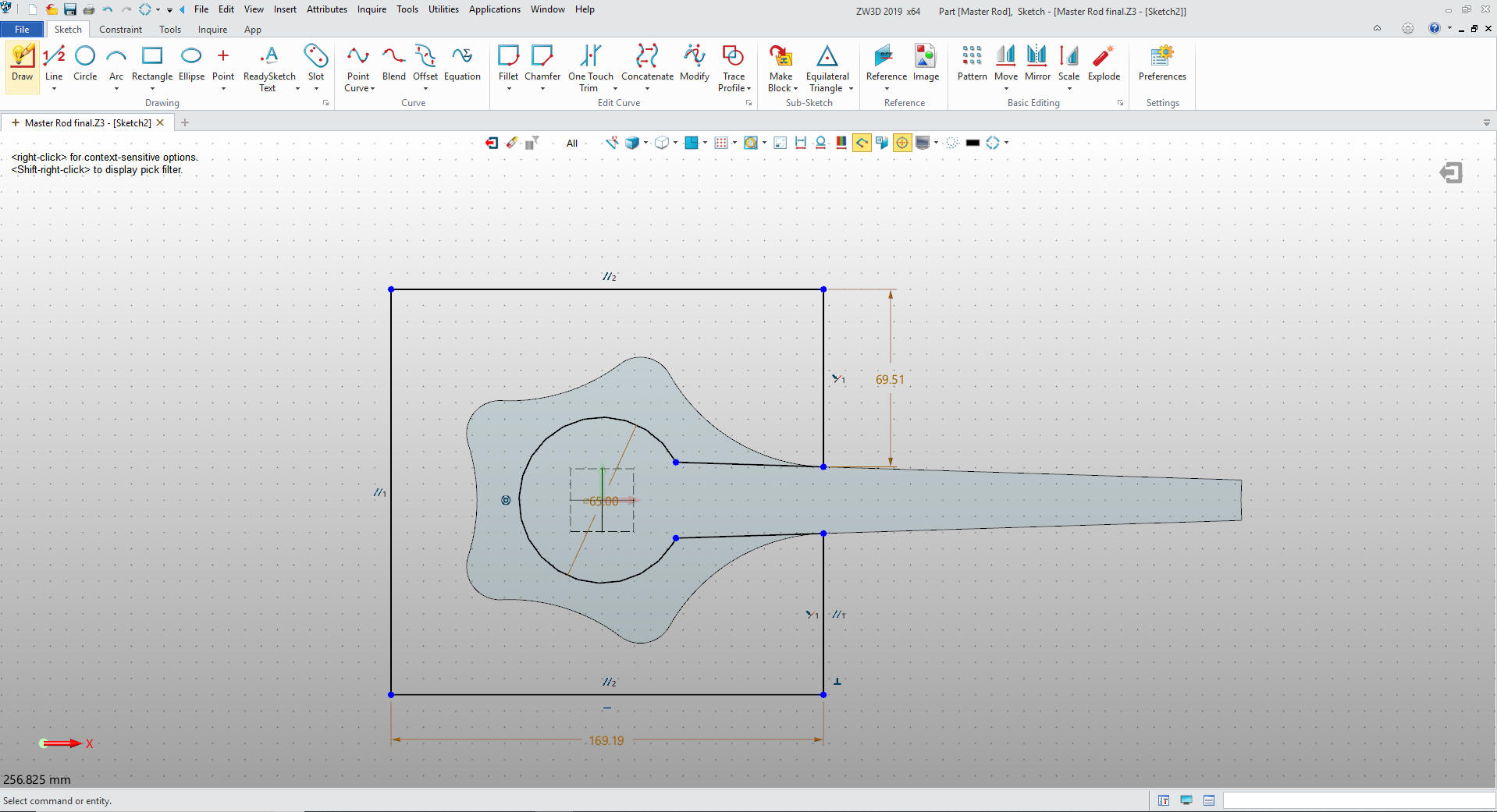
We create anther sketch at XZ plane
go to the sketch. We create the two diagonal lines by using the
existing graphics then extend to the circle and add the rectangle.
We just trim as shown and are ready to go to extrude remove.
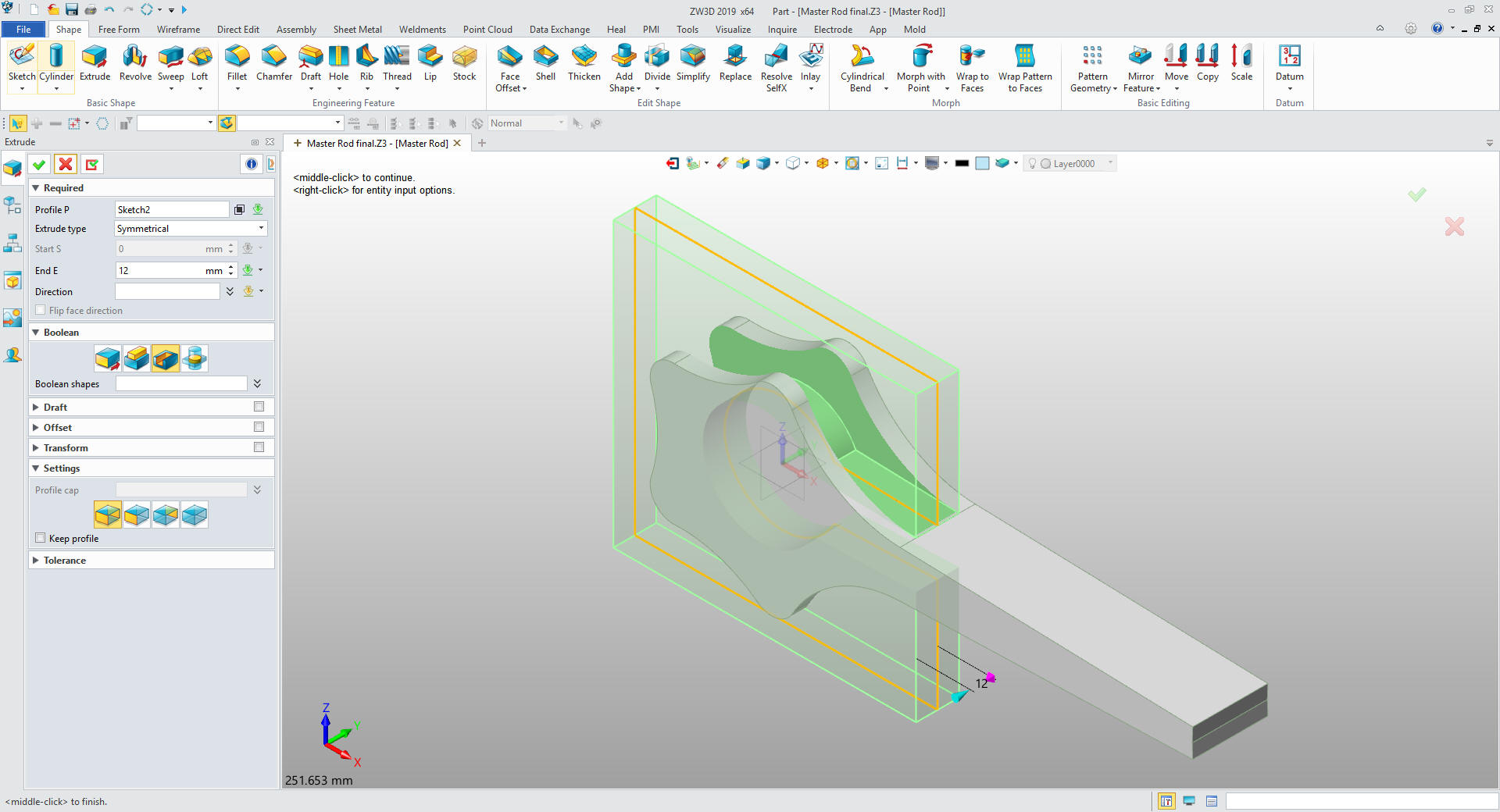
We
just extrude from mid-point and remove.
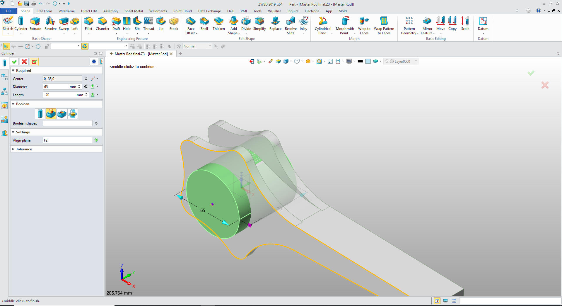
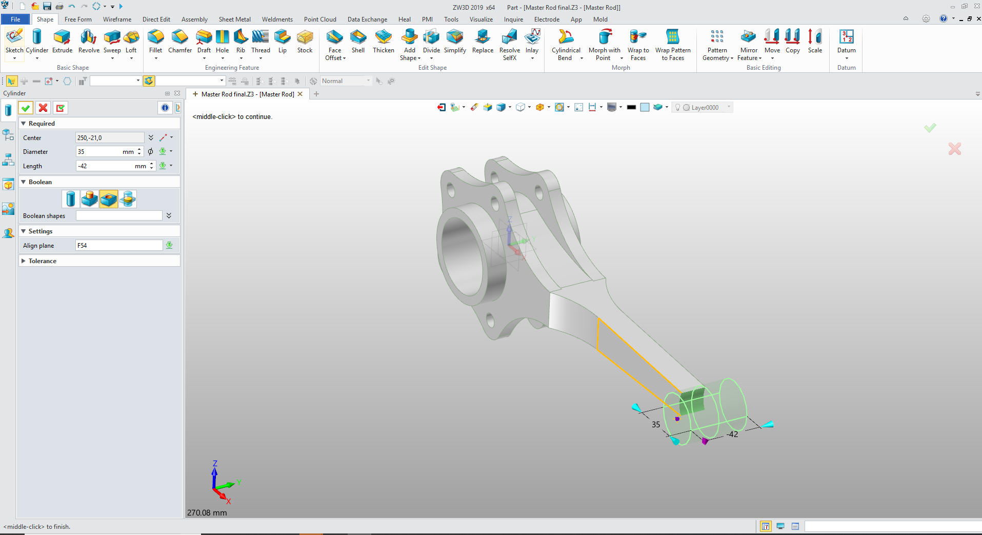
We are done with the basic shape and
just add the fillet. We can now add the boss in the middle. We
insert a primitive cylinder at X0Y0Z0 and locate and size it and set
it to add.
One of my basic rules is that you never sketch a
fillet unless the design demands it.
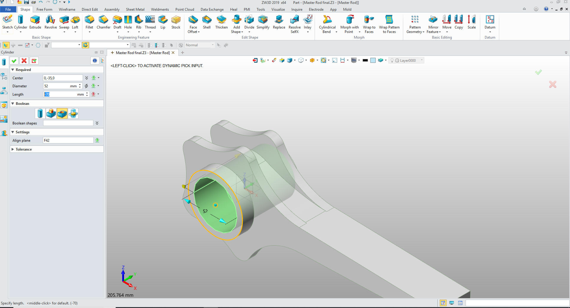
Now we do the
same thing for the hole. But this time we locate it a the center of
the block, it is already set to 70m, we just need to set it to
remove.
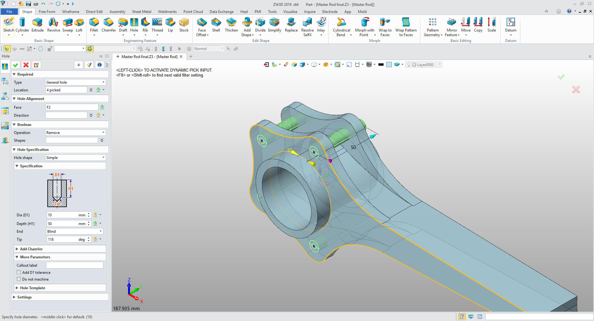
Now for the four 10m holes. We just use
the hole feature and select the center of the tabs. Mirroring seems
like a silly process for such few entities. Doing the complete part
gives a better control of the design.
Now create sketch on the XY plane and go to the plane. We create
a vertical line at X0Y0Z0, create an offset line create the arc.
We do our trim and when there are blue dot we know the sketch is
ready. Nope, not one constraint.
We
exit the sketch and extrude the shape.
We
mirror the feature and add the boss at the end by inserting a
primitive cylinder locating and sizing it.
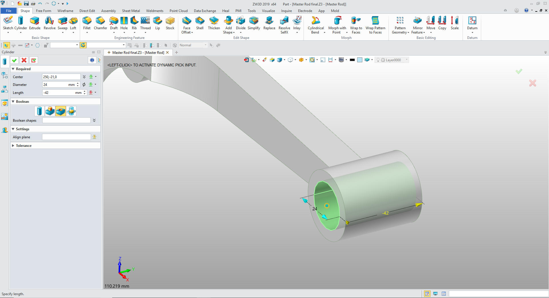
We
insert another primitive cylinder in the center of the new cylinder
size and set to remove.
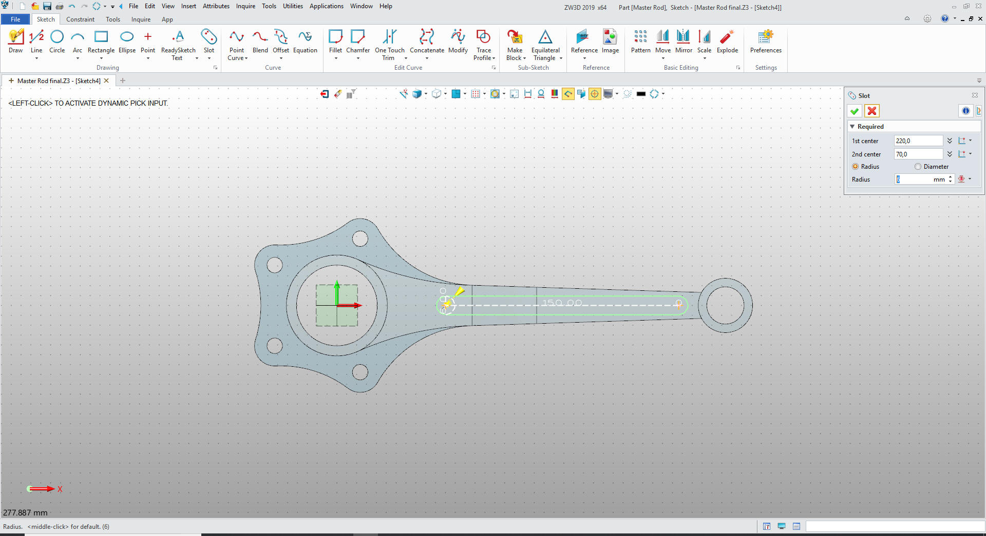
Now
we just have the slot left. We create a sketch the outside face and
activate it.
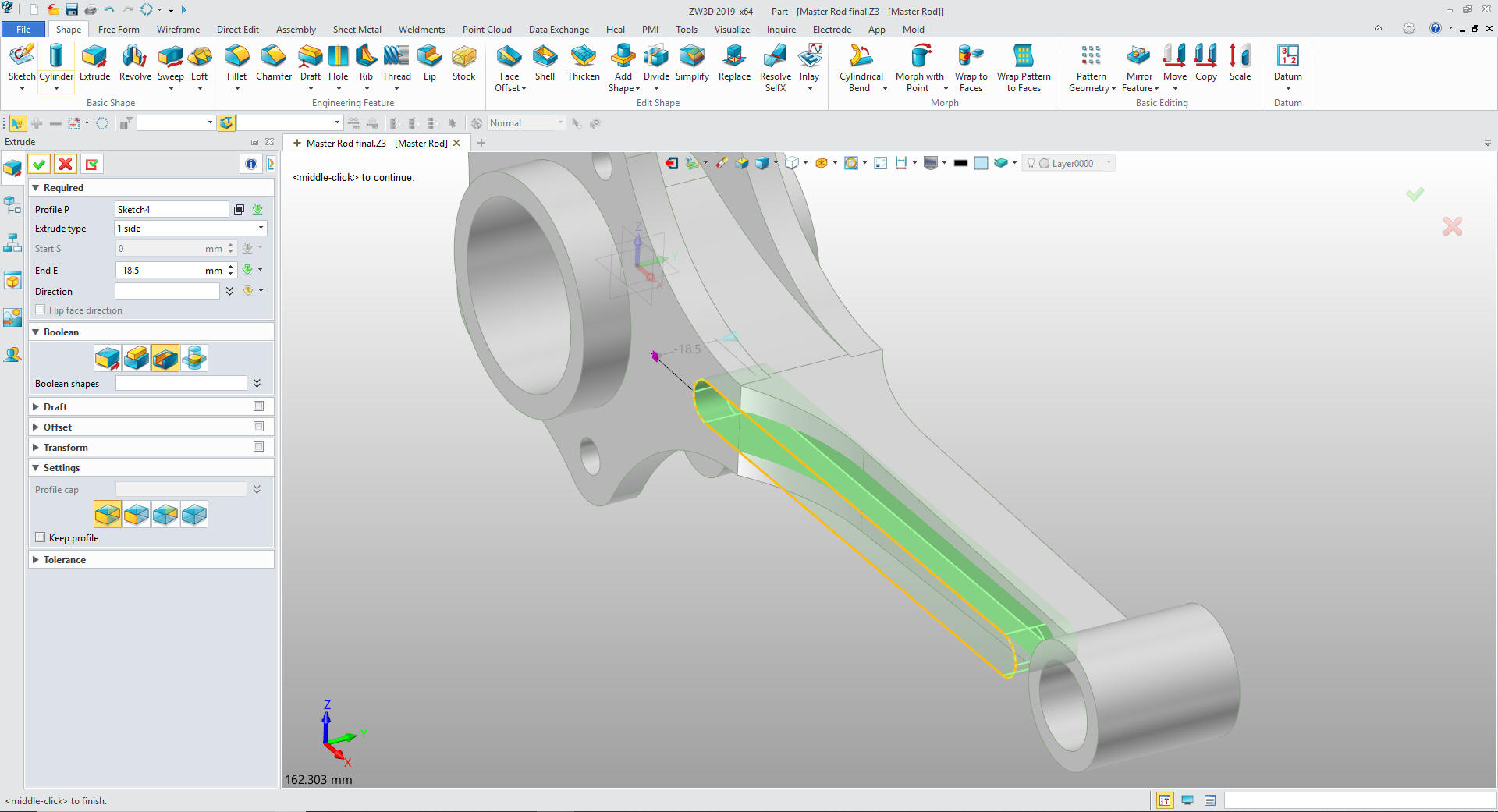
We exit the
sketch and extrude the slot.
We mirror the slot and add the
fillets and we are done. I can't imagine hundreds of Boeing, Airbus,
Gulfstream and Bombardier designers struggling with CATIA and
constrained sketching only. I can tell you moving to StreamLined
Sketching and Feature Base modeling would increase productivity 5X
with conceptual design and 10X with changes. The only constant in
engineering is change.
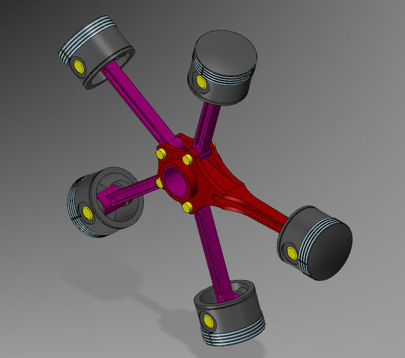
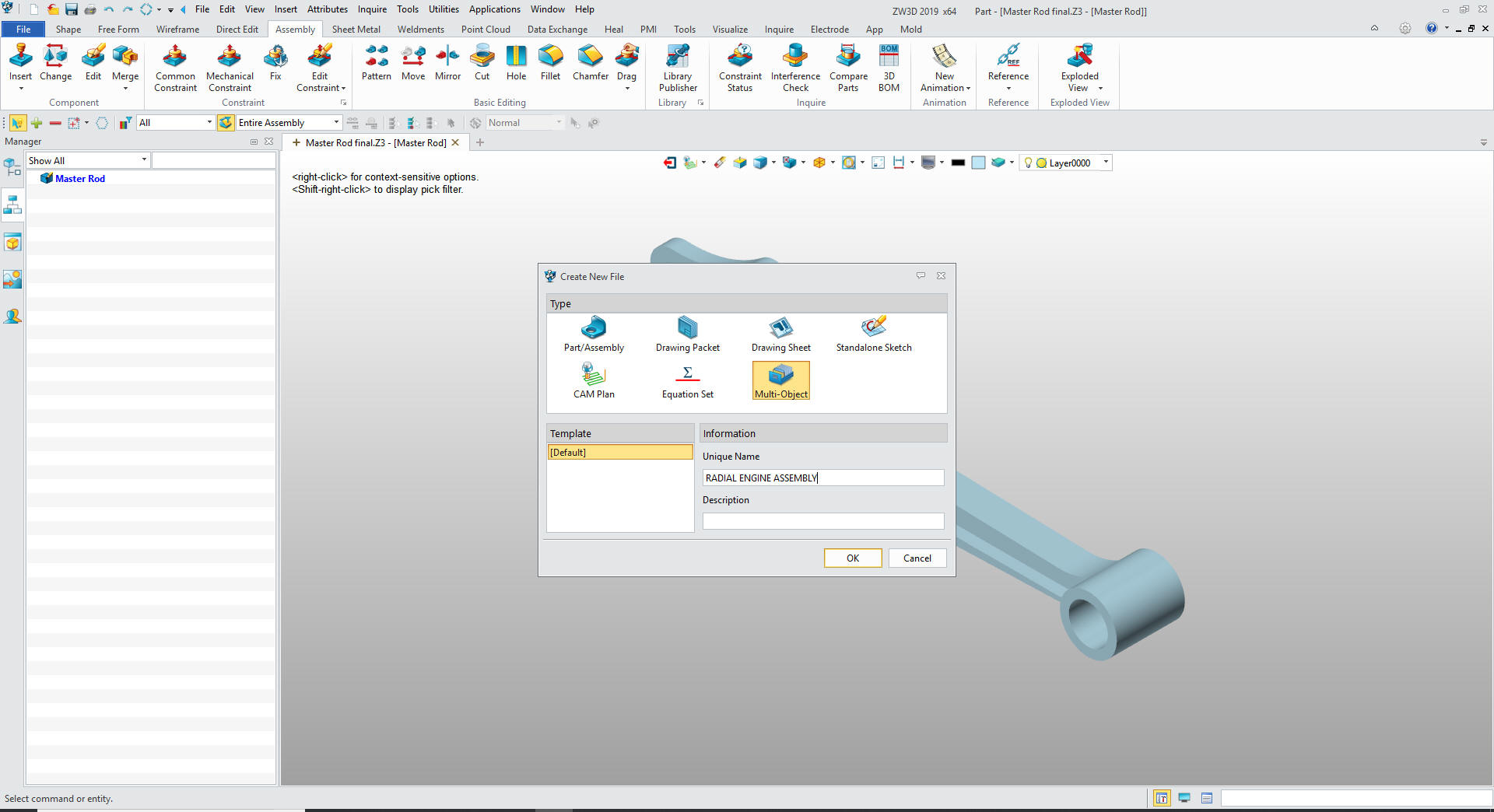
RADIAL ENGINE ASSEMBLY
We create a new Multi-Object file and name it "RADIAL ENGINE
ASSEMBLY"
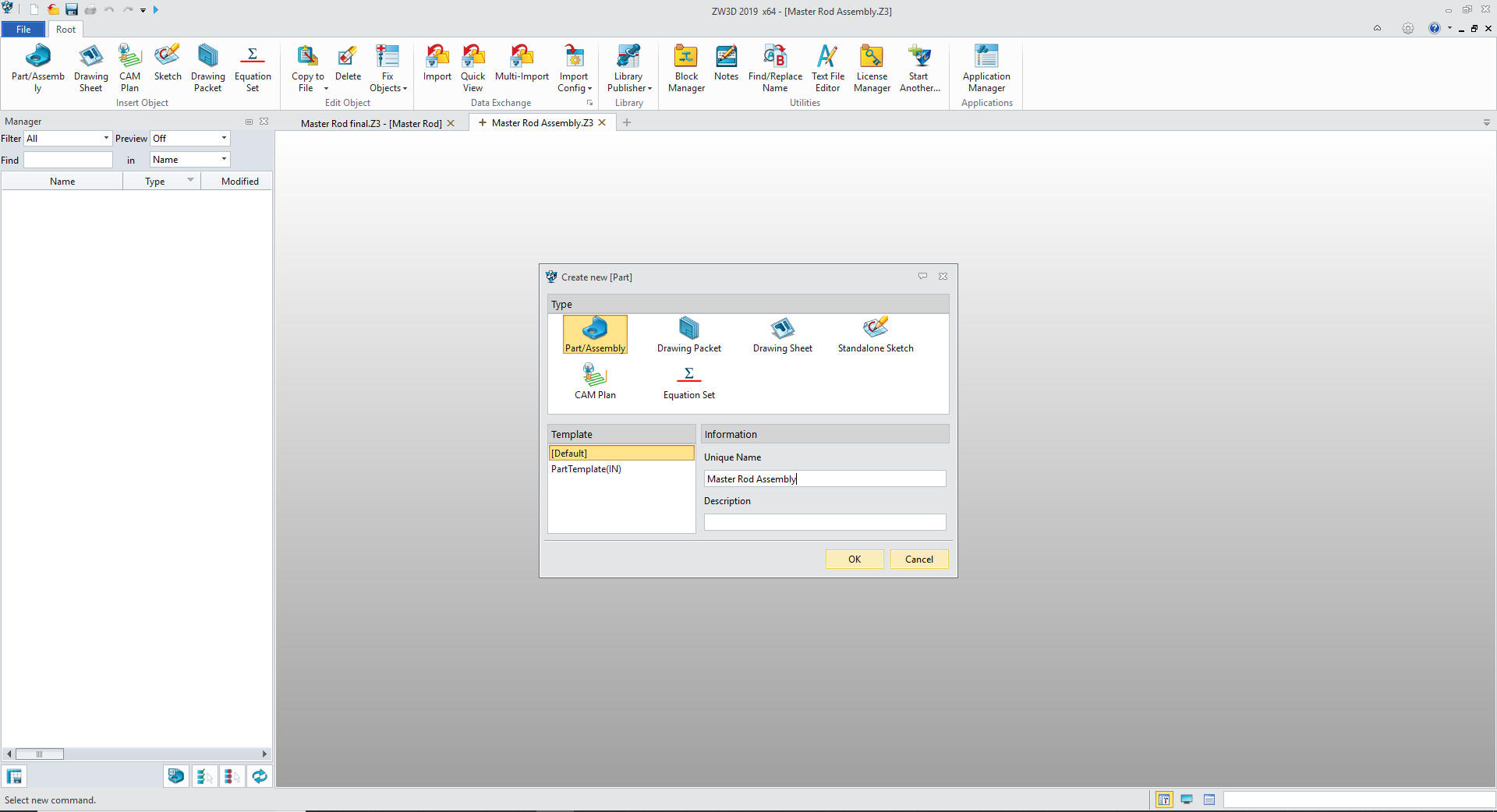
We
create the top assembly Radial Engine Assembly
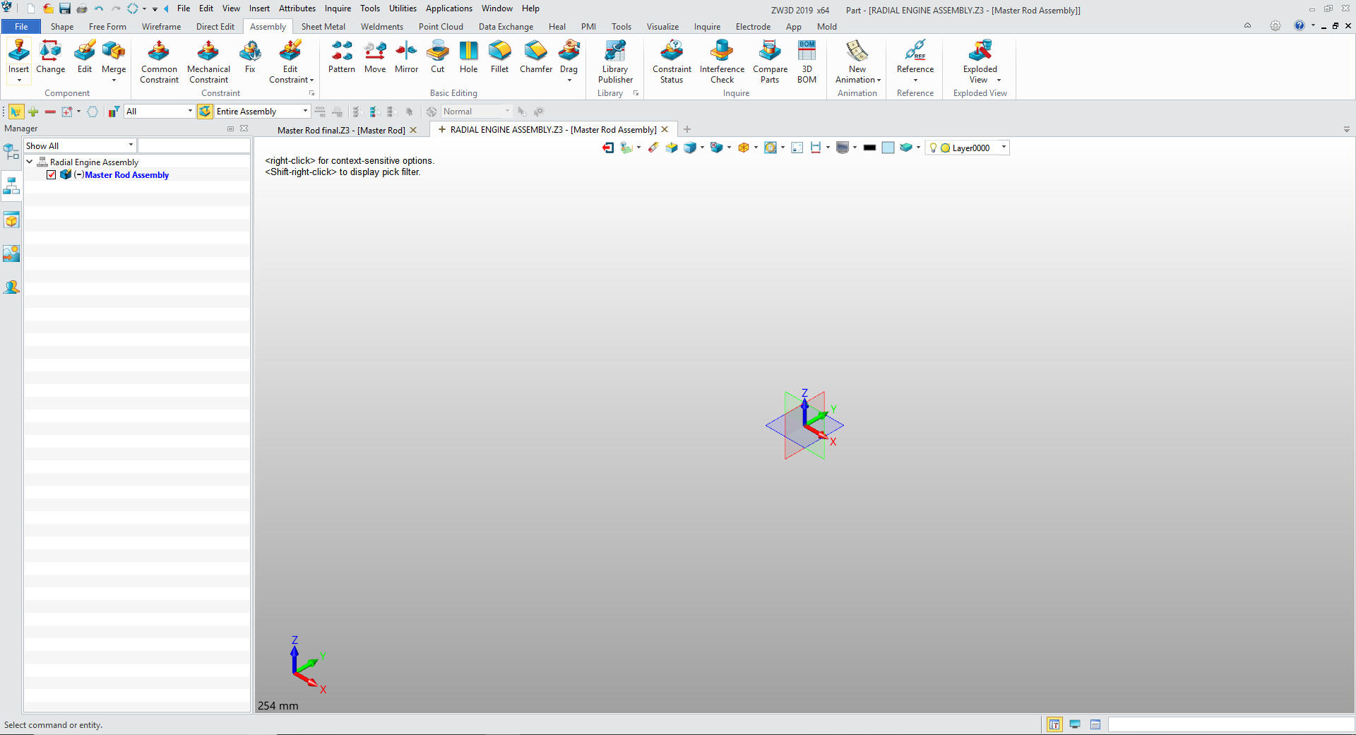
We
will insert our first component which will be the already created Master Rod
Assembly.
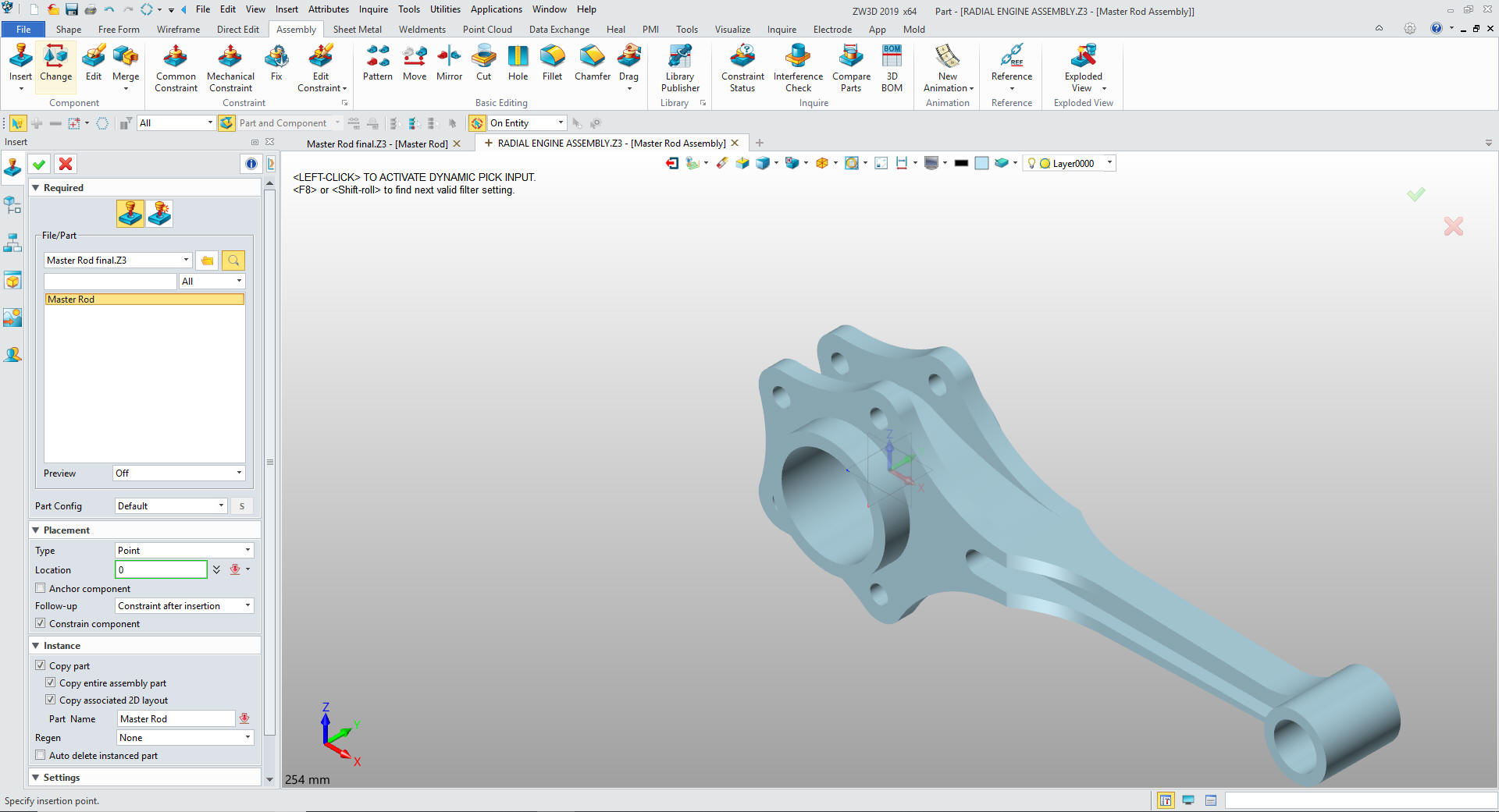
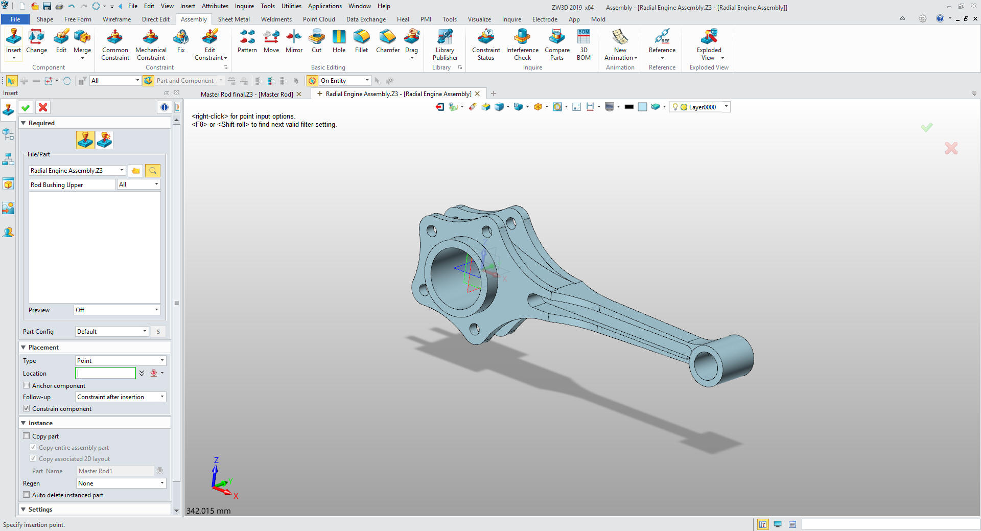
We
already have the Master Rod open we just insert it and set to copy
to not have it associated to the original file and accept the
default X0Y0Z0 location. This will be a detailed assembly and be the
authority for the Master Rod. You can operate ZW3D just like any of the
major Solidworks clones with reference parts if you chose.
We have Four assemblies.
We can
set up the assemblies by inserting all of the parts or we can do
them as we model them. We are doing top down/in-context design so we
will do the parts inside the assembly. You can easily move parts and
sub-assemblies.
We now insert the
Piston Assembly under our Master Rod Assembly
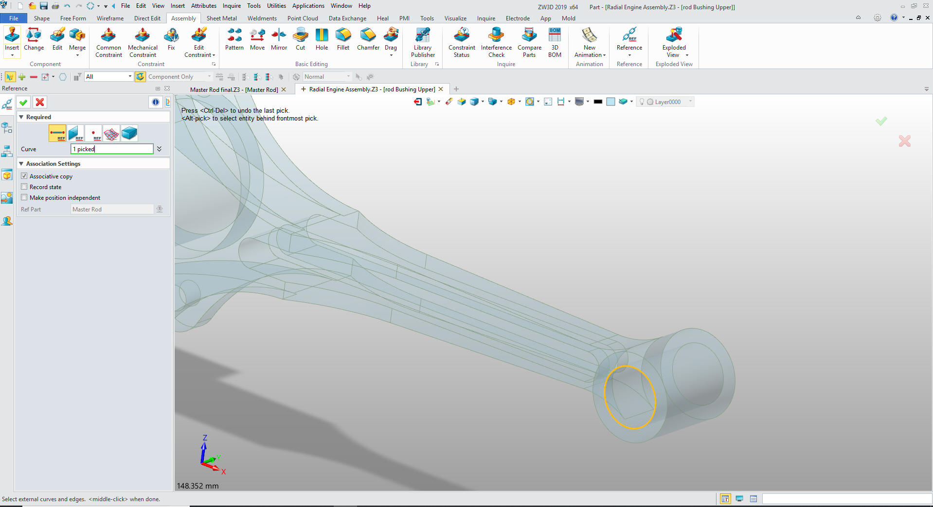
Bushing
Rod Upper We we now create the Rod Bushing
Upper by inserting a component under the Piston Assembly.
We go
to the assembly mode and create a reference circle as shown.
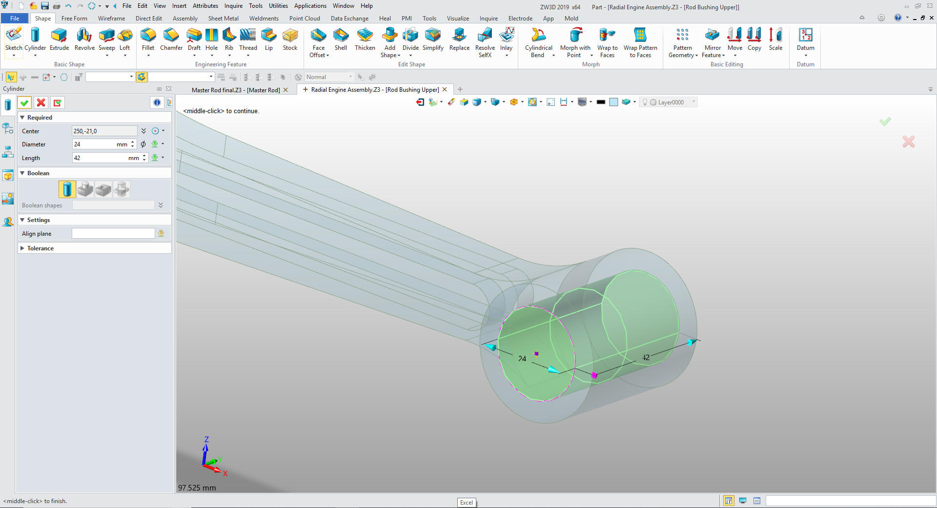
We insert a primitive cylinder at the
center of the the reference circle.
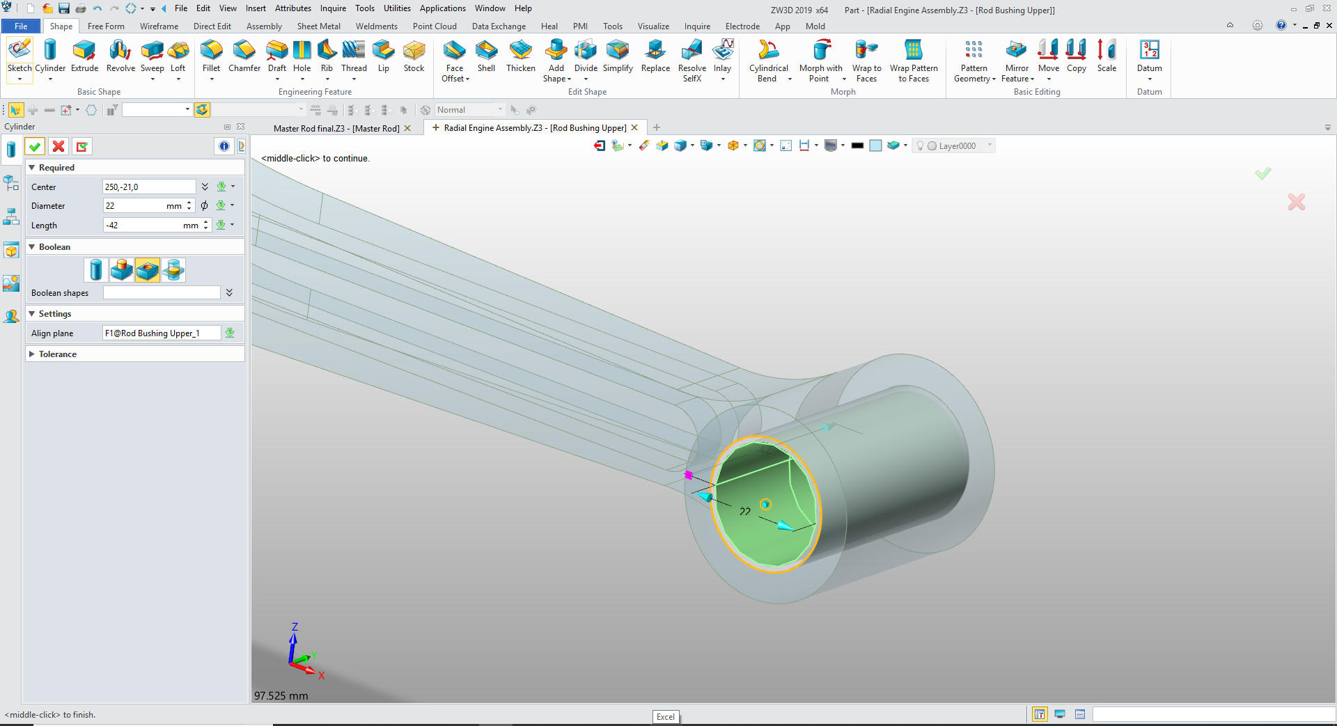
We
insert another primitive cylinder center it on the existing cylinder
and size it and set it to remove.
We are
done with the Rod Bushing upper now for the Piston Pin. We change
the color of the bushing and hide the reference circle. We now add
the Piston Pin as
another component under Master Rod Assembly.
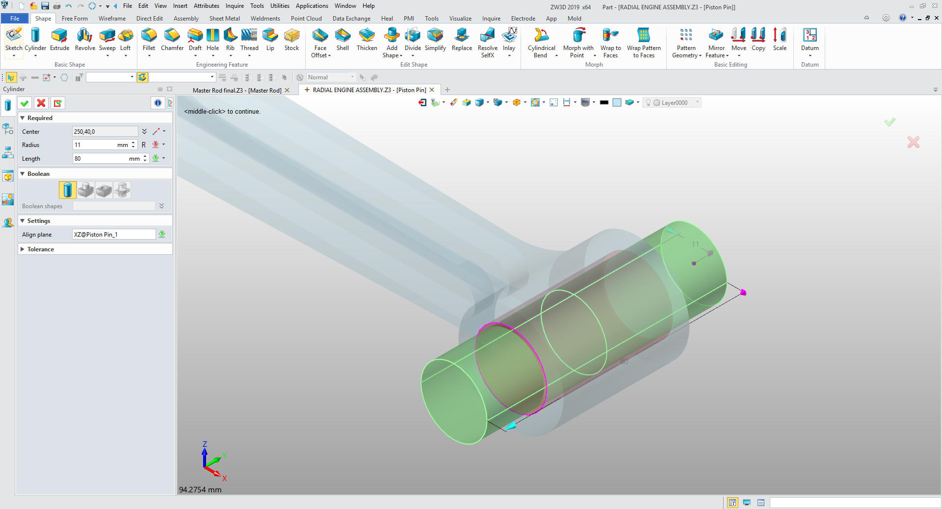
PISTON PIN
Again we go to assembly and create a reference curve. We insert a
primitive cylinder at the center of the curve and size it.
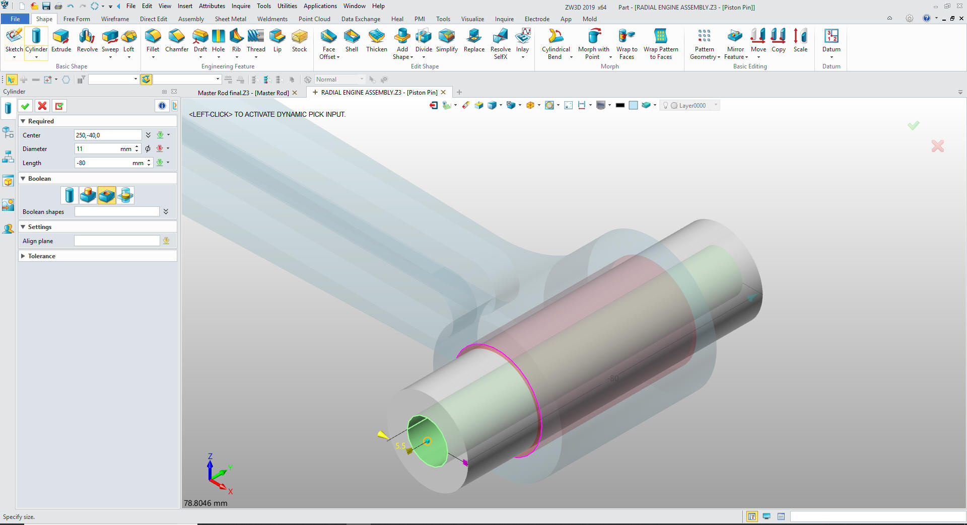
We
insert another primitive cylinder at the center of the pin and size
it.
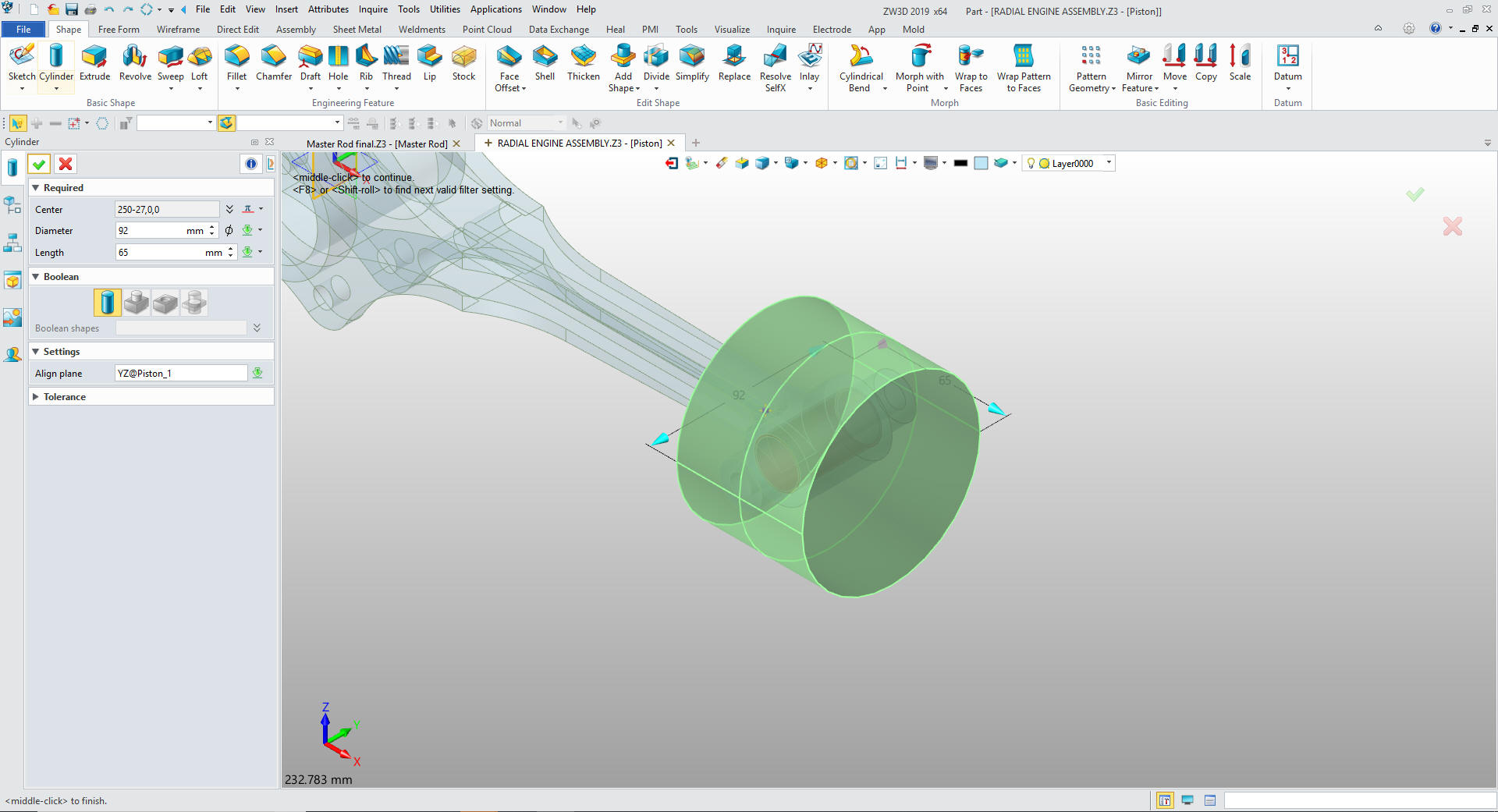
We are done with the pin, we will change the color and blank the
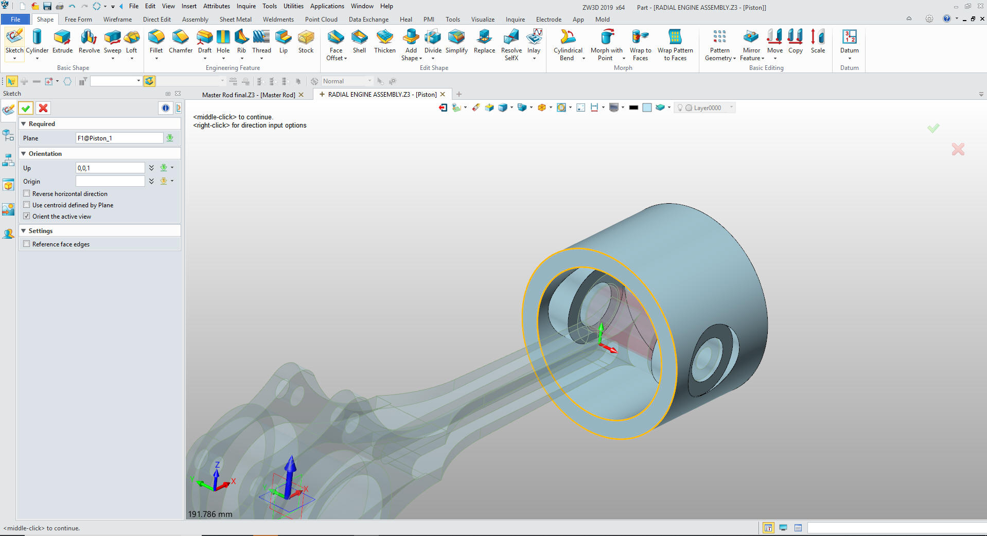
reference circle and insert the component Piston.
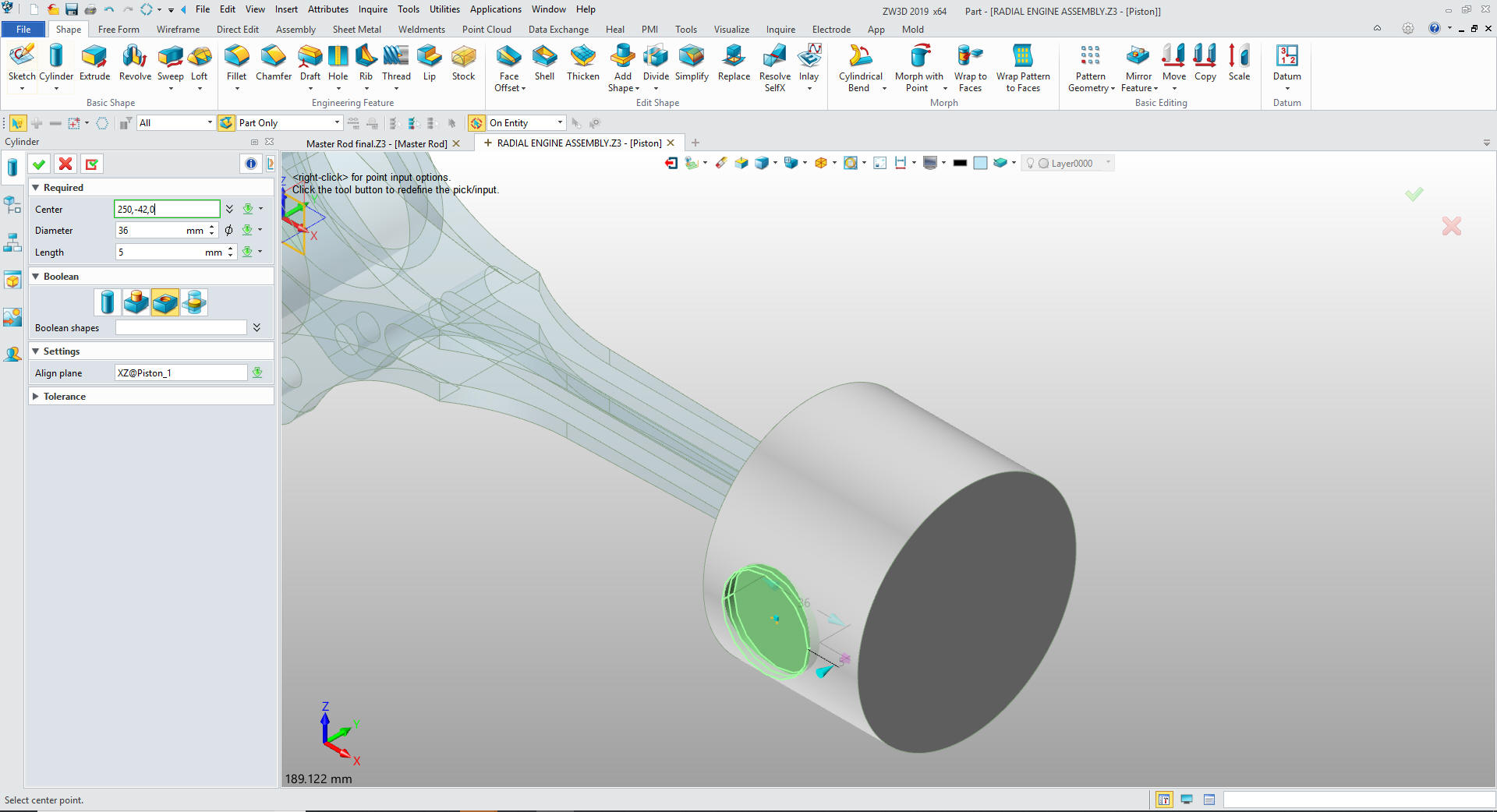
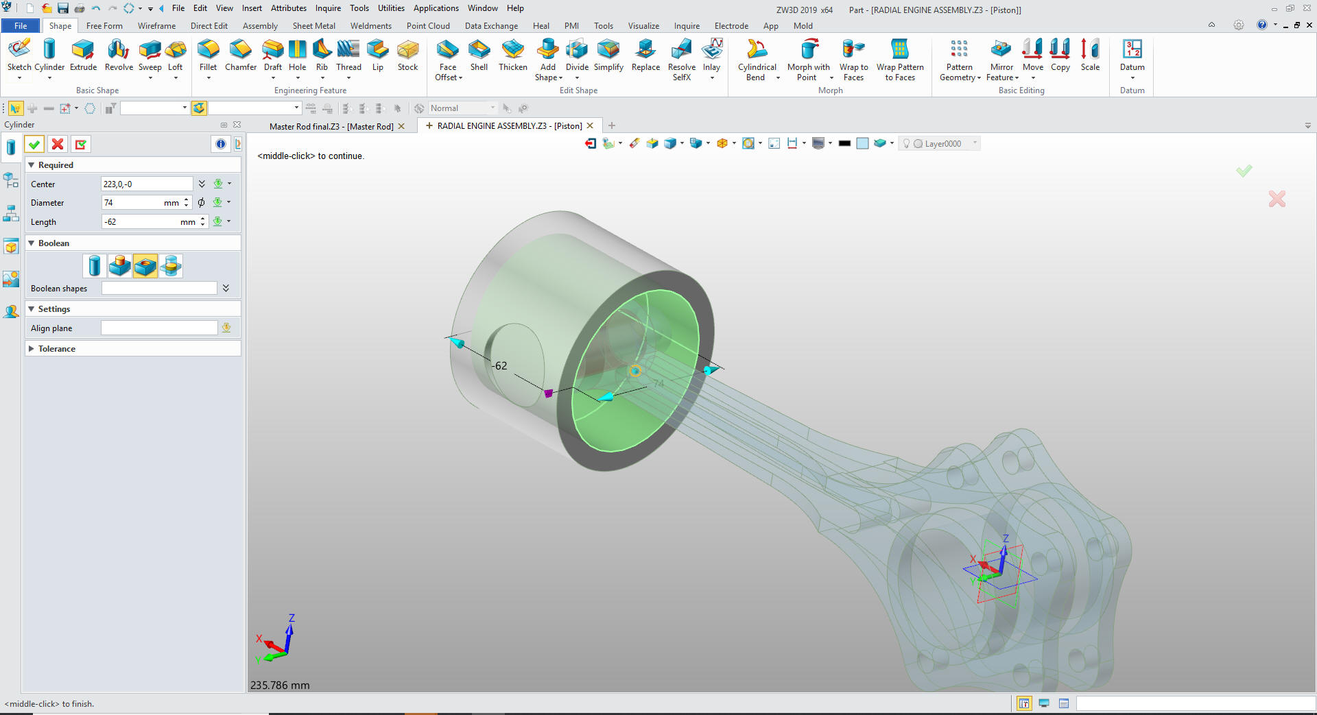
We insert another primitive cylinder on the XZ plane, locate it,
size it and set it to remove. You get very adept at locating these
primitive shapes. It is actually quite fun!
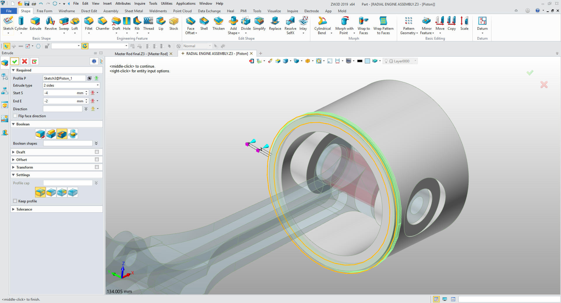
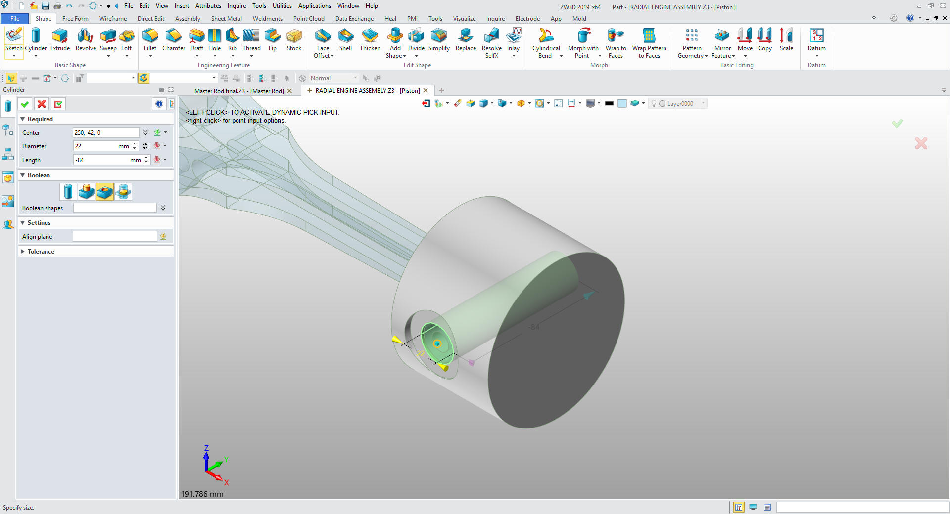
We
will mirror the feature and insert another primitive cylinder on the
bottom of the base cylinder, size and set to remove.
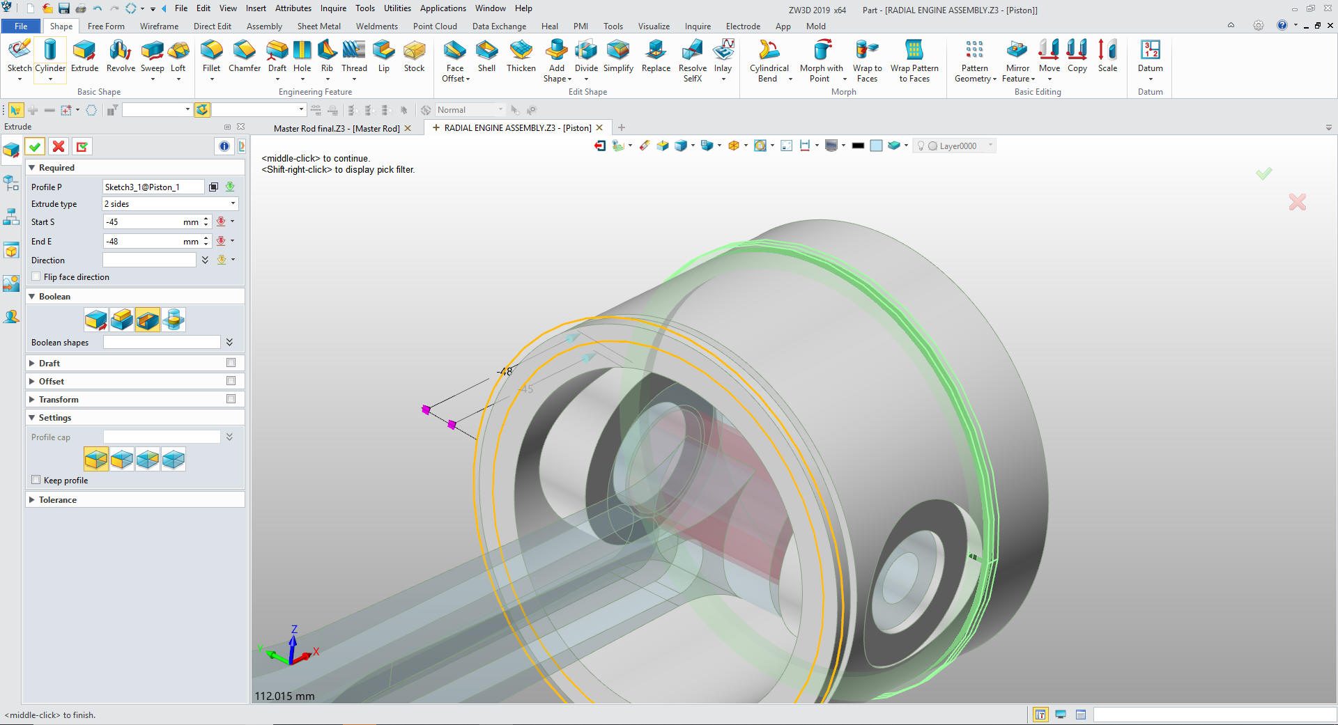
Now
to add the inside boss. We insert a primitive cylinder and locate,
size and set to add.
We
mirror the feature on the XZ plane.
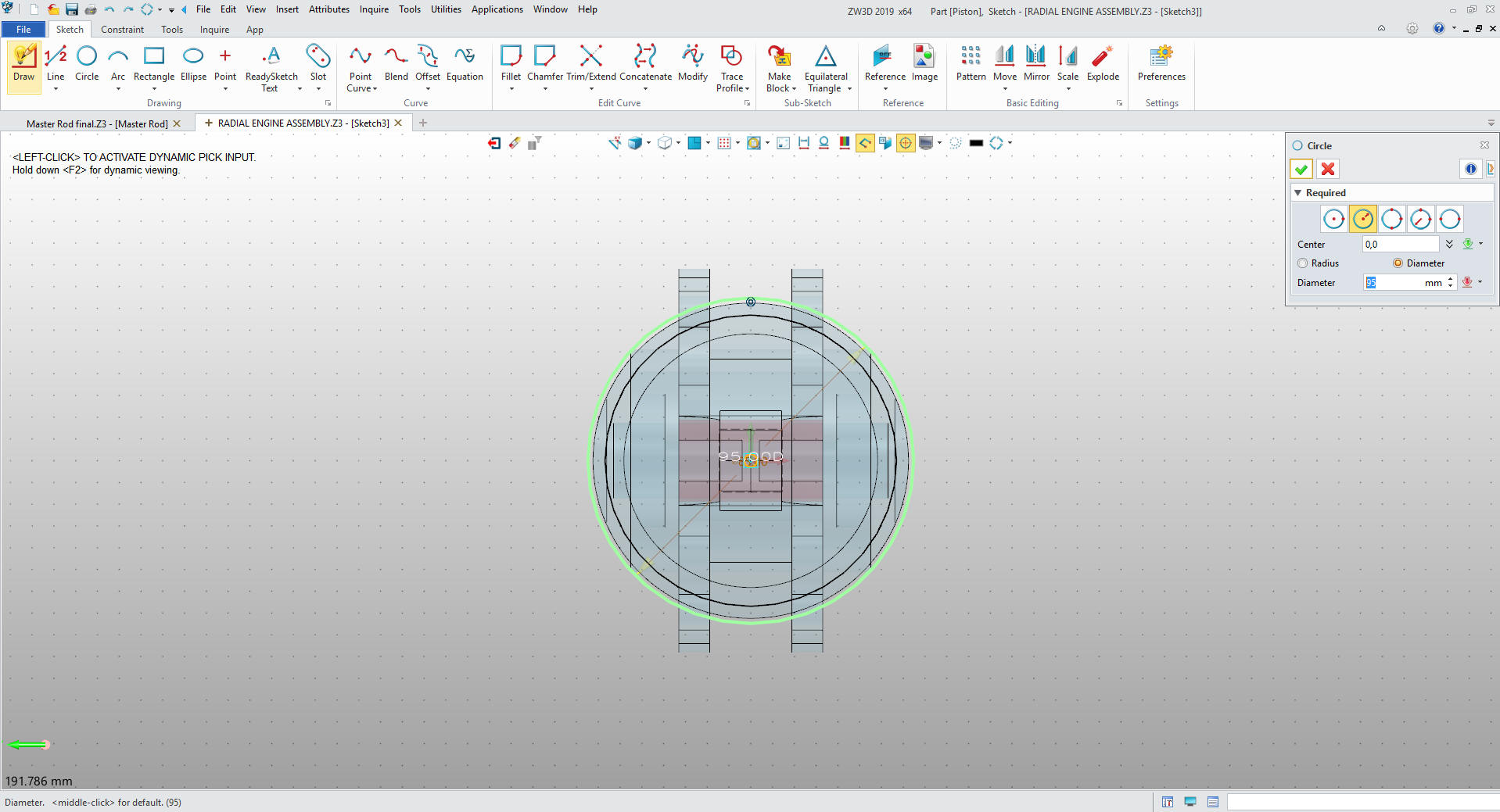
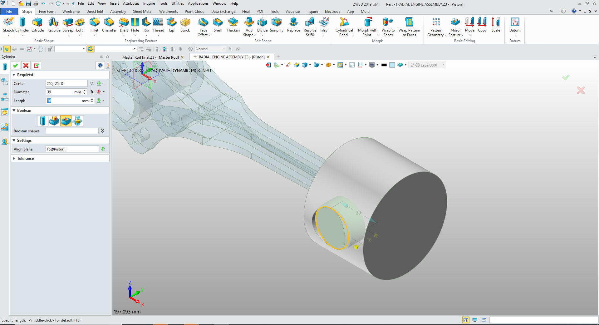
Now
for the piston pin hole. Insert a primitive cylinder at the center
of the face and size it.
We We now
create the bottom groove.
We create a sketch on the bottom
of the piston.
Create the sketch.
We
select extrude the sketch by locating and setting the width.
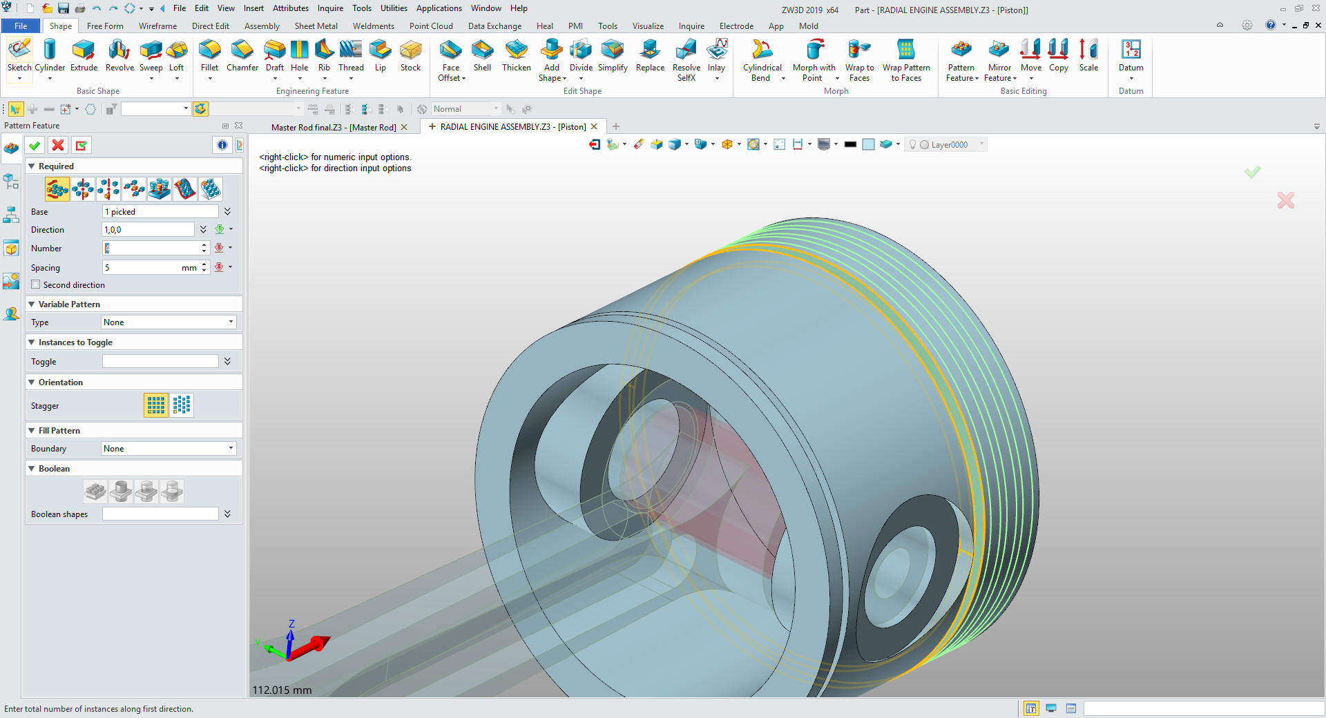
Now
for the piston grooves. We copy the previous sketch and create the
bottom ring groove.
Now
we pattern the existing groove.
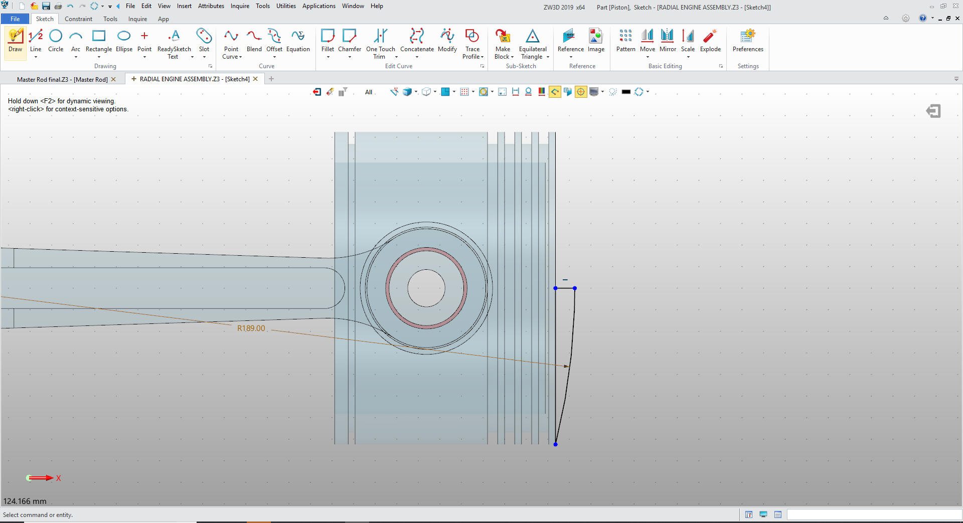
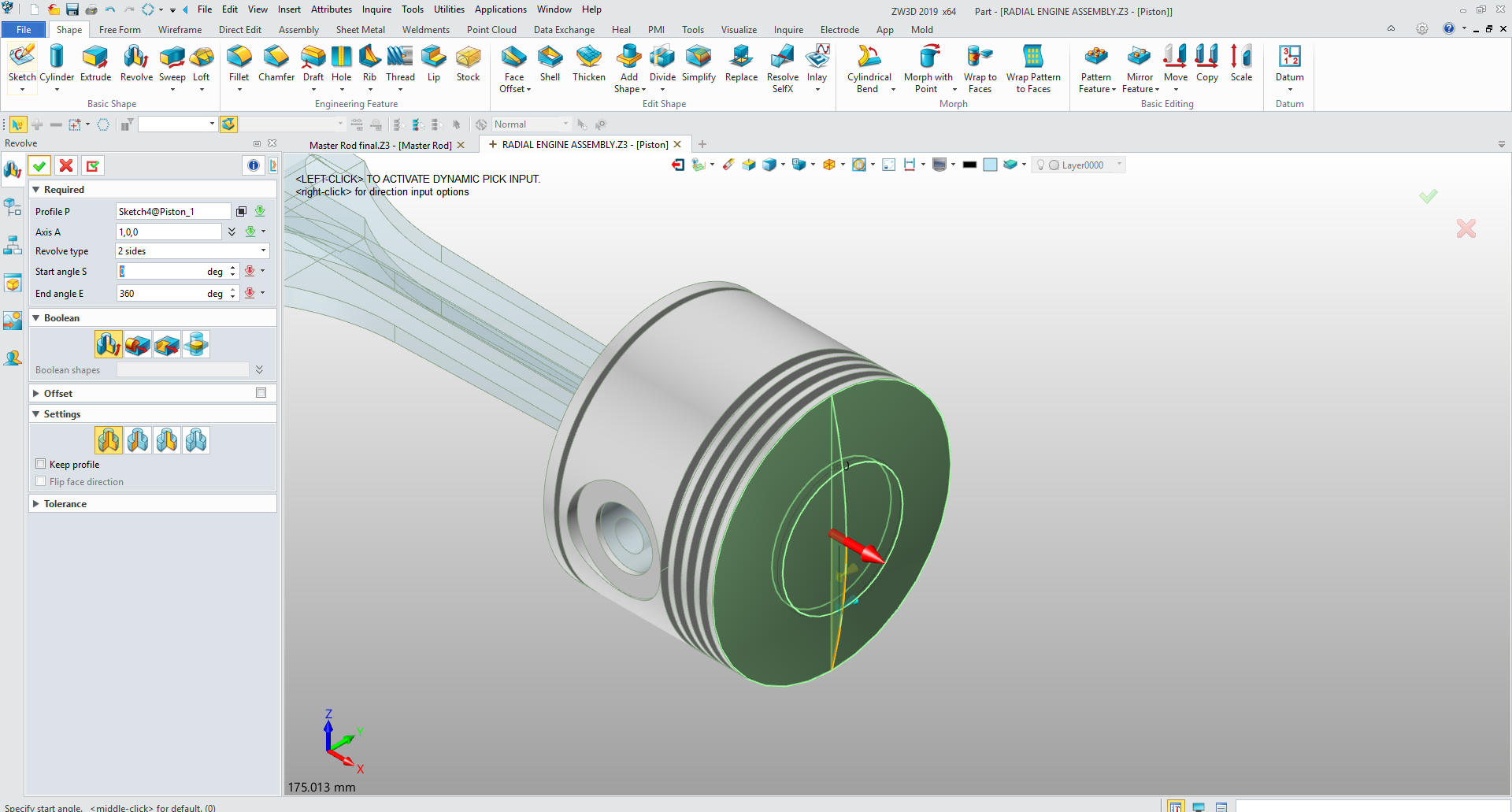
We
create a sketch on XZ plane to create the top of the piston.
We
select revolve and select the sketch set the axis and set to 360.
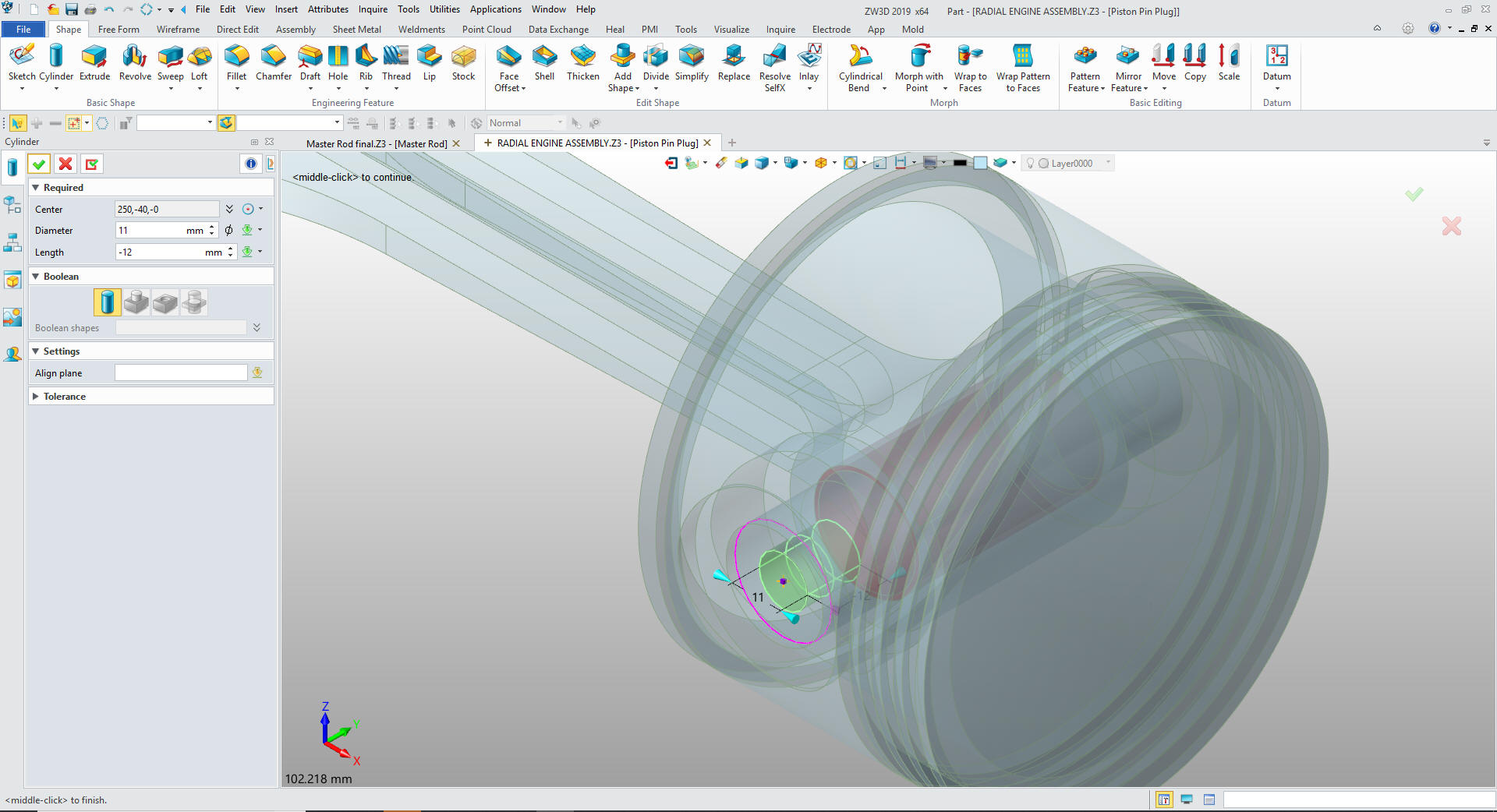
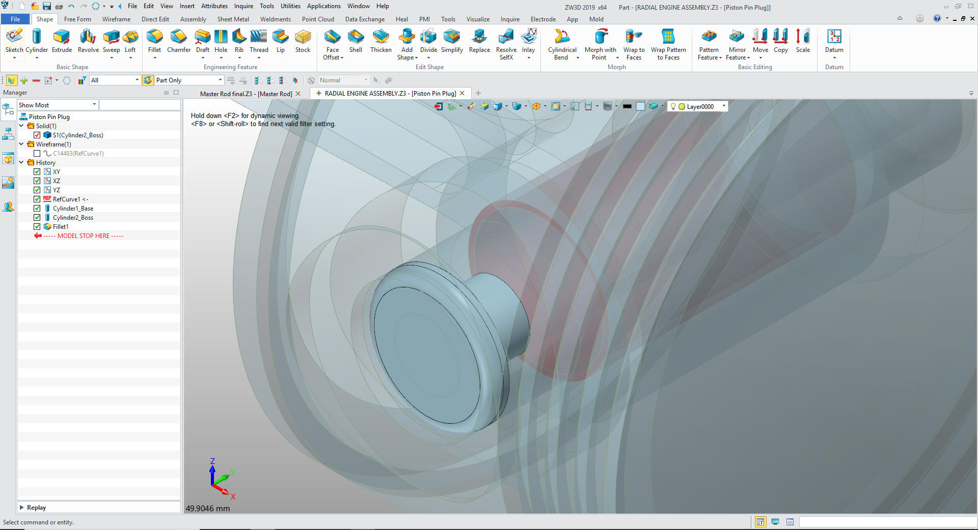
That completes the piston. We will now create the piston pin plug.
We go to the assembly mode and create a reference on a mating edge.
We insert a primitive cylinder on the circle and size it.
Now
for the top of the plug. We insert a primitive cylinder on the
existing cylinder size it and add the fillet. It is important to
know which feature you use for a reference. We hide the reference
circle.
We
now have to copy the piston pin plug. We rotate it 180 degrees and
we are done with the piston assembly.
We now create the
Piston/Articulate Rod Assembly under the radial engine assembly and
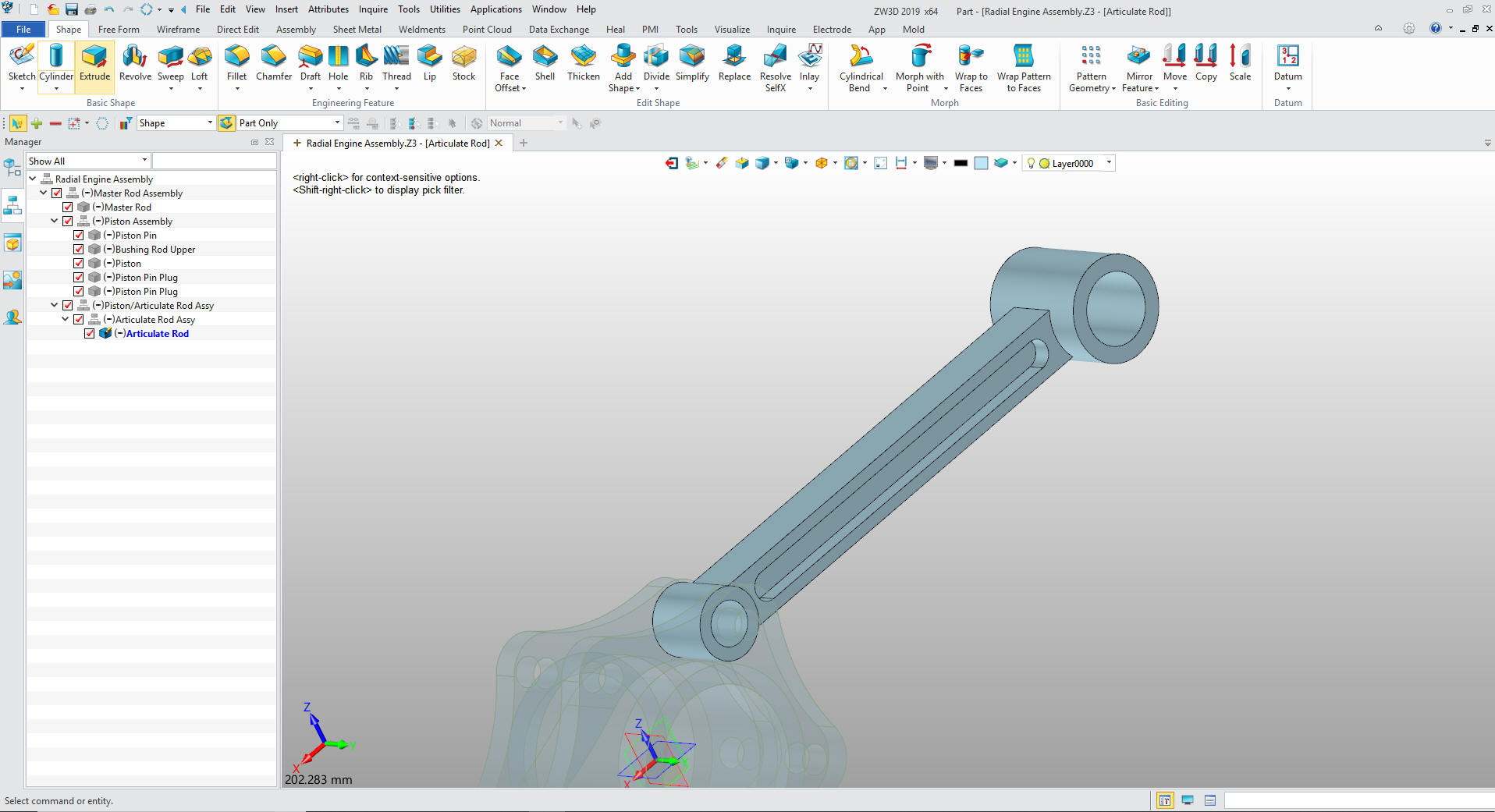
the Articulate Rod Assembly under that. We now create the
articulated rod under the Articulated Rod Assembly.
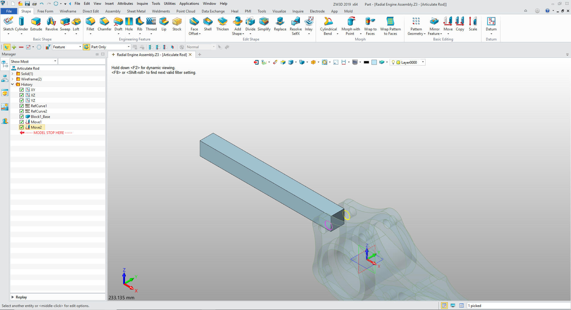
We look
at the shapes that make up the rod an see that it is basically a
block.
We insert a primitive block, locate it and size it. We
will leave it horizontal then move it into place.
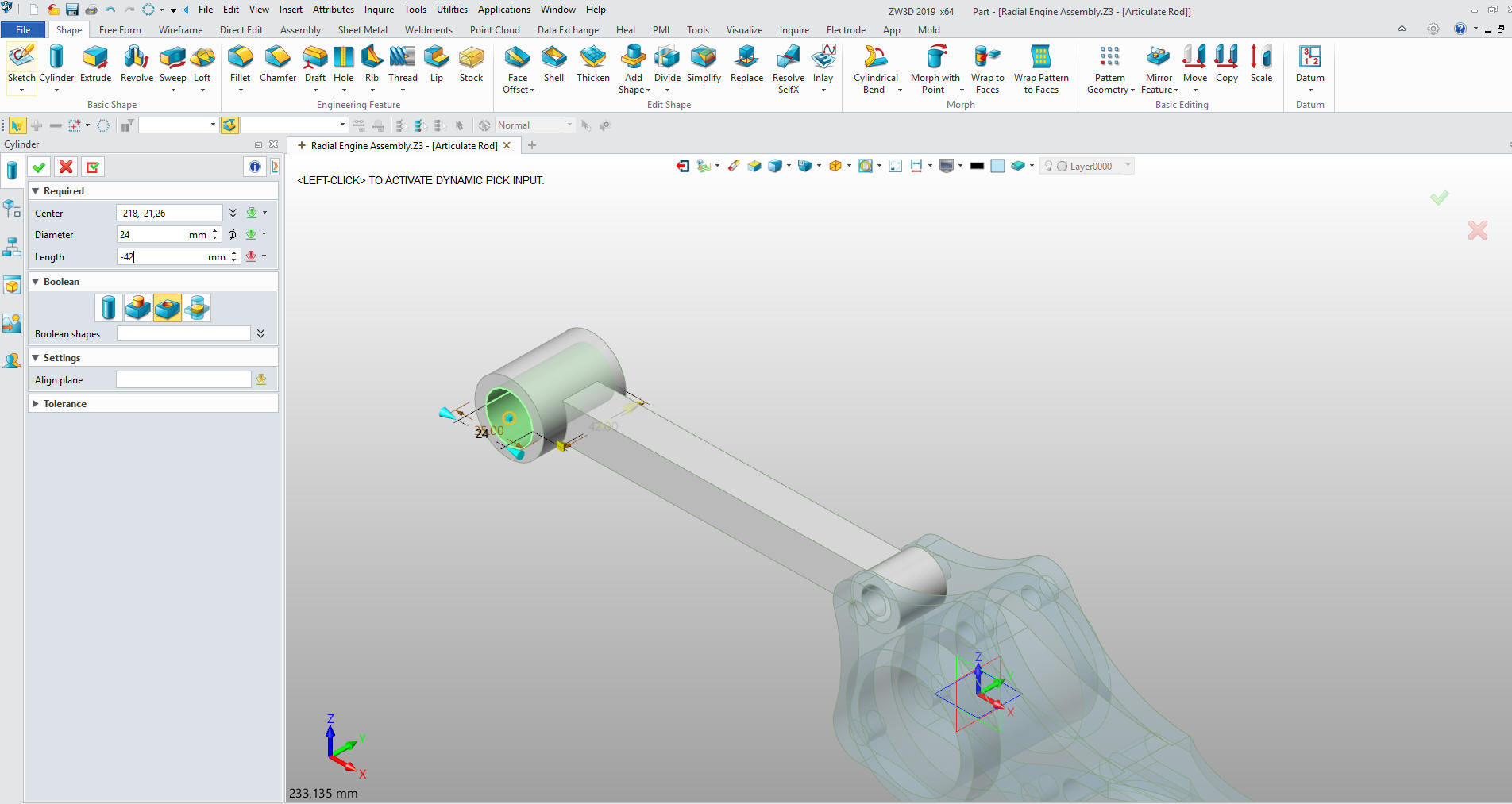
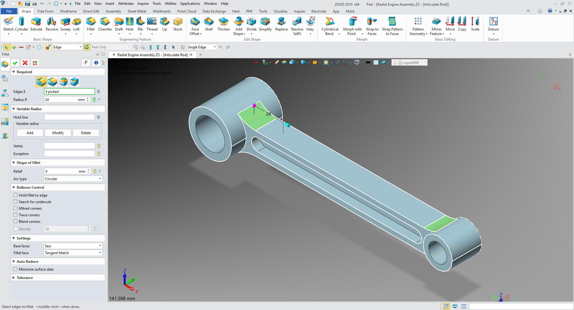
We
will insert primitive cylinders on both ends with the center holes.
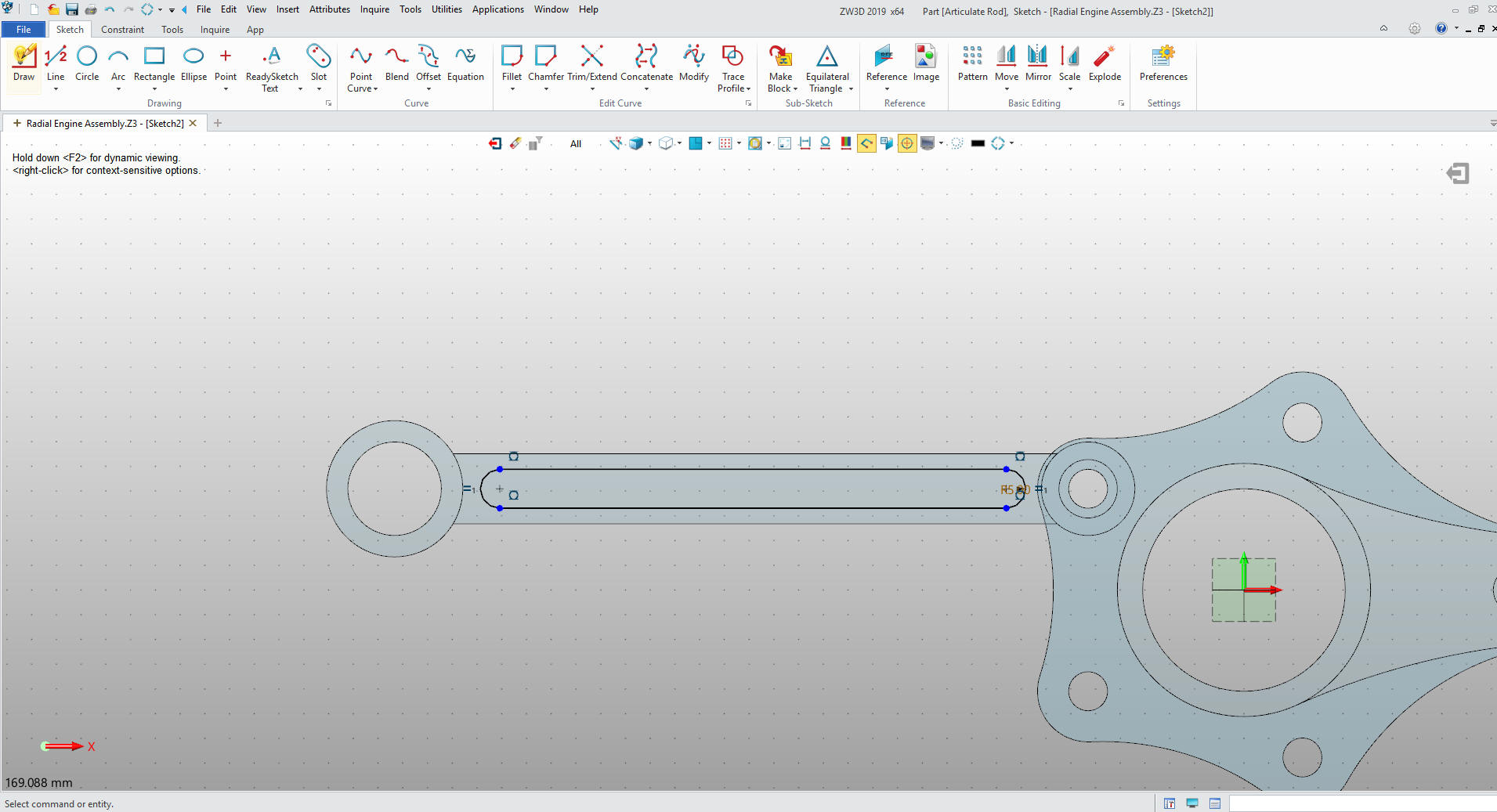
We now create the slot. We create a sketch on the face of the rod.
We exit the sketch and extrude the slot.
We
mirror the slot and we are done with the rod.
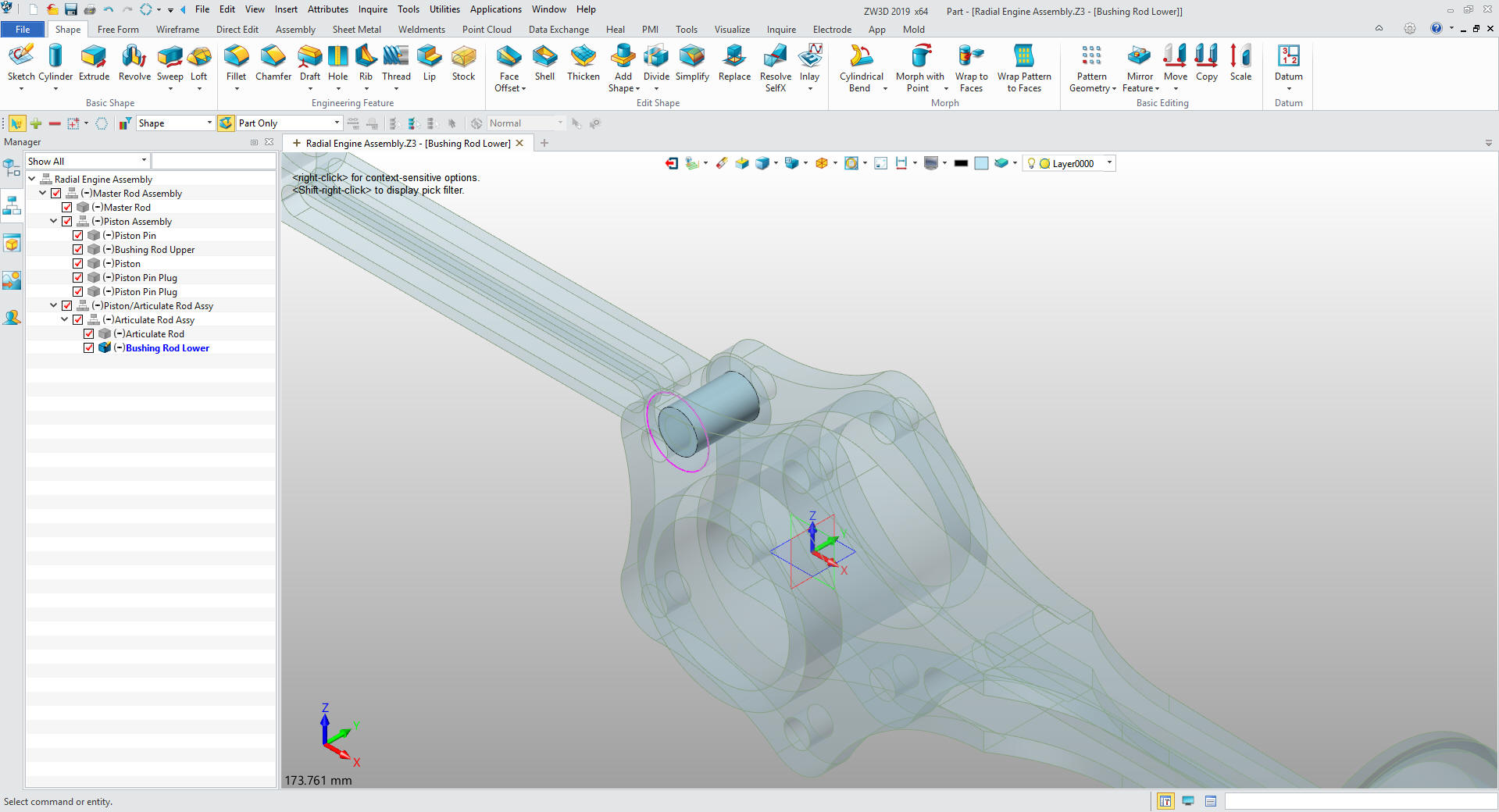
We
now create the bushing rod lower under the articulated Rod Assembly.
Yes, just insert a primitive cylinder to the a referenced center and
size it and another in the center, size and set to remove. I know
you have the idea.
Oops,
I forgot the fillets. While I was doing the detailing of this part I
realized I failed to put in the fillets. This one of the reasons
that fully detailing your parts are so important especially when you
are converting drawings. The trend to
minimized dimension is a recipe for disaster by opening the door to
Mr. Murphy.
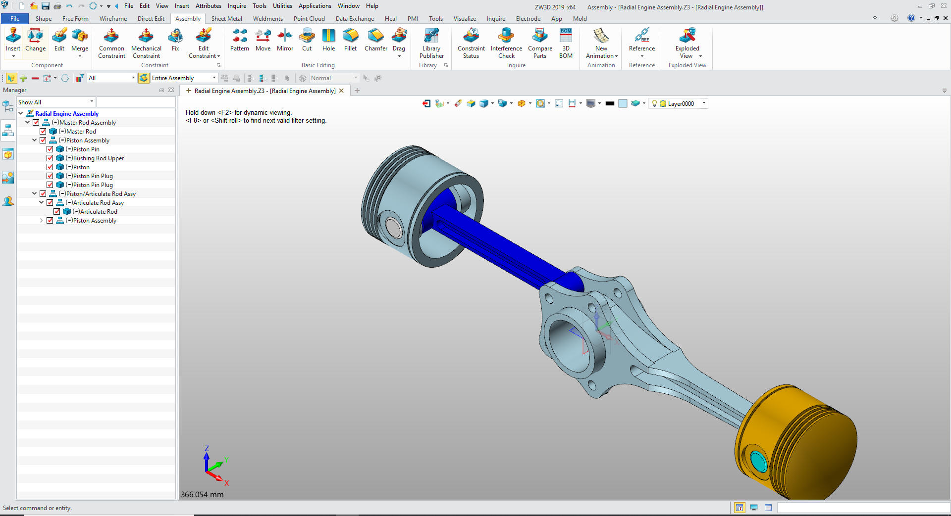
Change the color of the rod and will insert a piston into the piston
articulated Rod Assembly an move it into place.
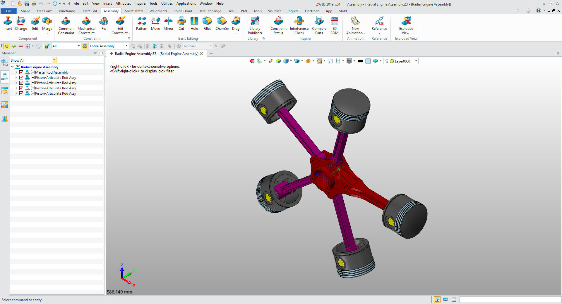
We
will copy the rest of the piston/articulated rod assemblies and
rotate into
place. We will change some colors.
Oh Oh
i forgot the piston rings. No problem.
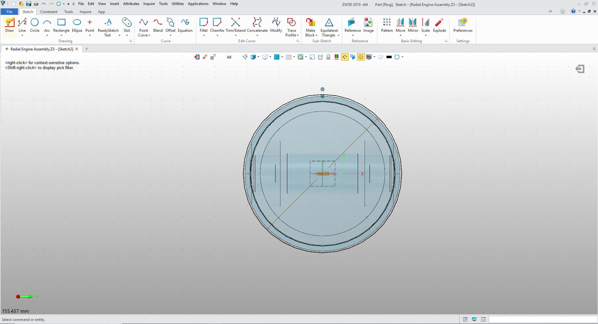
We insert the ring
under the Piston Assembly. We create a sketch on the top ring
groove.
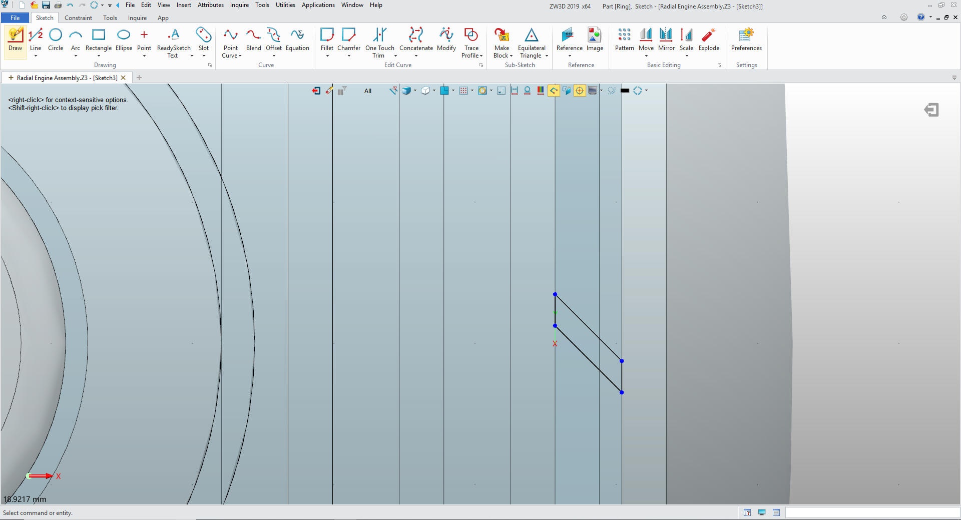
We
extrude the ring and create a sketch to create the cut.
We
extrude the cut and we are done the the ring. We copy the other 3
rings.
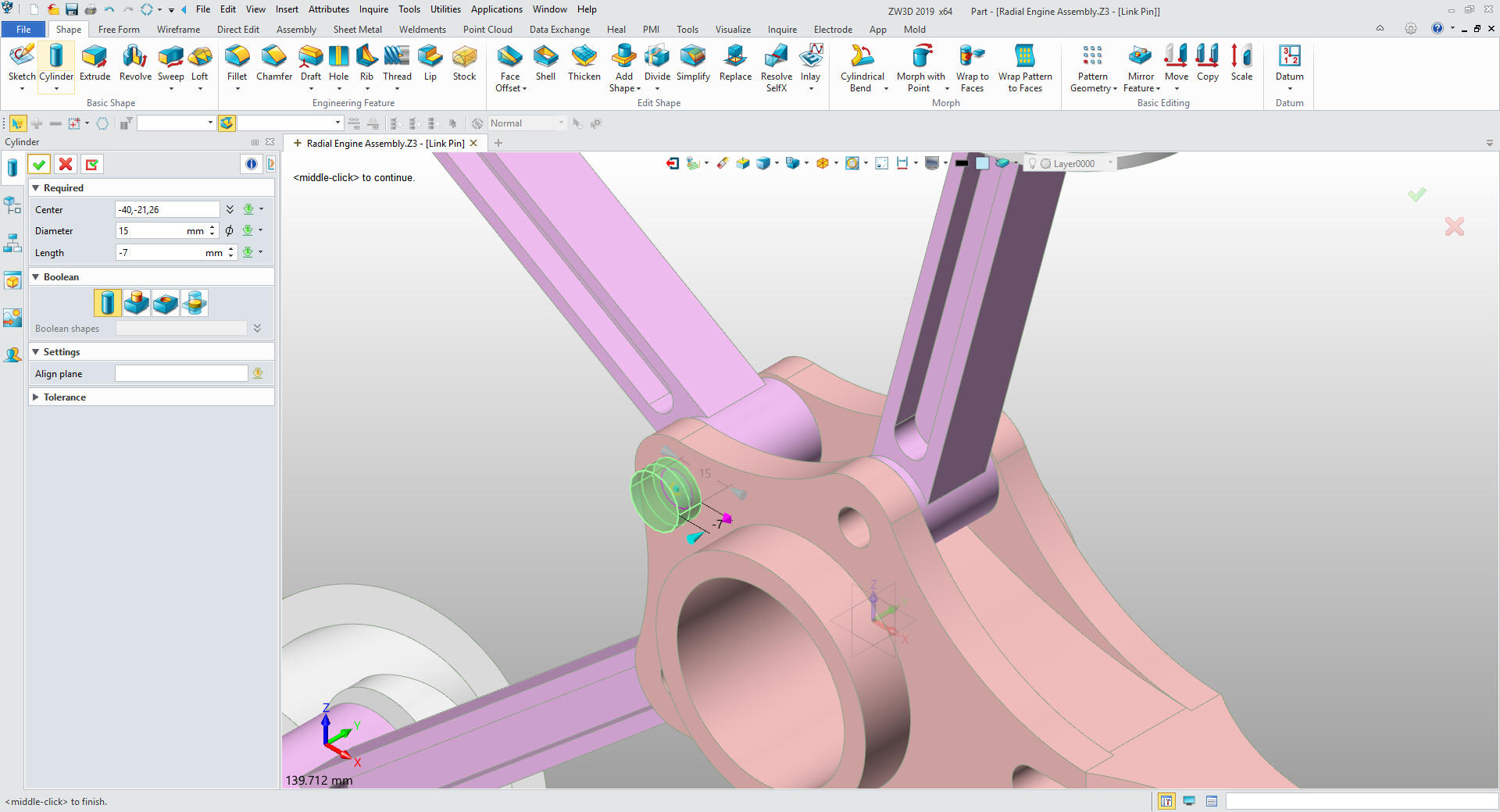
Now
for the link pins we insert them under the Radial Engine Assembly.
Insert the two primitive cylinders and size them creating the link
pin. We copy them to the other holes.
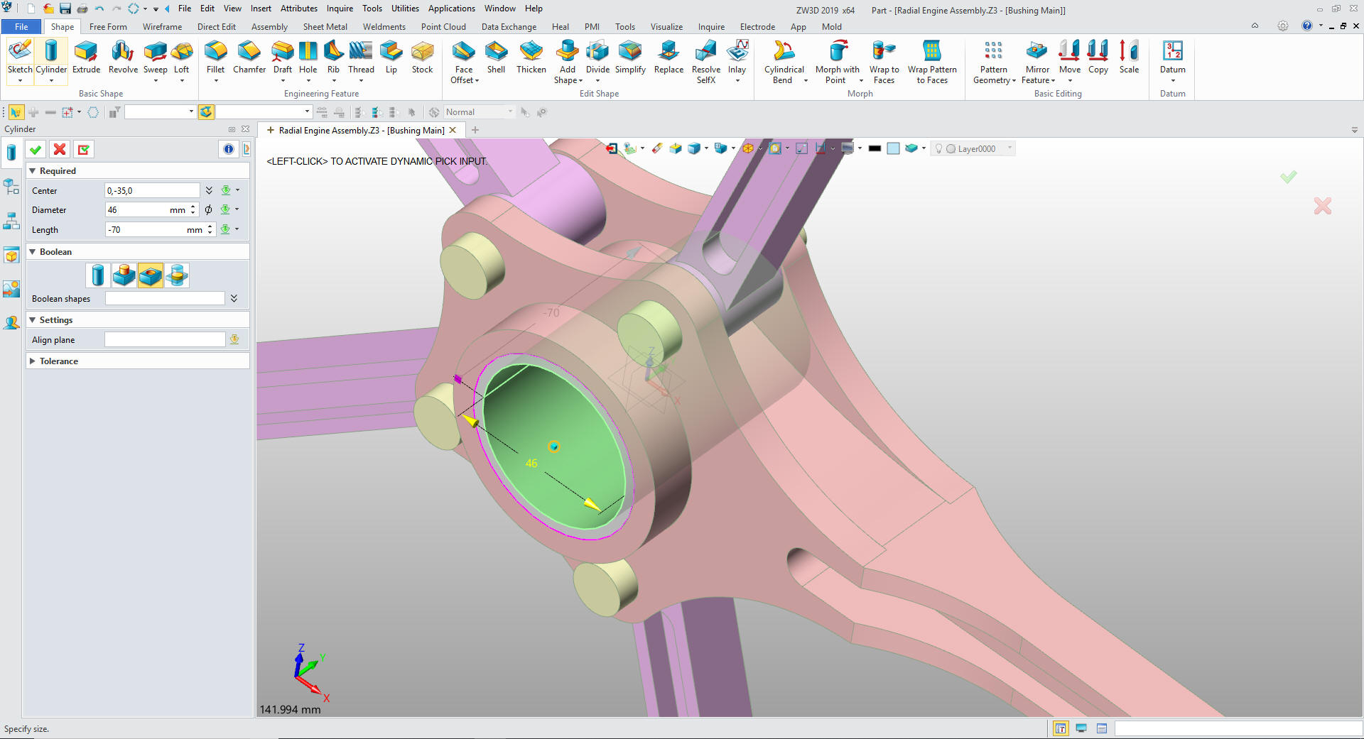
Now
for the Main Bushing just reference entity and two primitive
cylinders.
We
change the color of the Bushing and we are done.
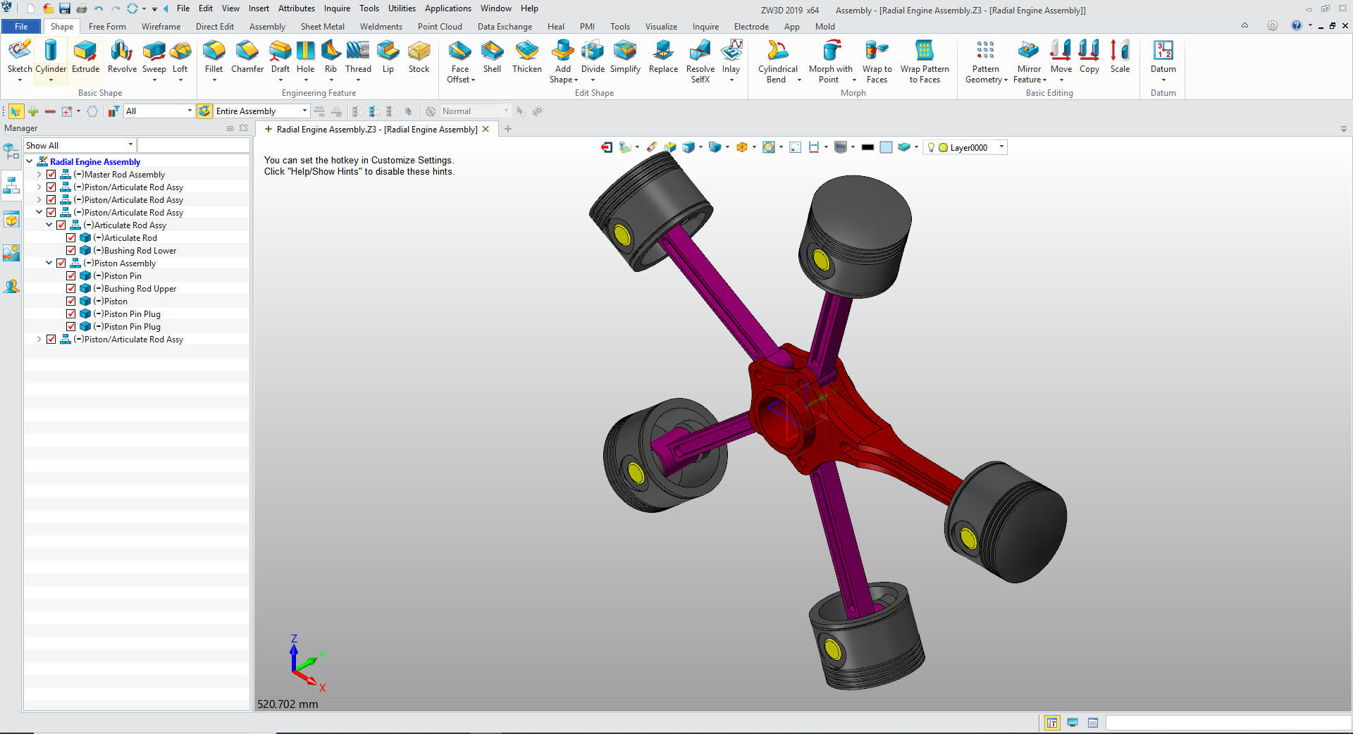
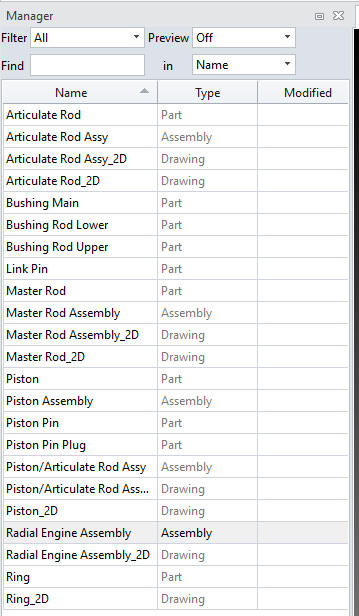
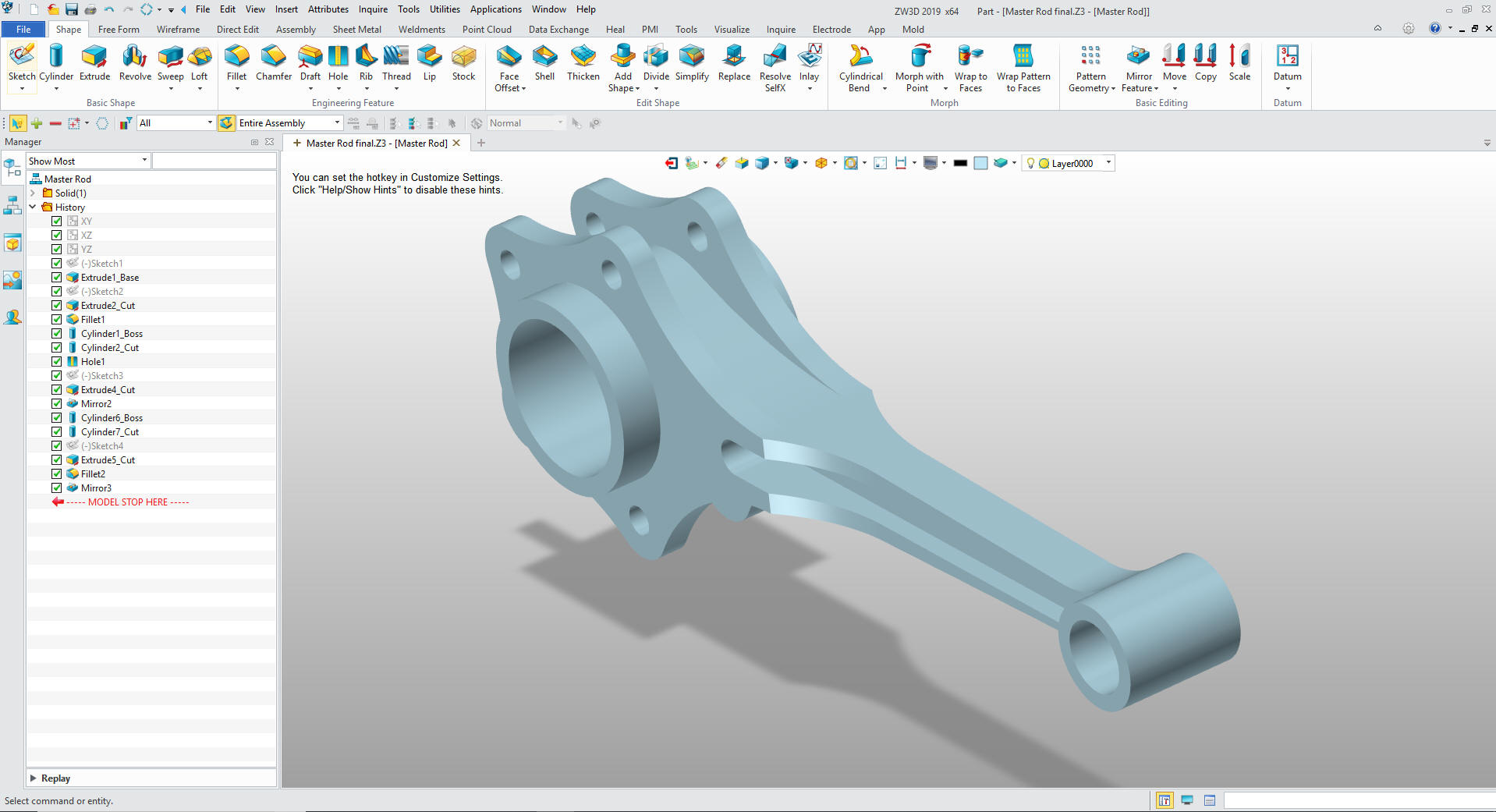
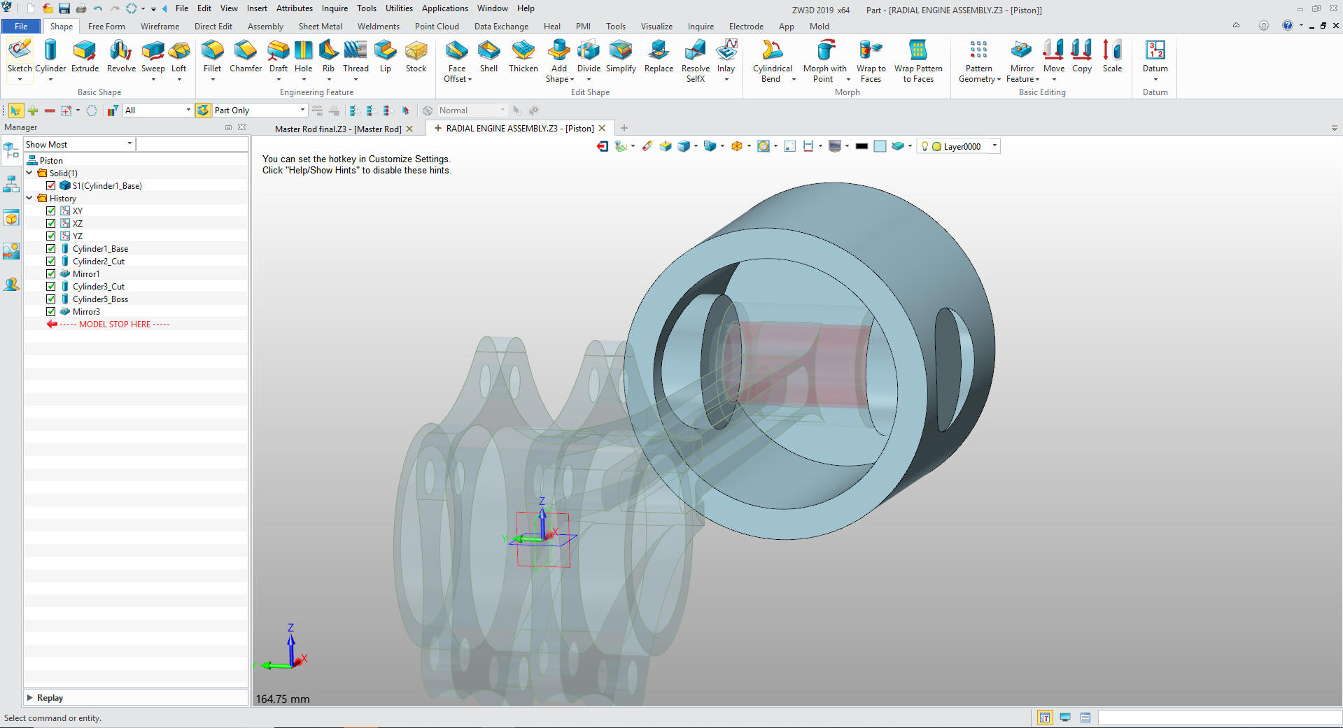
Here is our
Manager with all of the parts, sub-assemblies and AIDs (drawings) defined.
Imagine the problems with PDM this
would solve. Yes, you can have external parts and
sub-assemblies.
ZW3D is
the only history based system with integrated AIDs (drawings)and with
multi-Object environment ZW3D can have a complete project in one
file.
Here are the AIDs (drawings). How would you do these parts and
assemblies?
This format is called the detailed assembly.
We could have easily just given each AID an individual AID
number.
Here is
an interesting note. This is a detailed assembly, which means all of
the parts are under one document number. I found that I would have
to put the combine parts such as bushings and pins in one sheet. I
put them under the main assembly. I ask myself, "How would someone
following up on this job find them?" Then I realized that I could
create a new part called AIDs (drawings) and do all the AIDs under
that part file since ZW3D has all of the parts available no matter
what part or assembly you are creating the 2D sheet from. It is
very important that you look into how you or your engineers are
creating the parts. Streamline Sketching and Feature Based Modeling
is easy to learn and implement. It, alone, will increase
productivity 10X. Now, ZW3D with its unique history and robust
direct edit functionality can increase your productivity another 5X
or more with changes! Again, time is money in engineering.
More on StreamLined Sketching and Feature
Based Modeling.
To experience this increased level of
productivity, please download ZW3D for a 30 day evaluation. Legacy
data is no problem, ZW3D can read the native files of all of the
popular programs including the PMI data of NX, Solidworks, Catia and
Creo. ZW3D is a great replacement for the subscription only Autodesk
and PTC products.
Give me a call if you have any
questions. I can set up a skype or go to meeting to show this part
or answer any of your questions on the operation of ZW3D. It
truly is the Ultimate CAD/CAM System.
 We
We