|
IRONCAD vs CATIA Lesson 3 Assembly 3D Modeling Techniques Defined True Top Down Assembly/In Context Design vs Separate Part Design With Streamlined Sketching/Feature Based Modeling In a Single Model Environment Two Files compared to Thirty? | ||||
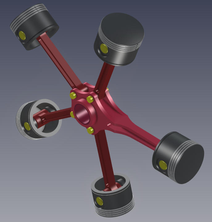
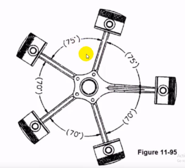
While creating 3D models from a drawing is the very best way to learn 3D CAD and maybe some design techniques is does not expose the designer to the design flexibility necessary in product design. IronCAD is all top down due to the single model environment. Its in-context functionality makes creating mating parts a cruise. But effective modeling is just one aspect of a well designed productive 3D CAD system. IronCAD vs CATIA I would do a video, but I really am not good at it. So I will show you step by step. I will try and get IronCAD USA to create one. They are very good. I usually create the part before I watch the Video, so as to not taint my process, but this time there was no drawing so I had to suffer through this presentation getting the dimensions. Of course, there are a multitude of ways to create a model. There is no right way, just more productive ways. But from what I have seen from these very complicated processes done by the CATIA presenter, it is not just limited by the 3D CAD system. I have to say this is incredibly simple. But the CATIA presenter has been indoctrinated into these designs techniques. It started with Pro/e (Creo) and has been the way the sketch, constrain and assemble. The Solidworks clones are costing the industry millions, if not billions, in lost productivity. I actually created this part by studying the CATIA presenters video since there was no drawing. It was a bit torturous. But I finally got it modeled and then created a fully detailed AID (drawing) and did it again to optimize the modeling process. I had to refined it to a bit better designed model. You can see by the AID (drawing) it is a very simple part as compared to the poor CATIA user. Sadly, we can model anything. But I believe all 3D CAD engineers should understand basic machining to be good designers and modelers to provide concise, completed, unambiguous and inspectable documentation. CNC Machining Design Guide The Master Rod I actually did the Master Rod in this article. IRONCAD vs CATIA Lesson 2 We don't have to set up anything just rename the file and started adding parts. Another advantage of designing in the single design environment. I will go through the Master Rod creation again here. Here is IronCAD. We will set the units to millimeters. Learning IronCAD! Lesson 1 Setting up the Scene (Workspace) 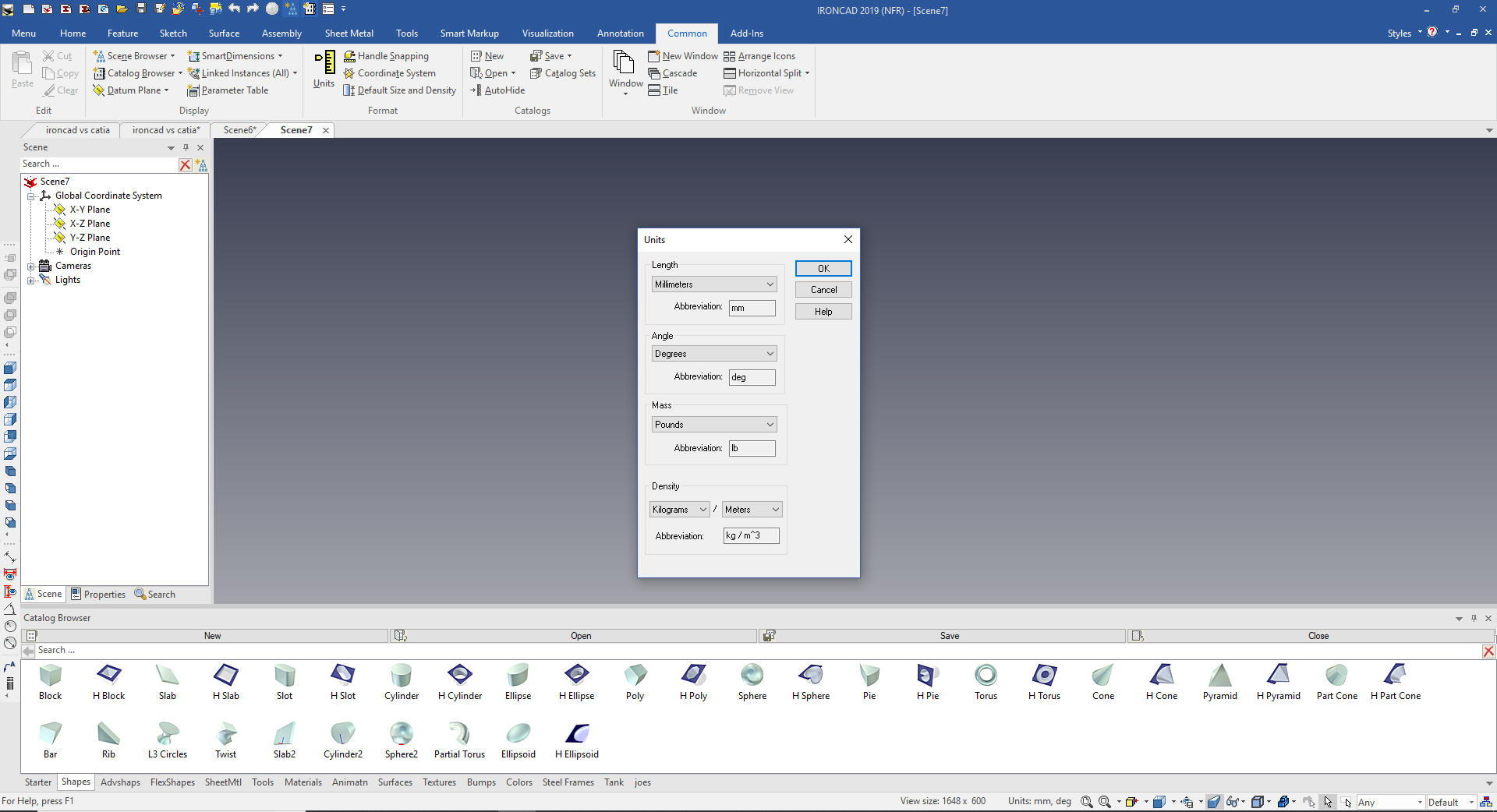 IronCAD has two sketching features The Standalone that allows you to sketch and save the sketch at any level of completion, this is used when creating a complex sketch or when importing .dxf or .dwg to use to make 2D into 3D. The sketch wizards instantly turn extrusions and spins into a solid model so the sketch has to be correct. You use this when creating new features or mating part by projecting mating edges. Learning IronCAD! Lesson 3 Streamlined Sketching (Unconstrained Sketching) We will start by creating a standalone sketch on the YZ plane. 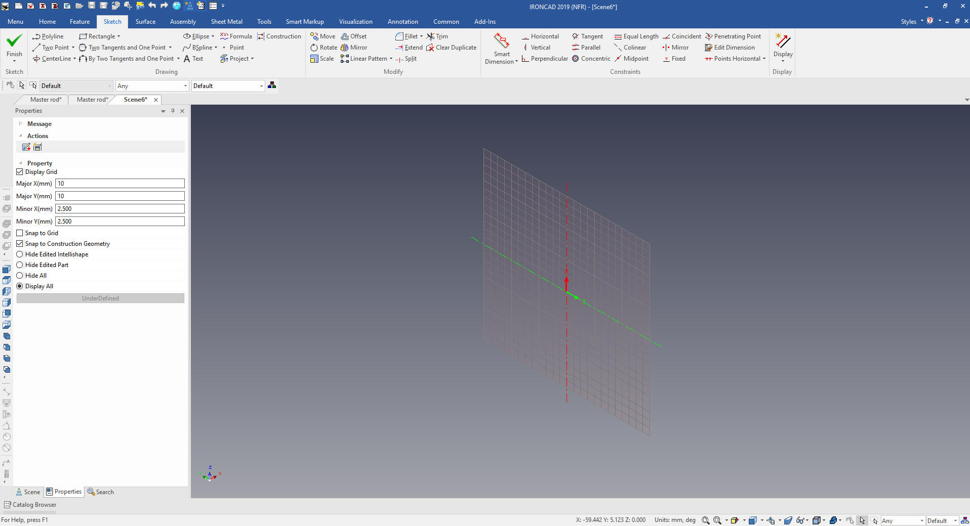 We will look into the plane and put in a few lines to use for reference. 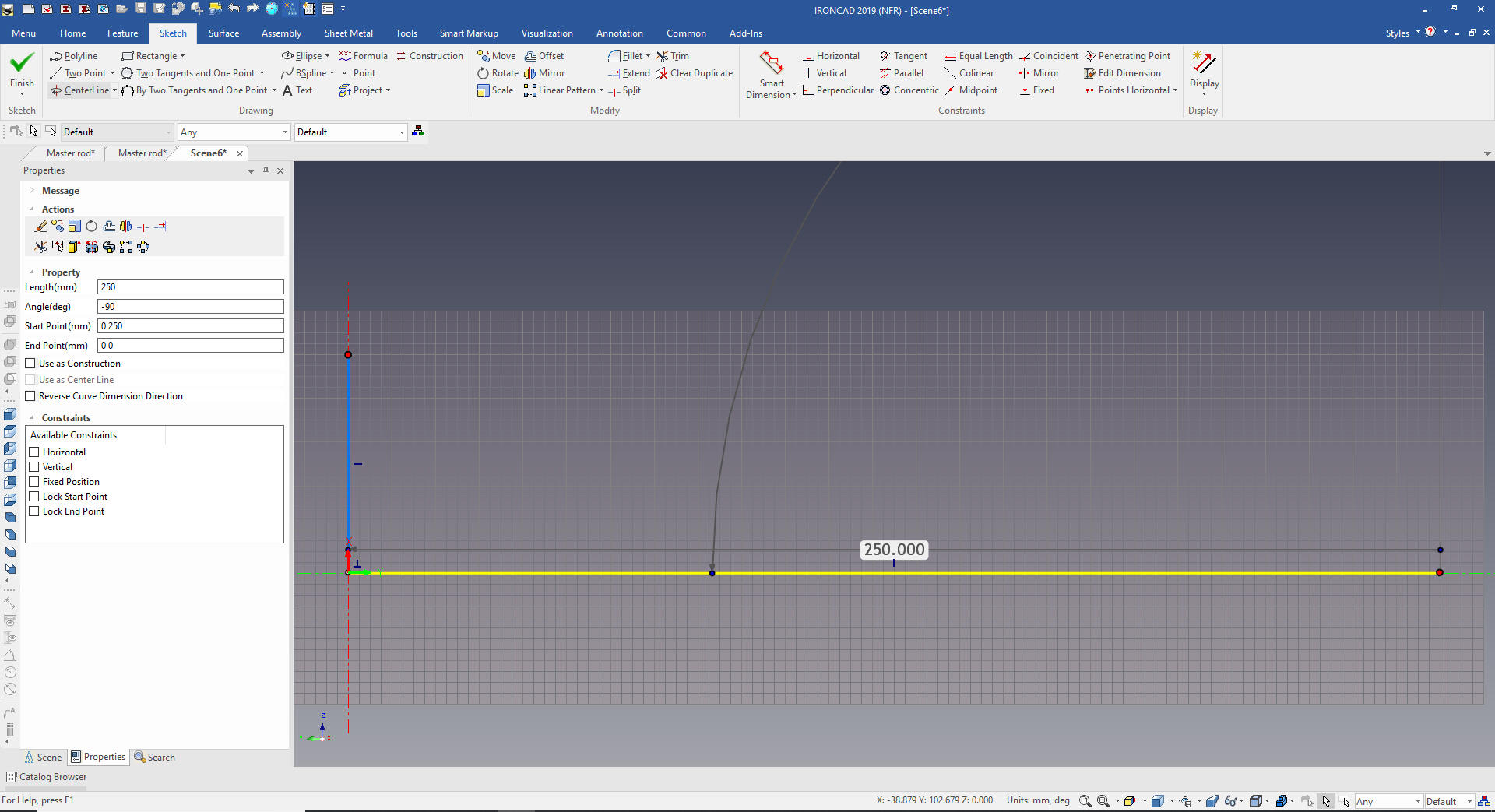 We offset copy some lines and trim/extend as necessary to locate our first circles. 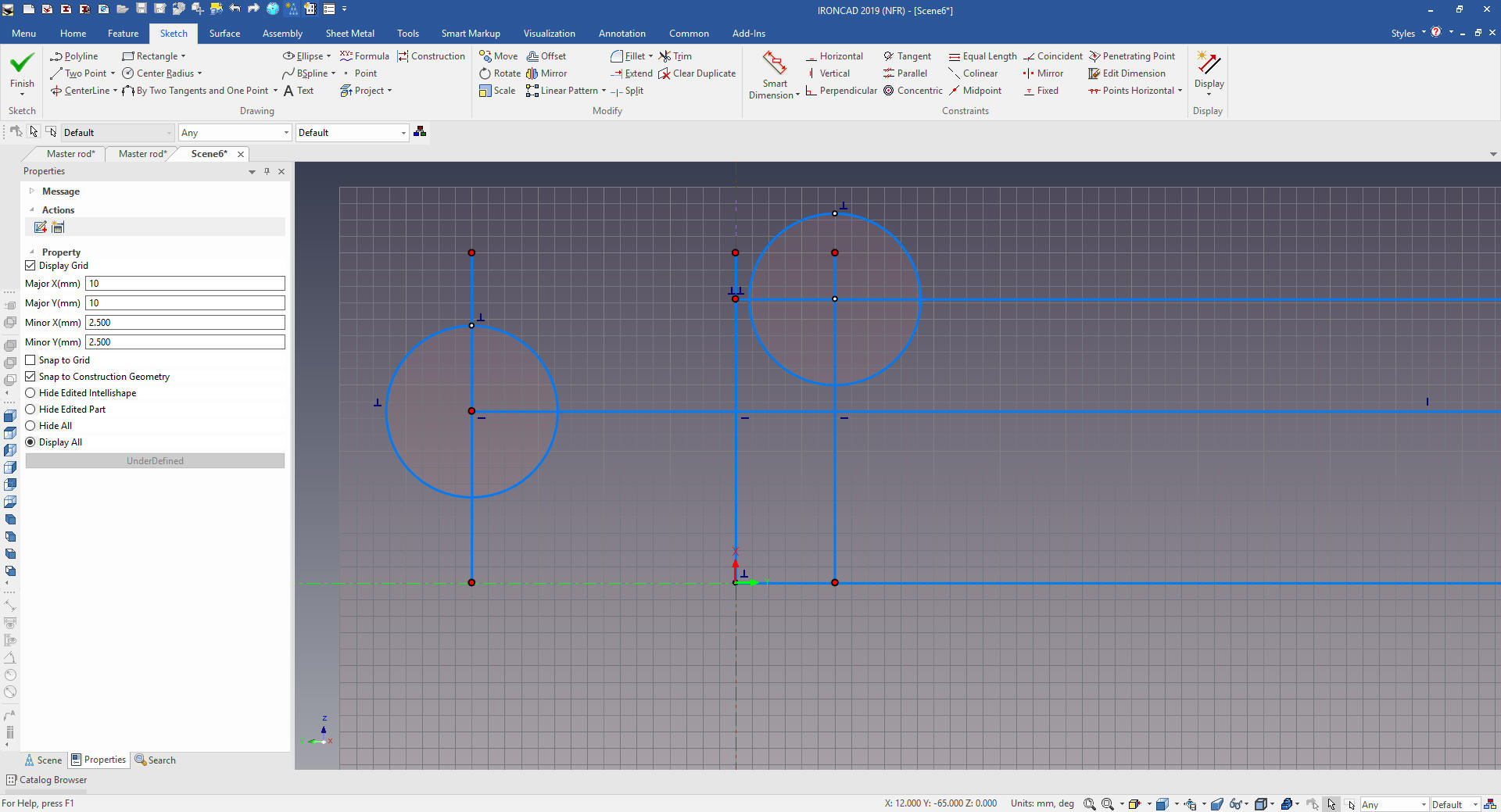 I delete the reference graphics. The Catia fellow locks an arc to locate the angled edges. Now this is fine for a CAD jockey I have to think about how this part is going to be documented. I am hardly going to dimension the end of an arc on an angled face! Do I will defined this edge by offsetting two lines and set their length. We connect the ends and extend the line. We create two arc with two tangent and a point. I first thought i would define this edge with these two points, but as i was detailing the part, I defined this edge with and angle and distance in the AID (drawing) which makes it much easier to create the model. See the AID (drawing) below. 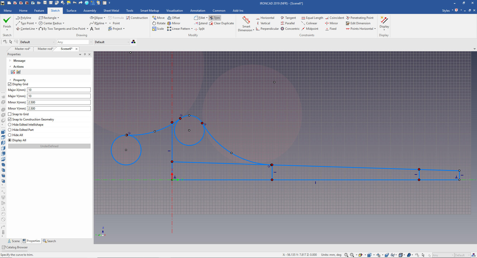 We clean up the extraneous graphics by deleting or trim/extend. We select the graphics to mirror. I don't understand why the Catia fellow only created half and then mirrored the solid. I feel in this case it was easier to create the complete sketch when there are so few entities. 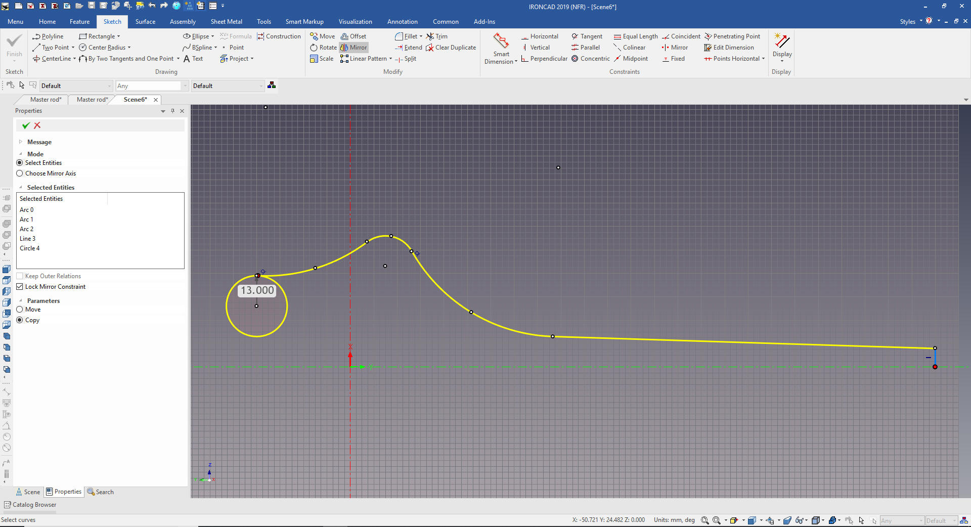 We mirror and add the last arc, trim and extend. If you look at the CATIA presenters left end arc it was not tangent. Even when we are doing examples we should focus on correct part design. Note: This is one of the reasons I don't recommend minimized detailing. You can miss such obvious error. But it sticks out like a sore thumb when you create a fully detailed AID. I add the hole in the middle for reference later. The difference between a CAD jockey and a designer is the consideration of the documentation. 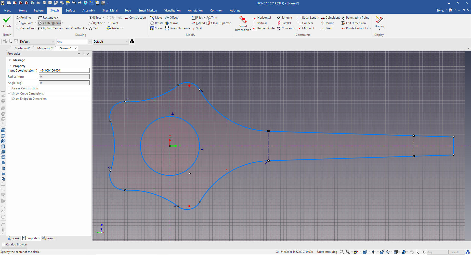 We are done with the sketch. 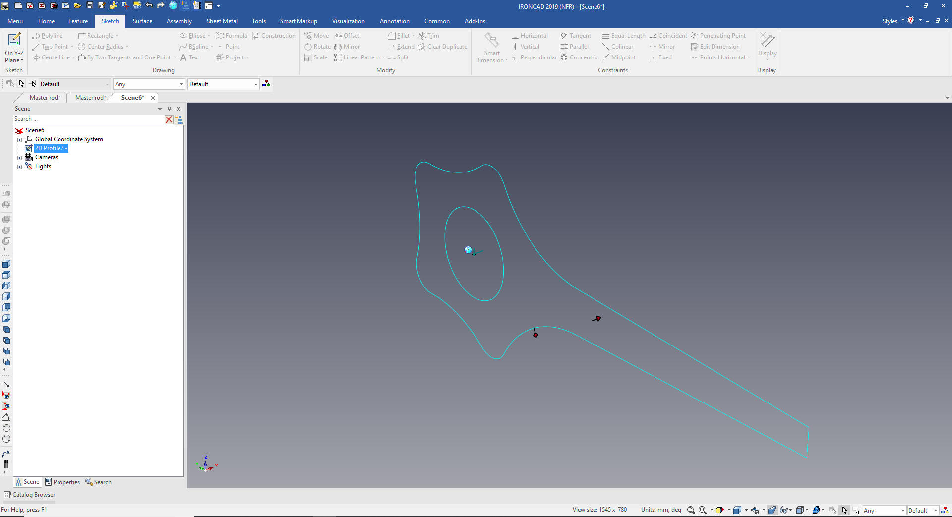 We now select the sketch and create extrude to the 42m. 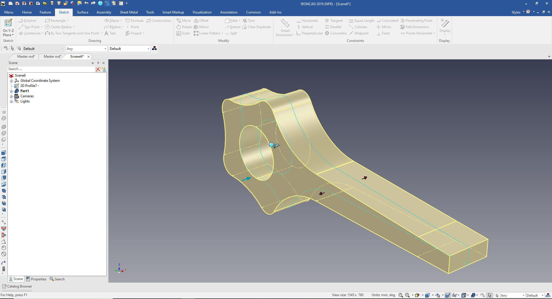 Now for the center cut we create a standalone sketch on the YZ plane. Project the lines and offset the circle and create a rectangle to create the cut out sketch. 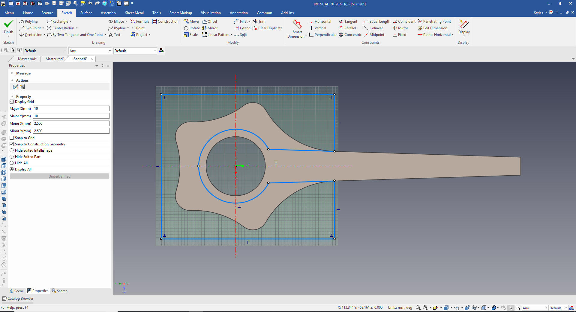 We will extrude and set to remove from the existing solid. 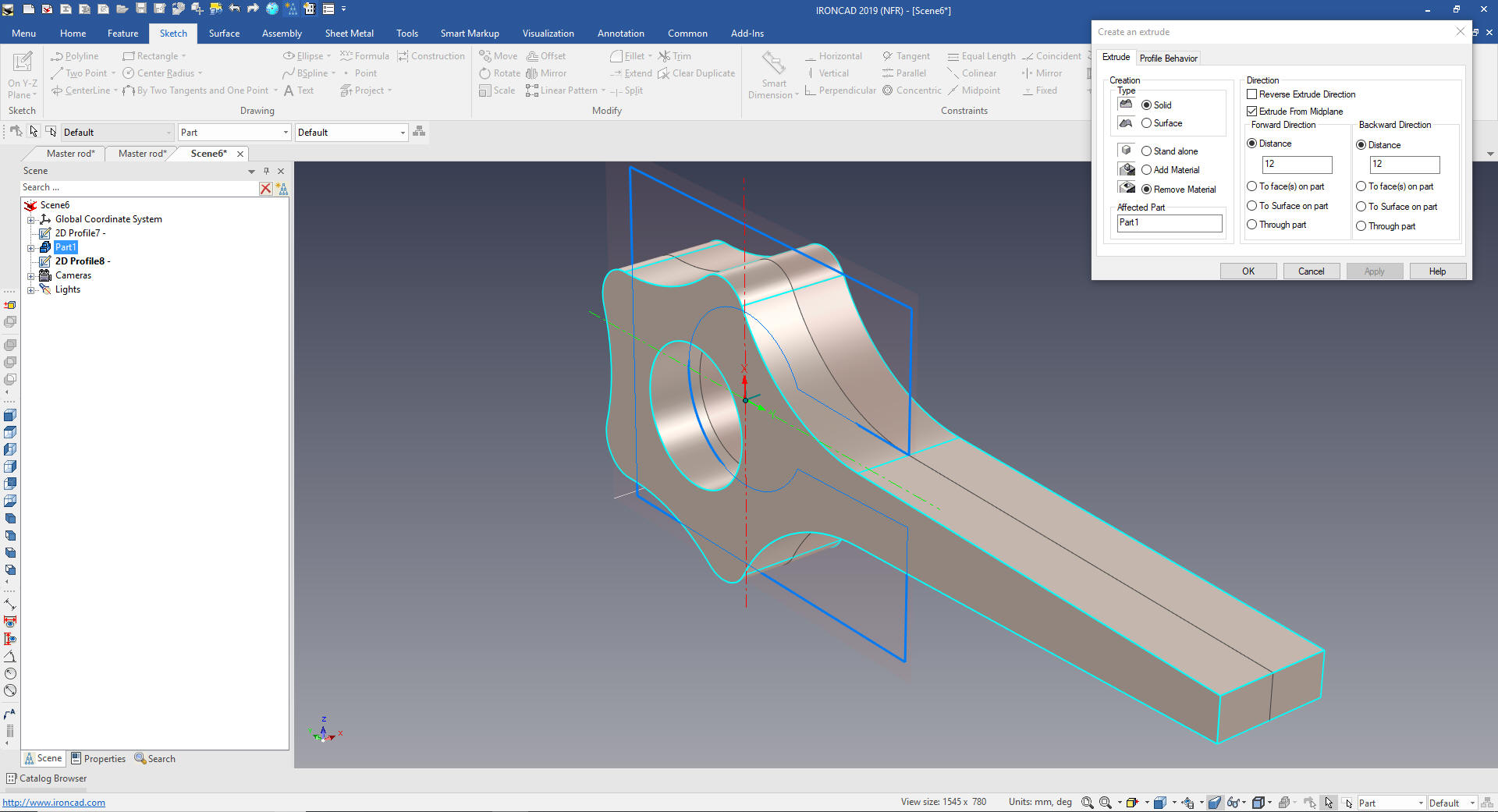 We now need to add the 190m blends. 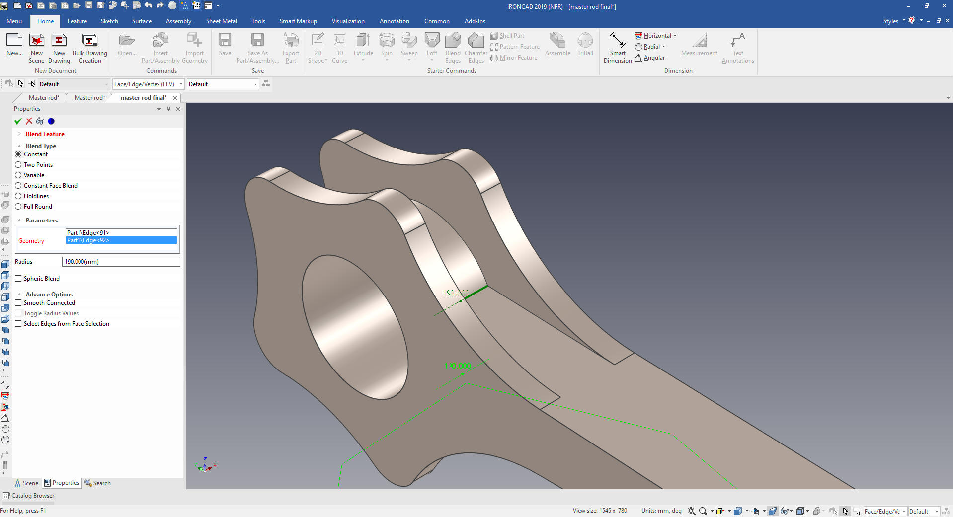 We now add the center boss and hole by dragging and dropping a cylinder then a hole cylinder from the catalog and size them. You can see I have enabled the catalog so you can see it. Usually it is hidden for more scene landscape. Learning IronCAD! Lesson Two Drag and Drop Design Designing with Shapes What are these shapes? We call them intellishapes. All are based on sketches that can be edited. Learning IronCAD! Lesson 4 IronCAD Intellishape Deconstructed What are we Dragging and Dropping? IronCAD was first released as Trispectives a graphic design package and they called the workspace the scene. 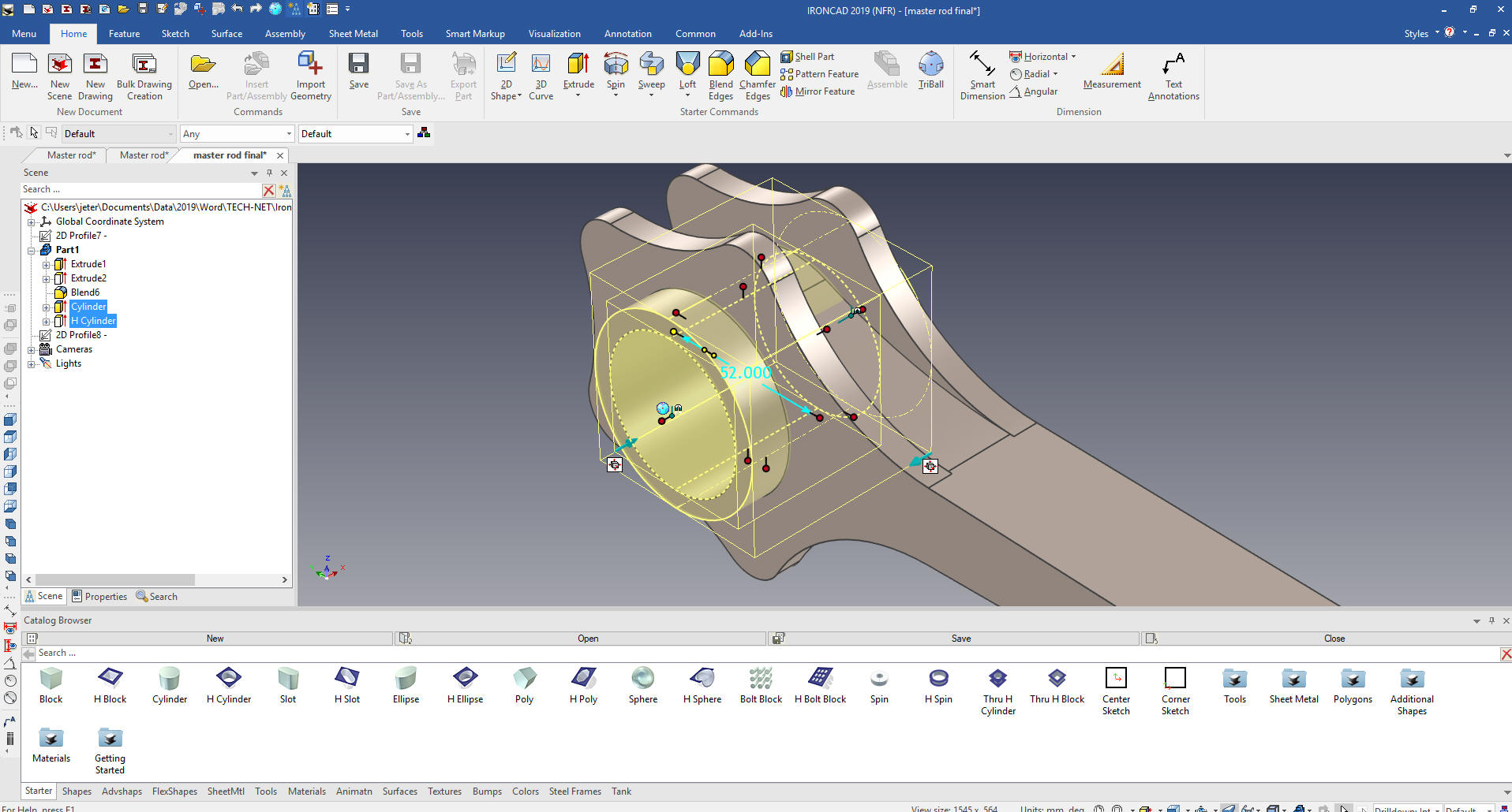 We now add the side cuts by dragging a hole block locating and size it. We mirror using the Triball and link it. 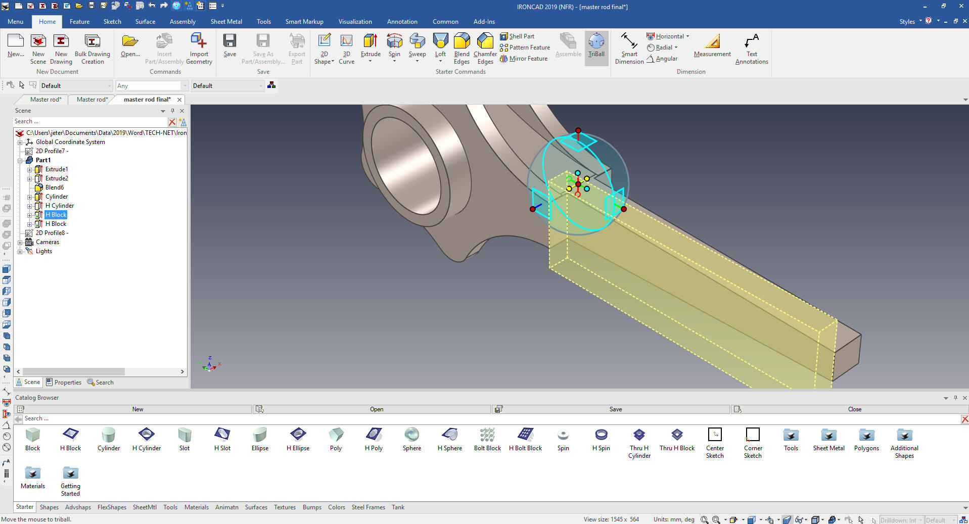 W WWe add the fillet in the cut and on the end boss and were are ready our end boss and hole. 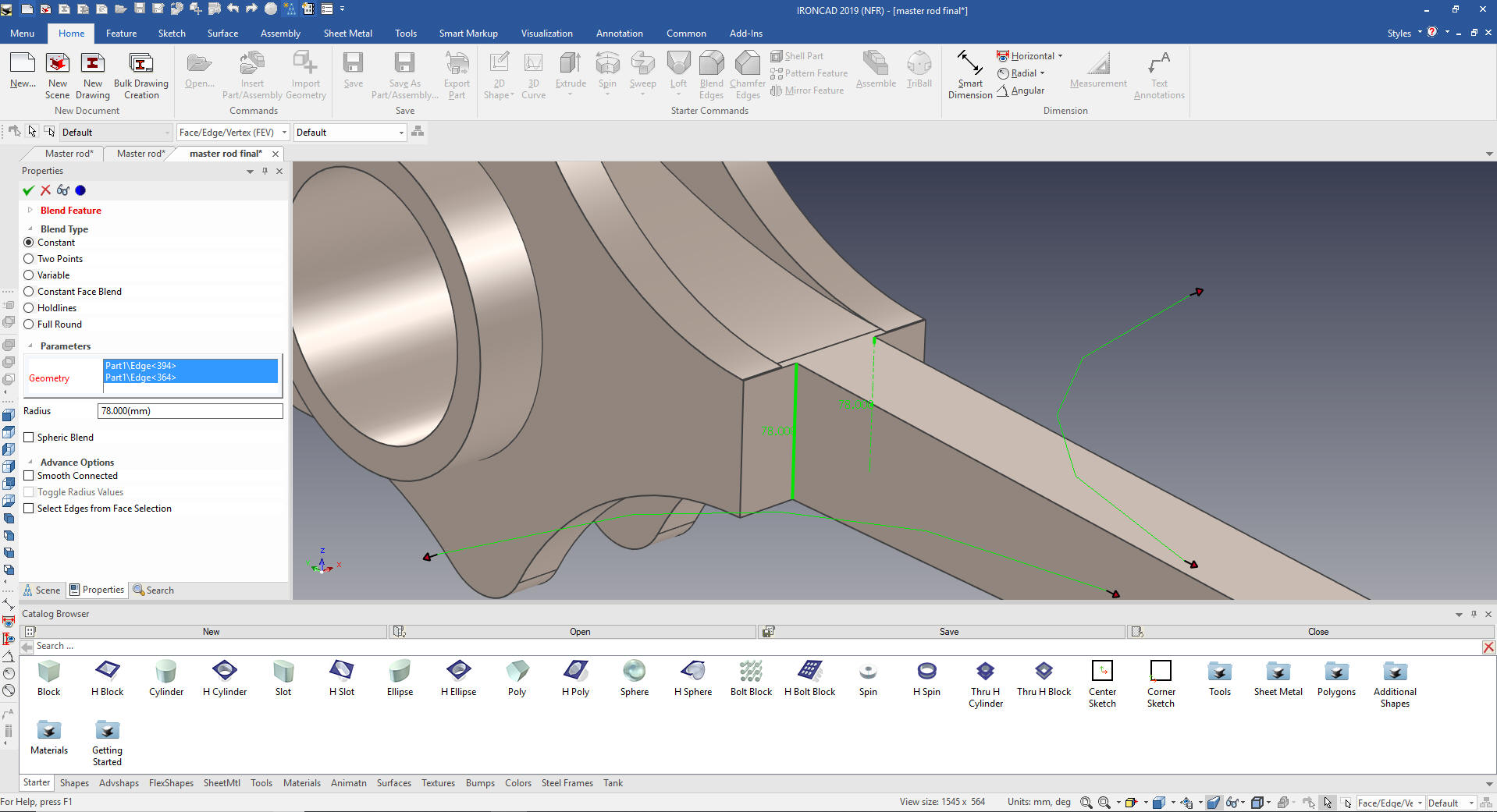 We drag and drop and cylinder on end and size it. Then drag and hole cylinder to the center of the boss and size it. 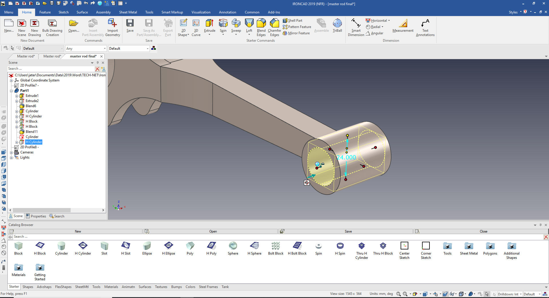 We add the blend and drag and drop a slot on a center point and size it. 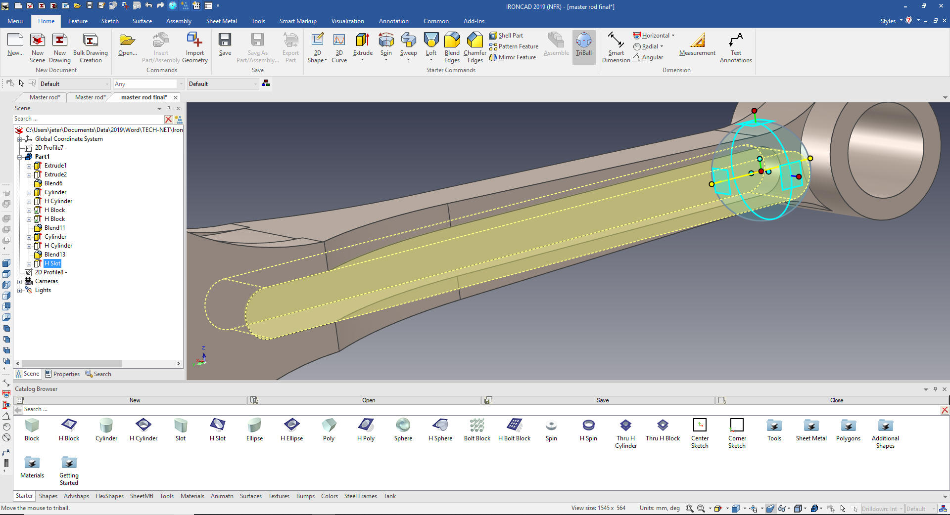 We mirror link the slot with the Triball. 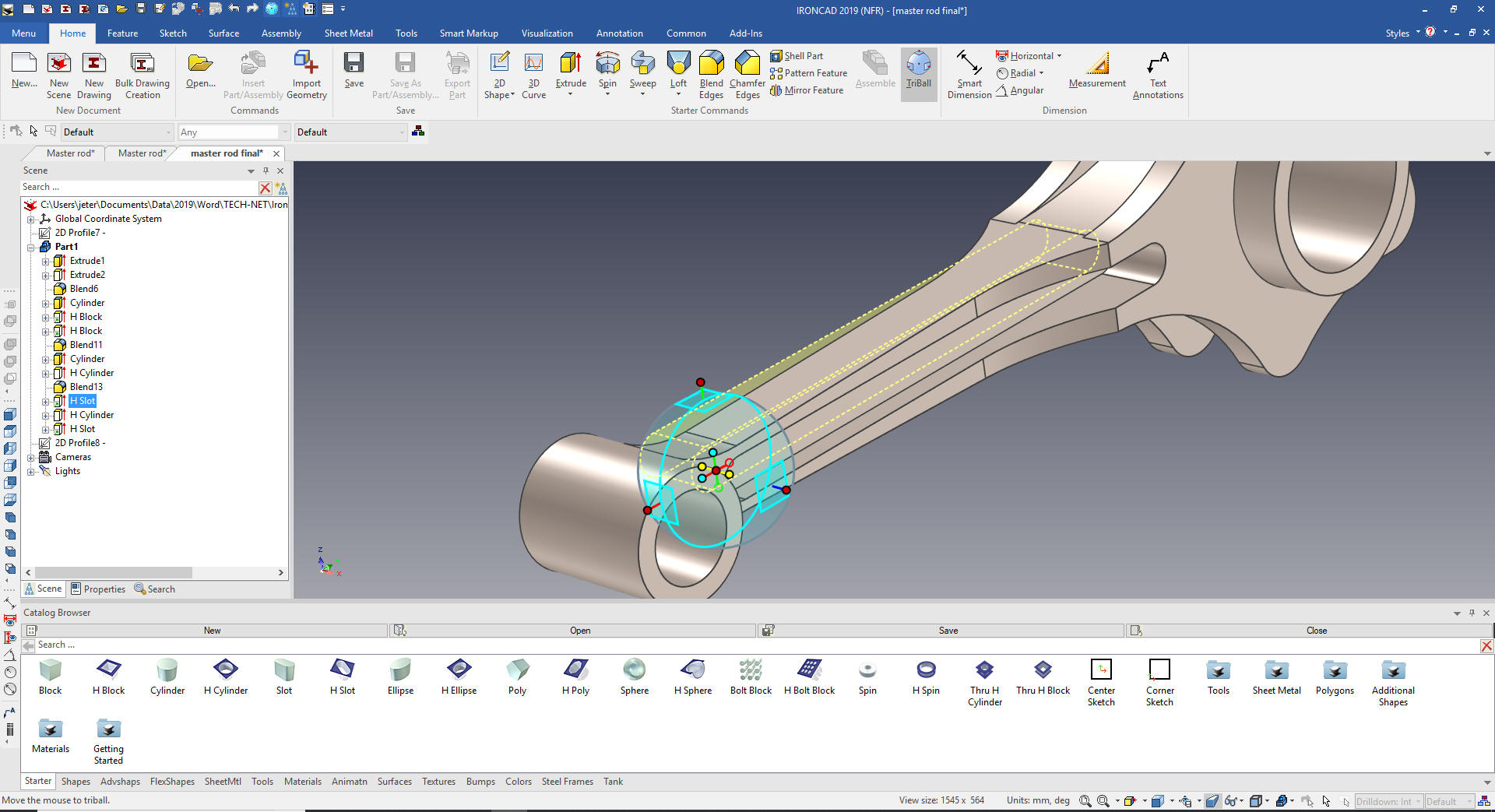 We add the 10m holes by dragging and dropping a hole cylinder on the center of one of the tabs. 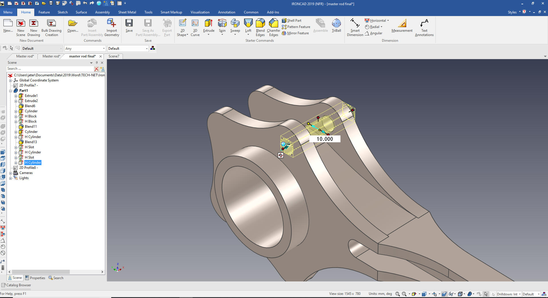 We use the Triball to link the hole to the center of the other tabs and we are done. You will see the advantage of linking when we create and install the "Link Pins" in the top assembly. 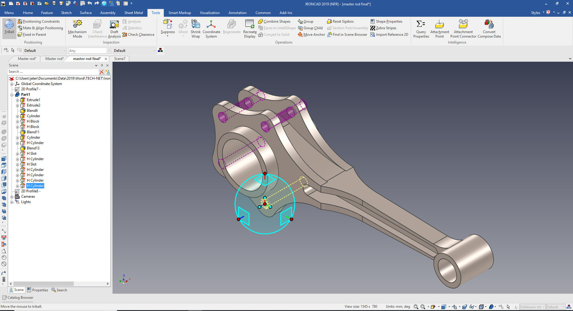 Here is the final part. We did two sketches, the poor Catia presenter made this part so much more complicated. I can't imagine hundreds of Boeing, Airbus, Gulfstream and Bombardier designers struggling with CATIA 5 and constrained sketching only. 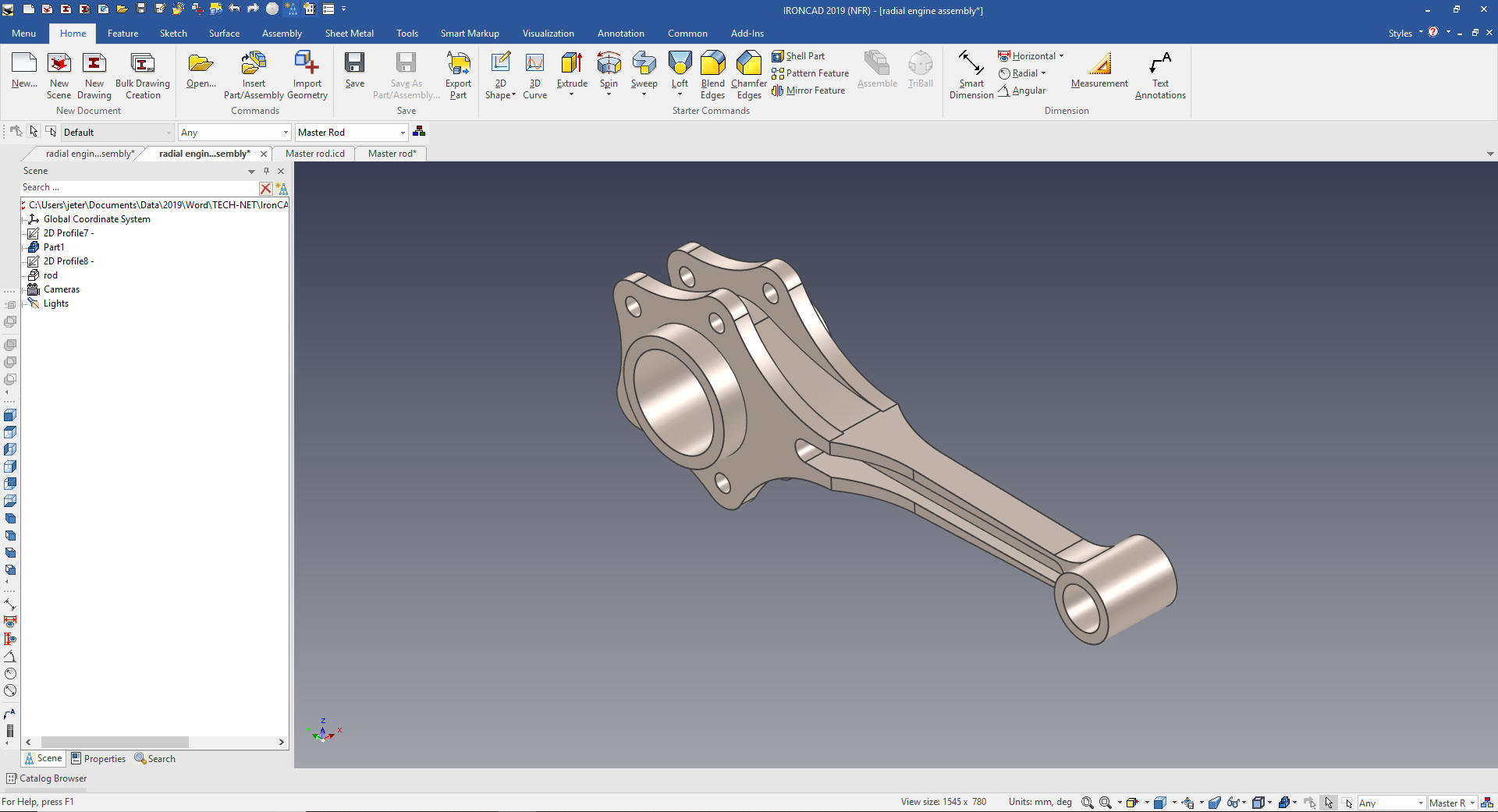 Rod Bushing Upper Now we will add the rod bushing upper. We drag and drop a cylinder using the right mouse button to the center of the right cylinder and select "Drop as Part. 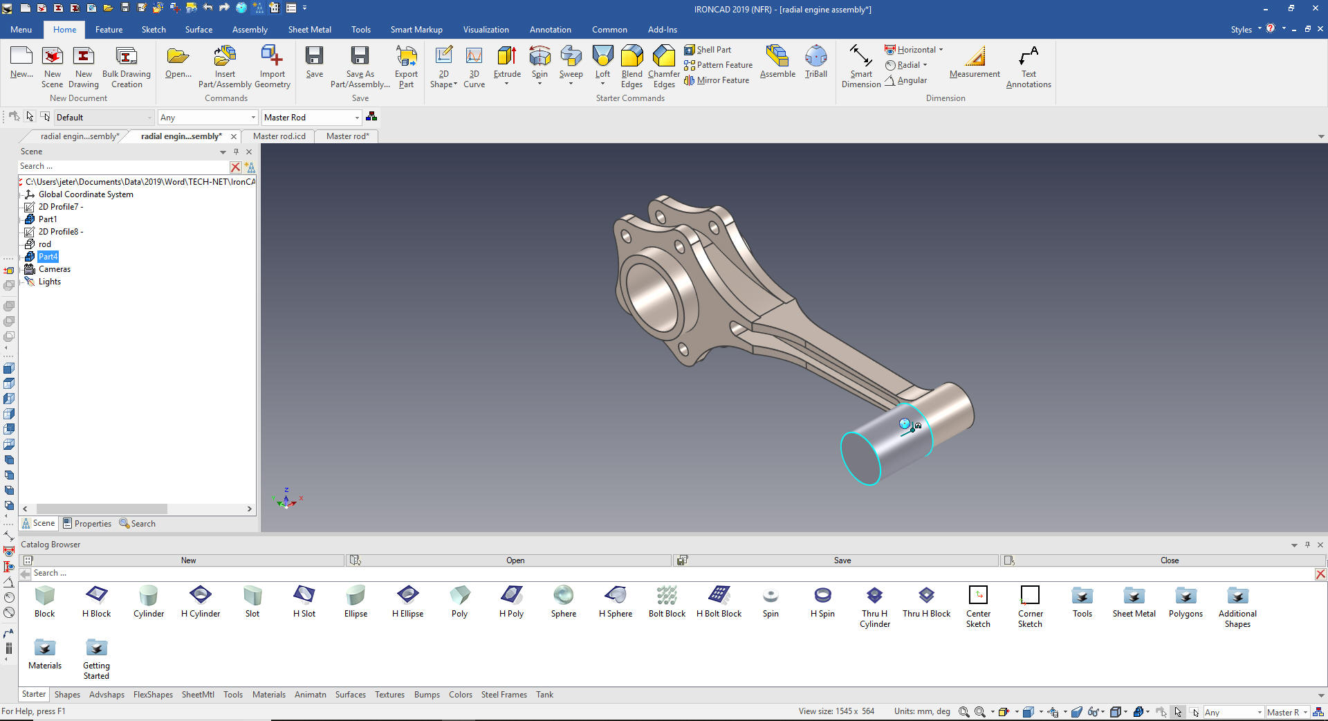 Now we locate and size the bushing and drag and drop a hole cylinder to the center and size it. We also change the name of the part in the scene browser. 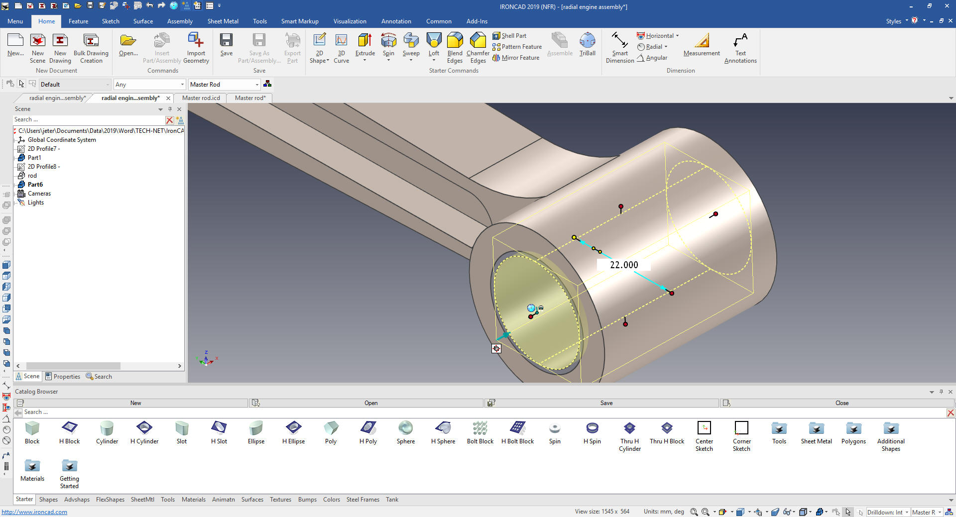 Piston Pin We now drag and drop another cylinder using the right mouse button and create a new part.  We size it, change the color, add the hole in the center by dragging and dropping a hole cylinder and sizing it and rename it to Piston Pin. 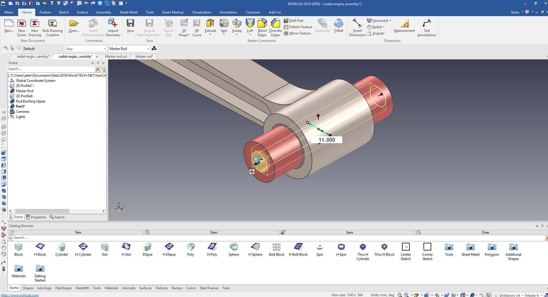 Piston Now for the piston. We drag and drop a cylinder to the center end of the piston pin with the right button to create a new part. We move it to the center of the pin hole an rotate it 90 degrees with the Triball. We size size it. 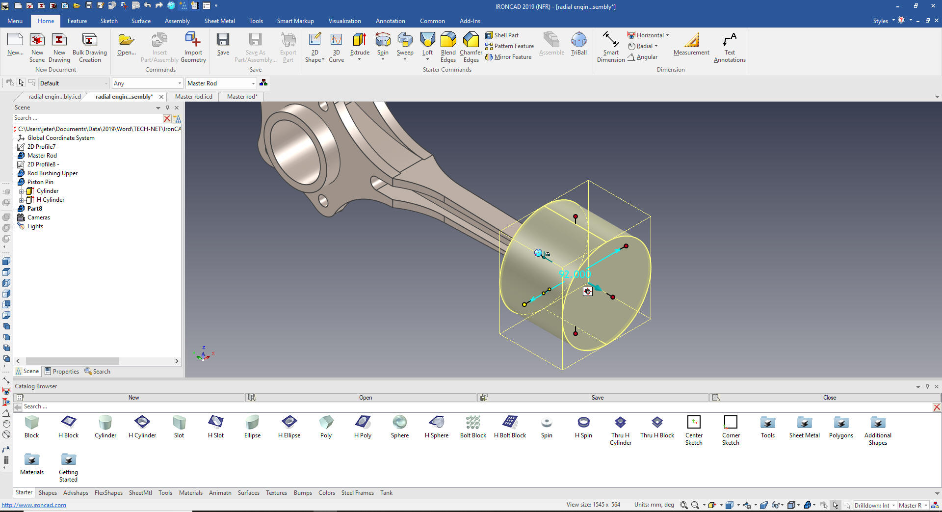 Now the next step we will drag and drop a hole cylinder to the top of the piston. I will size it and purposely leave it open to show that we can come from the top. 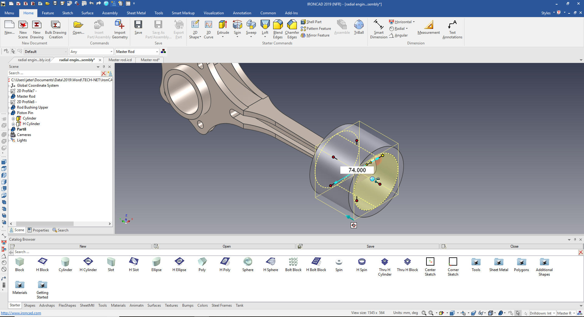 Now I will set the hole depth to 62m by edit the center handle. The level of flexibility in this design process is huge. 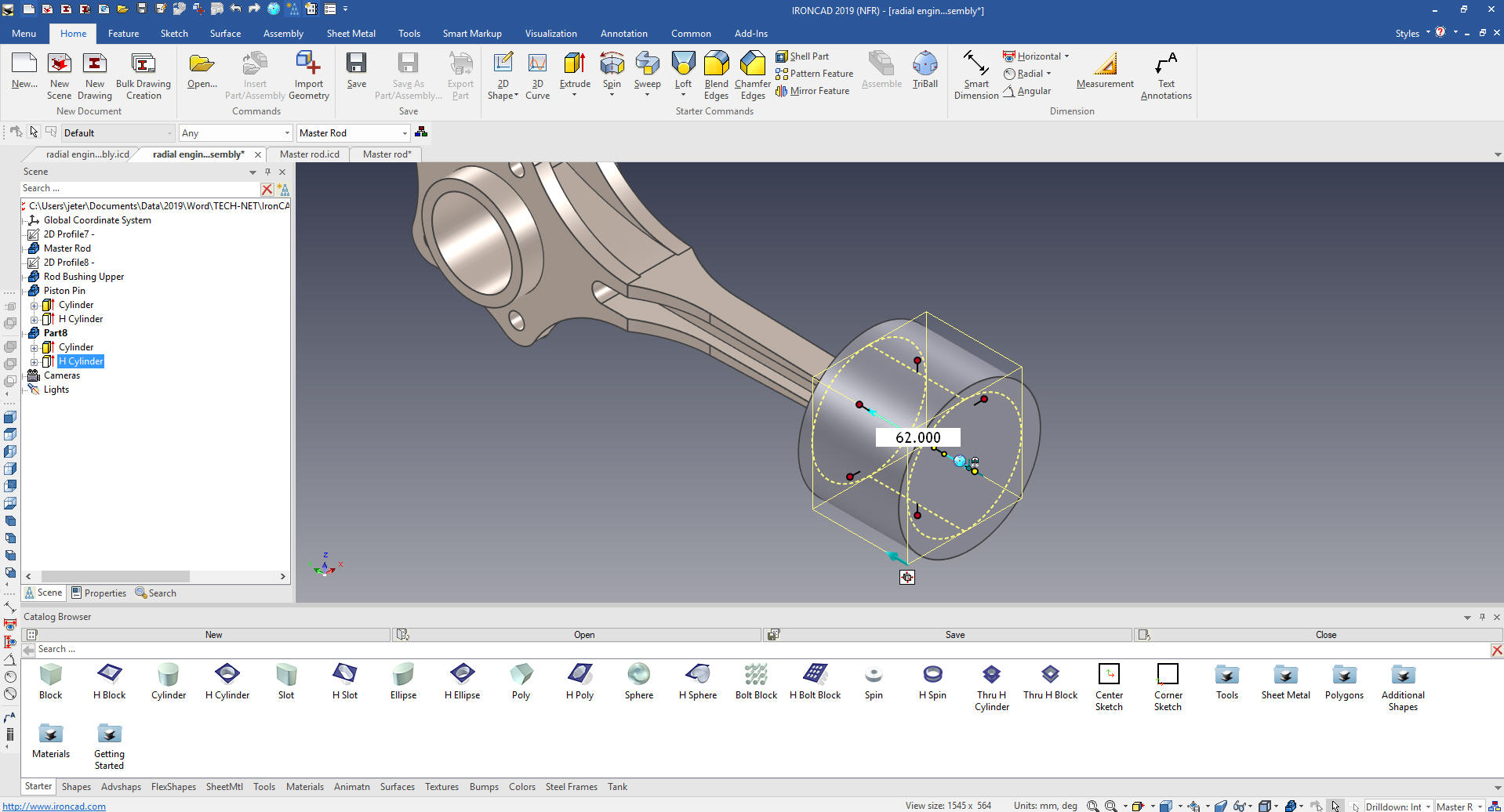 Now we will create the facecuts on the piston. I could easily do this with sketches but I want to stay with Feature Based Modeling and out of the sketching box. We we drag and drop a hole cylinder to the top center of the piston. Much of our work is dragging and dropping shapes on reference faces.  Using the Triball we rotate the hole cylinder 90 degrees and locate it 27m from the bottom with the "Edit distance from Point" 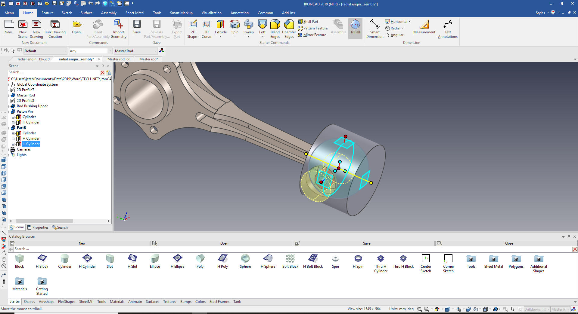 We now just size the hole cylinder. 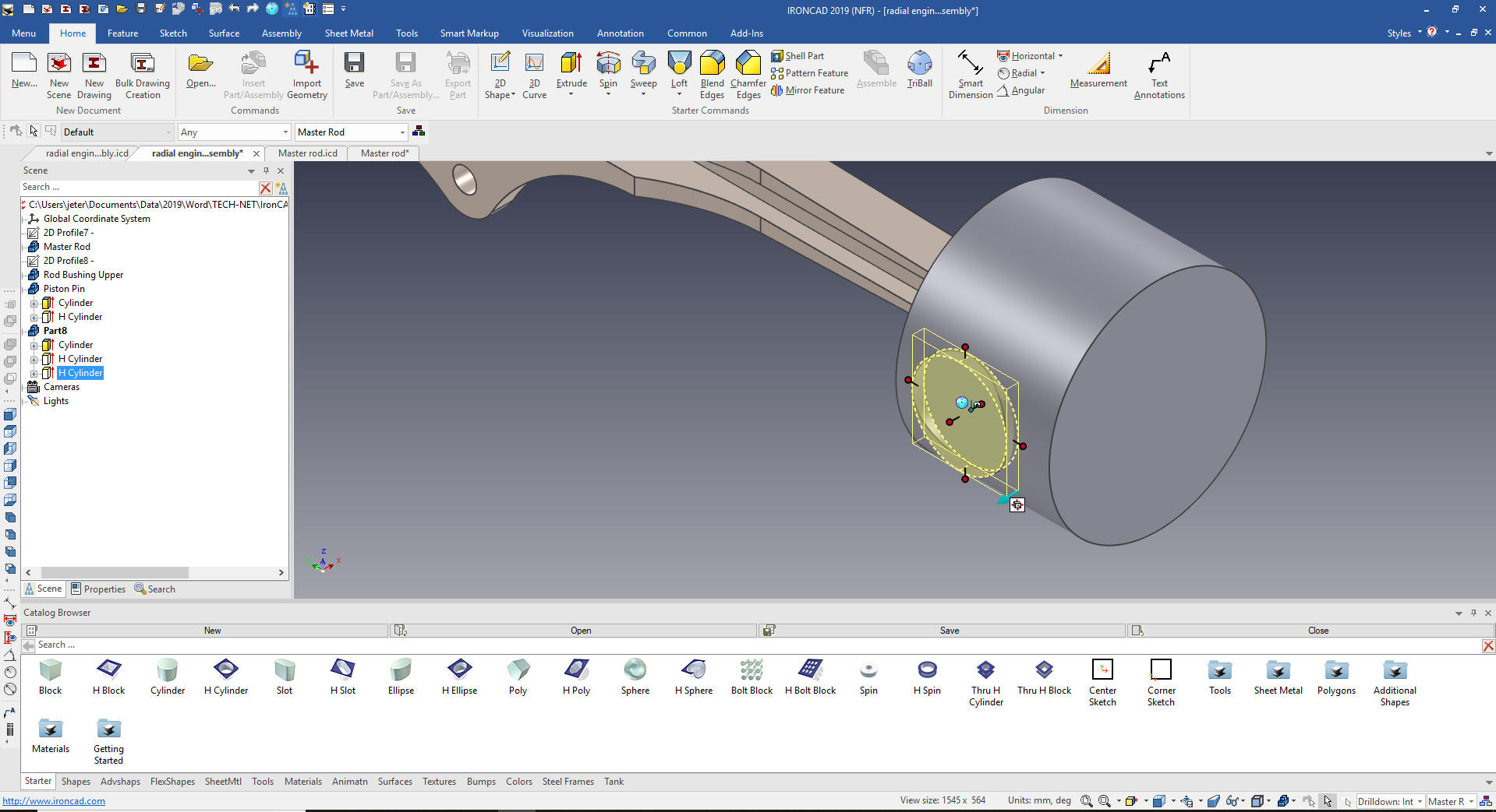 We can see the cut. 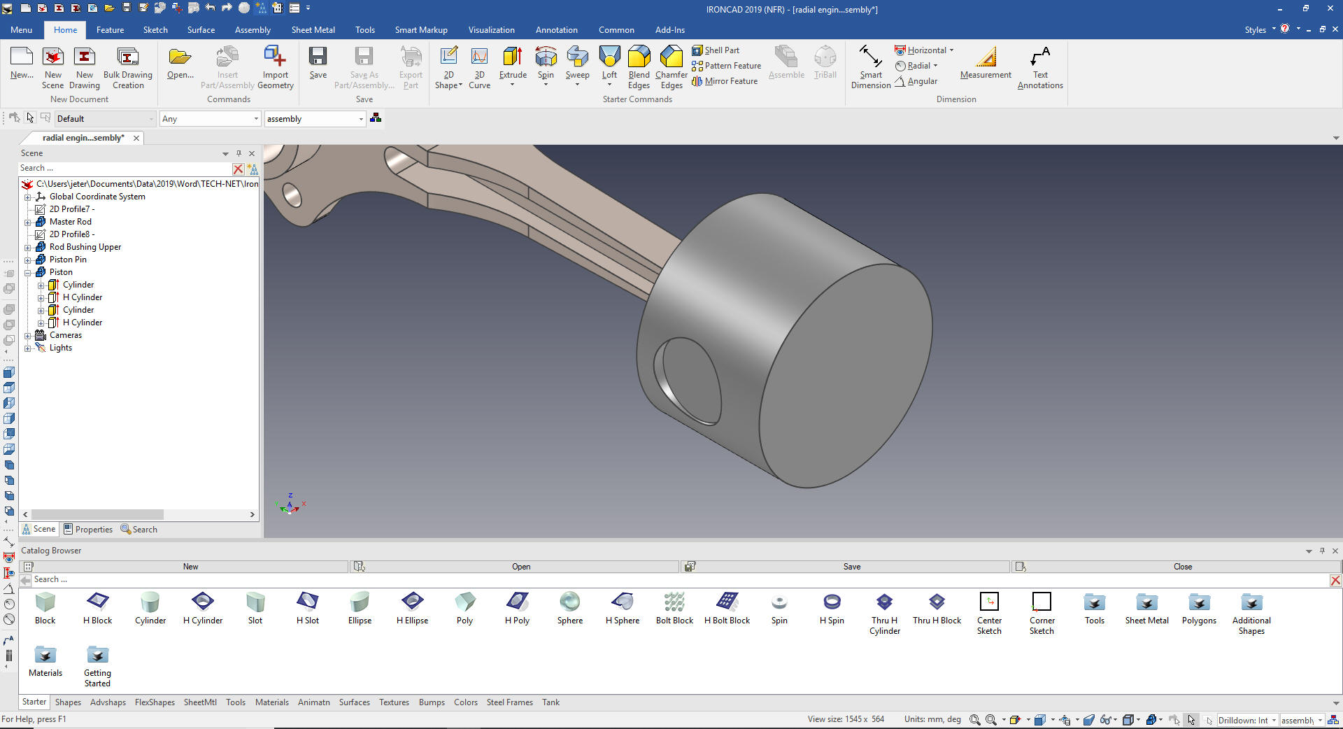 Now we will create the inside bosses. Again we drag and drop a cylinder on the new face and size it. 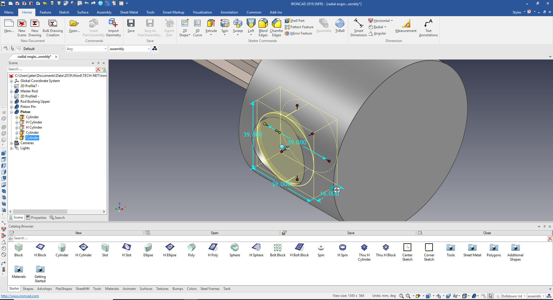 I would usually put the hole in after this mirroring step but creating it here shows how we can mirror copy link multiple features. We will just drag and drop a hole cylinder to the center and size it. Now we want to mirror the cut, the inside boss and the hole to the other side. We can select the features in the scene browser (history) or in the scene. We will select inside boss in the scene browser since it is not available in this view plus the cut. We turn on the Triball, hit the spacekey that allows us to move the Triball only and center it on the center of the top of the piston. We select the inside handle and select mirror link. 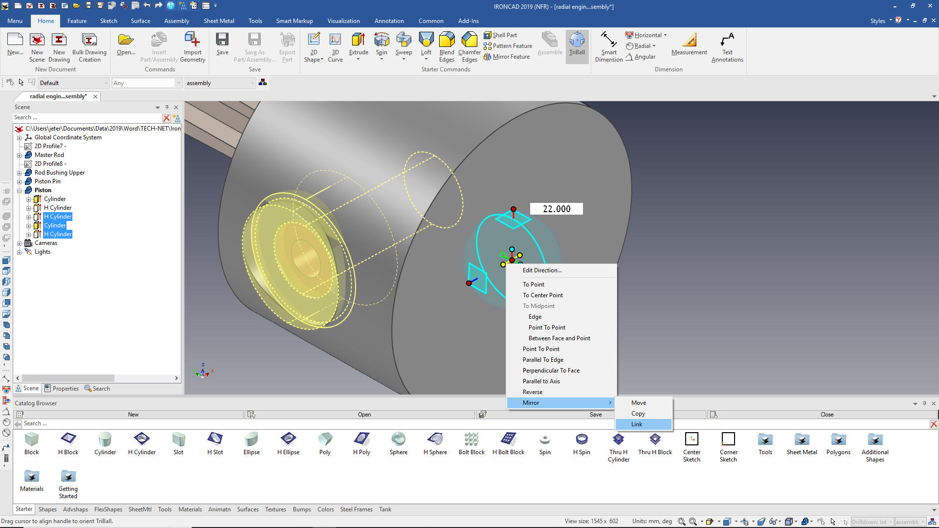 We select okay and the feature are link copied. We will hide the master rod and you can see we are done with the basic piston and components. 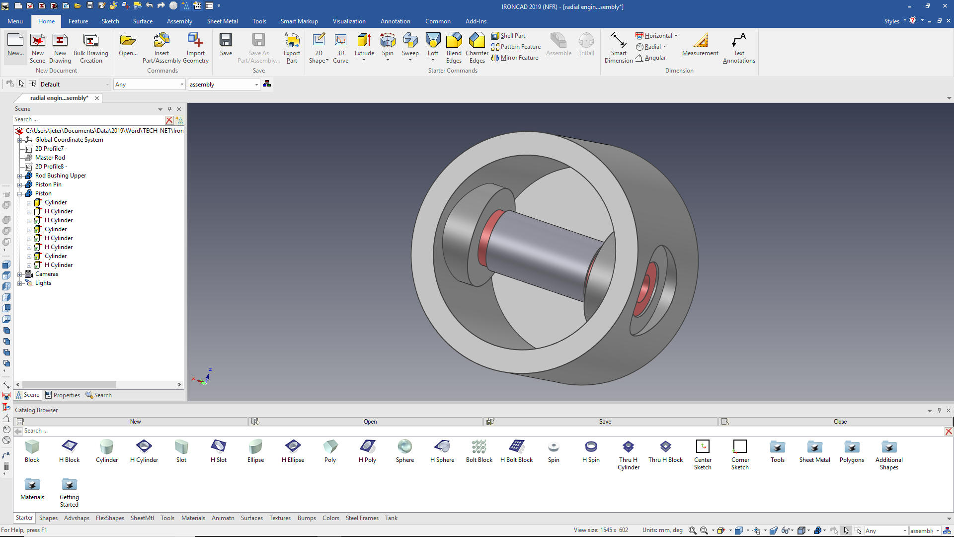 We unhide the master rod and now we can create the ring grooves. We drag and drop another hole cylinder on the top and size it. 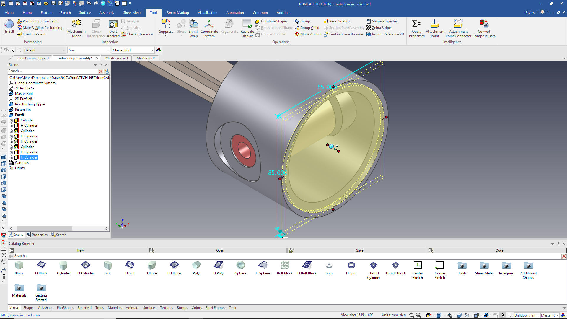 We are now going to edit an intellishape. All of the shape in the catalog are based on sketches. We are going to offset the diameter by 6m to assure we have a complete cut. 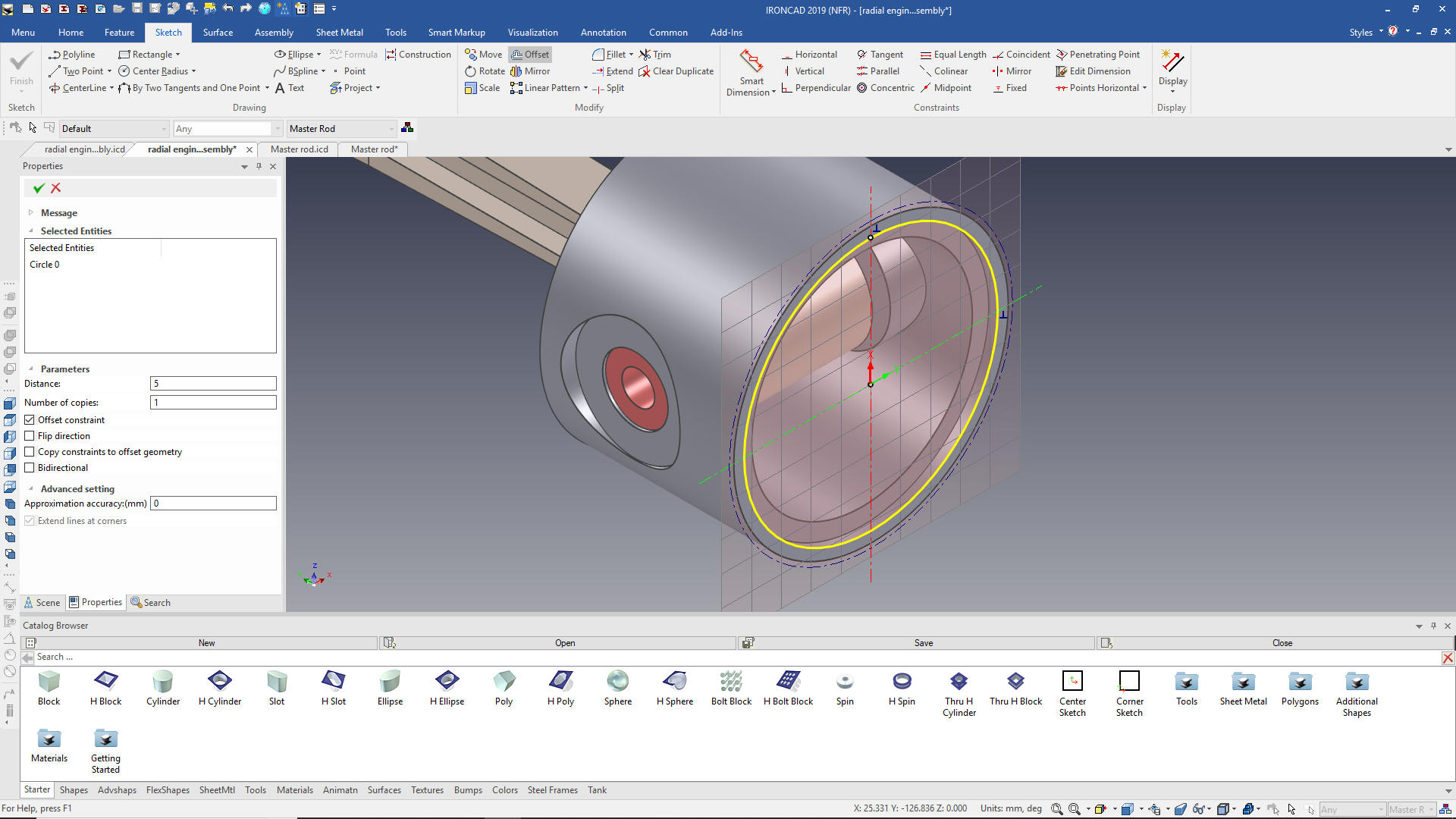 We select okay and then locate it with the Triball. 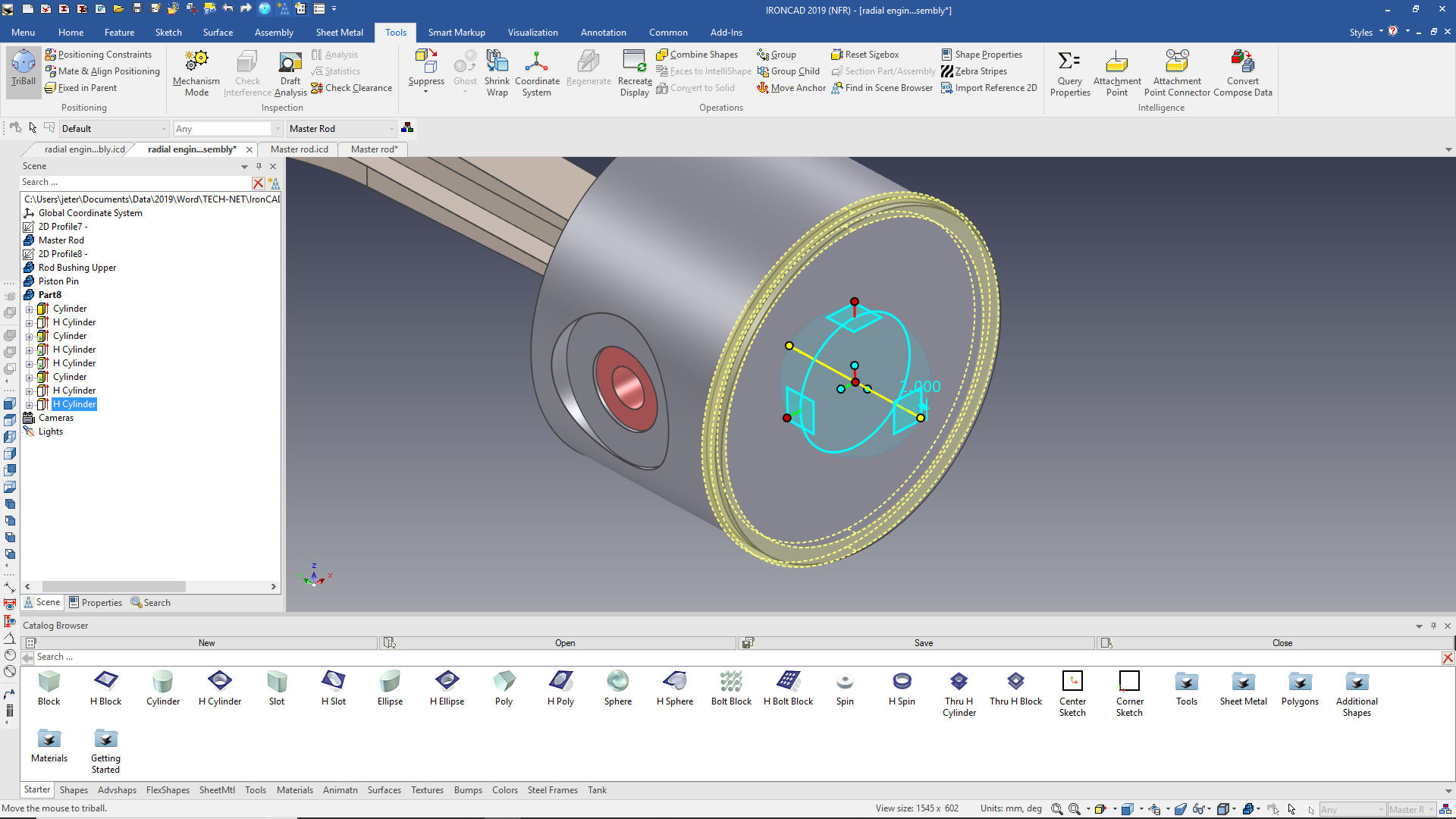 Now we copy link the three other grooves. 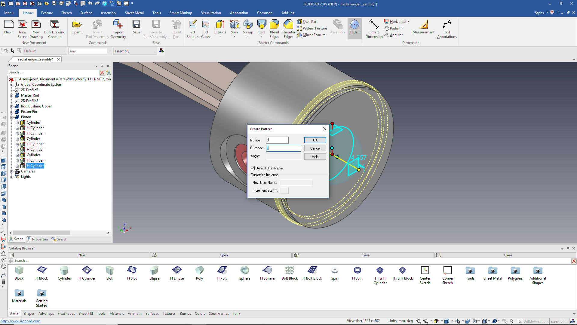 We have all of our grooves. Now when you are creating parts from a drawing sketching the grooves like the Catia presenter did may be fine, just a bit tedious and time consuming. But if you are designing you want features that can be modified. If the groove changes in size you can just edit the feature and spacing. We hope we are not training a bunch of CAD jockeys. Catia is a very expensive system used by all of the Aircraft companies. We need CAD engineers that know how to optimize the design. For the only constant in engineering is change. 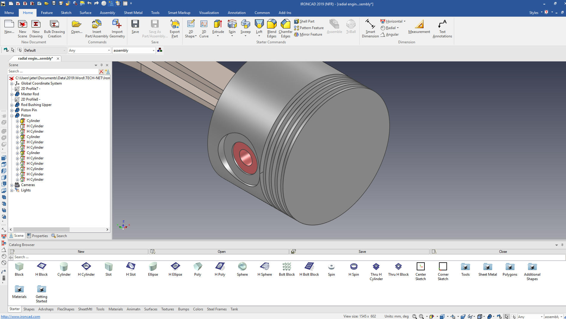 We now select the bottom groove and with the Triball locate it to the bottom. This time we will copy it, since we have to resize it. 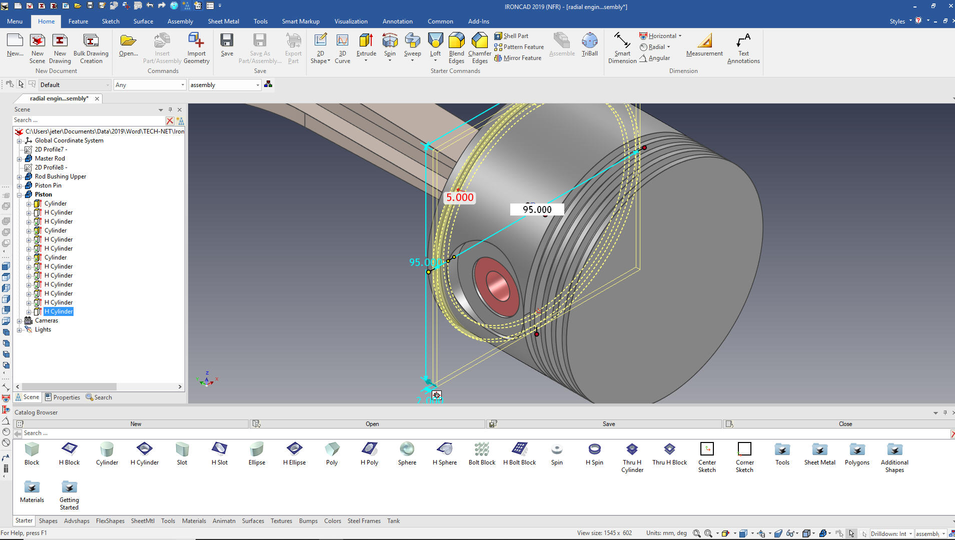 Now for the dome we use the spin wizard and create the sketch. Again we us no constraints. 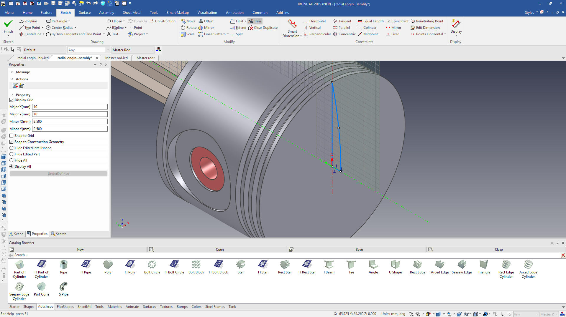 We select okay and we are done with the piston. We rename it in the scene browser and change the color. Piston Pin Plug We drag and drop a cylinder to the center of the hole in the piston pin using the right mouse button to create a new part. 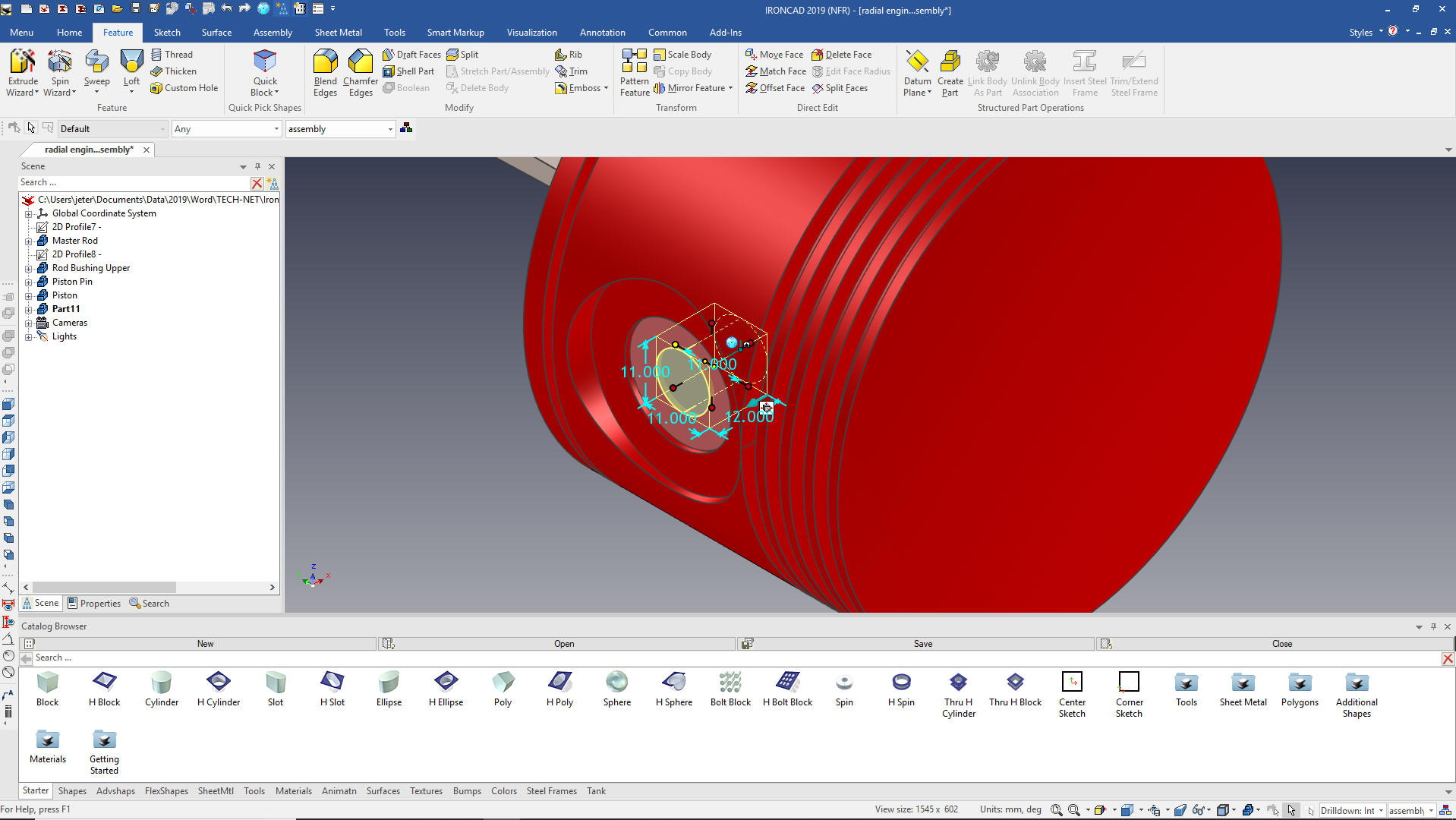 Now we do it again to the center of the new cylinder but this time with the left mouse button to make it part of the cylinder, size it. 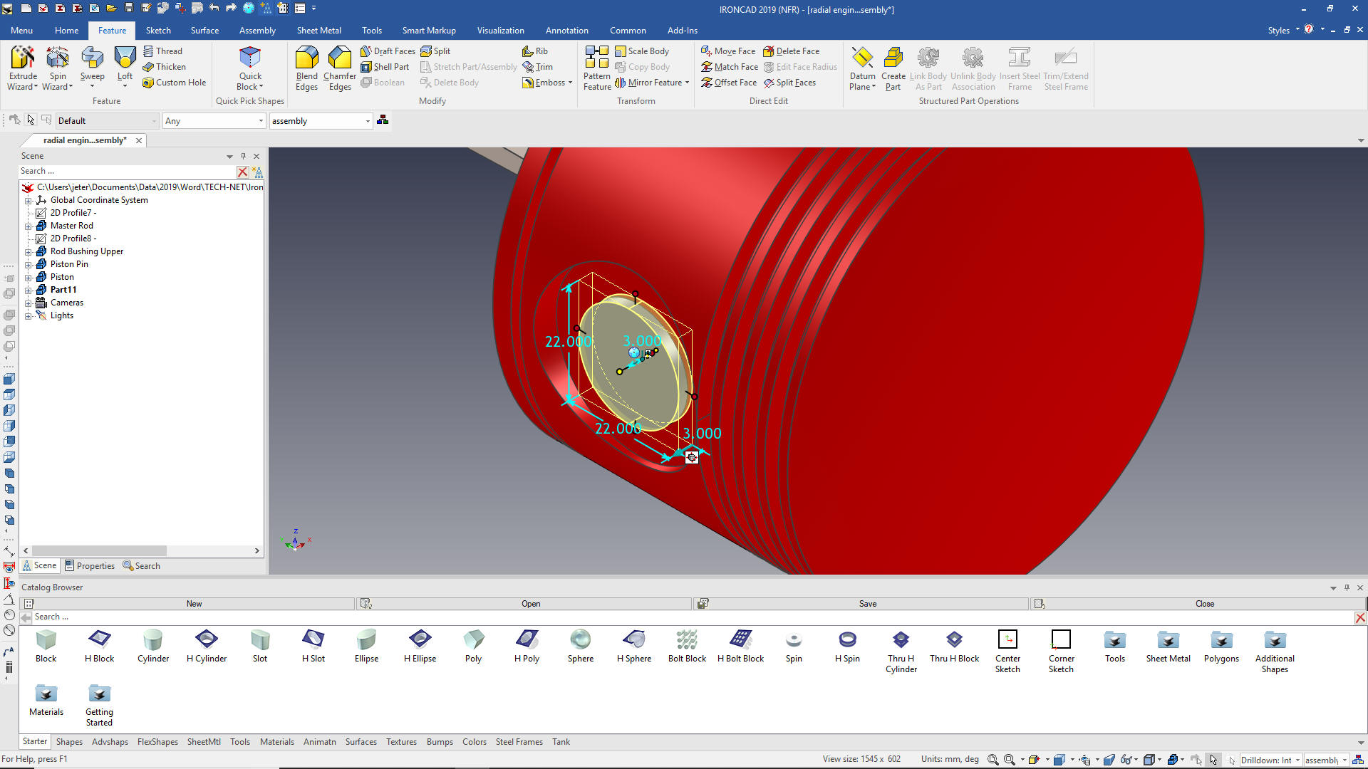 We add the blend, rename the part and change the color and using the Triball mirror link as we did above, and we are done with the piston and all of its components. Linking part and sub-assemblies defines the quantity when creating the parts list. 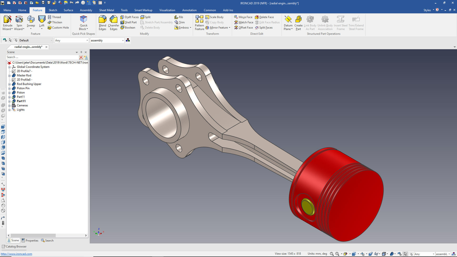 Piston Ring Now for the piston ring. We drag and drop a cylinder on the center of the top of the piston so we are in the same orientation as the grooves. We size it to the OD. 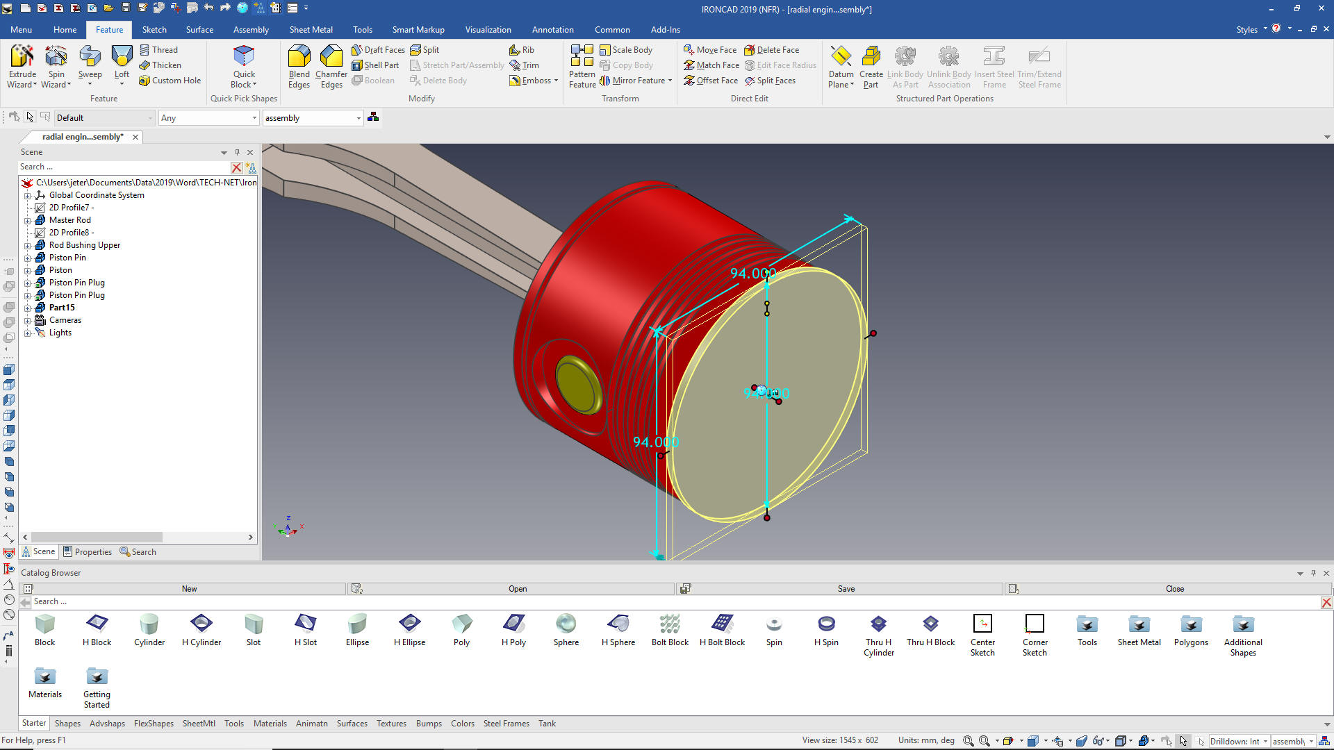 We now select edit cross section and create the offset of 4m. 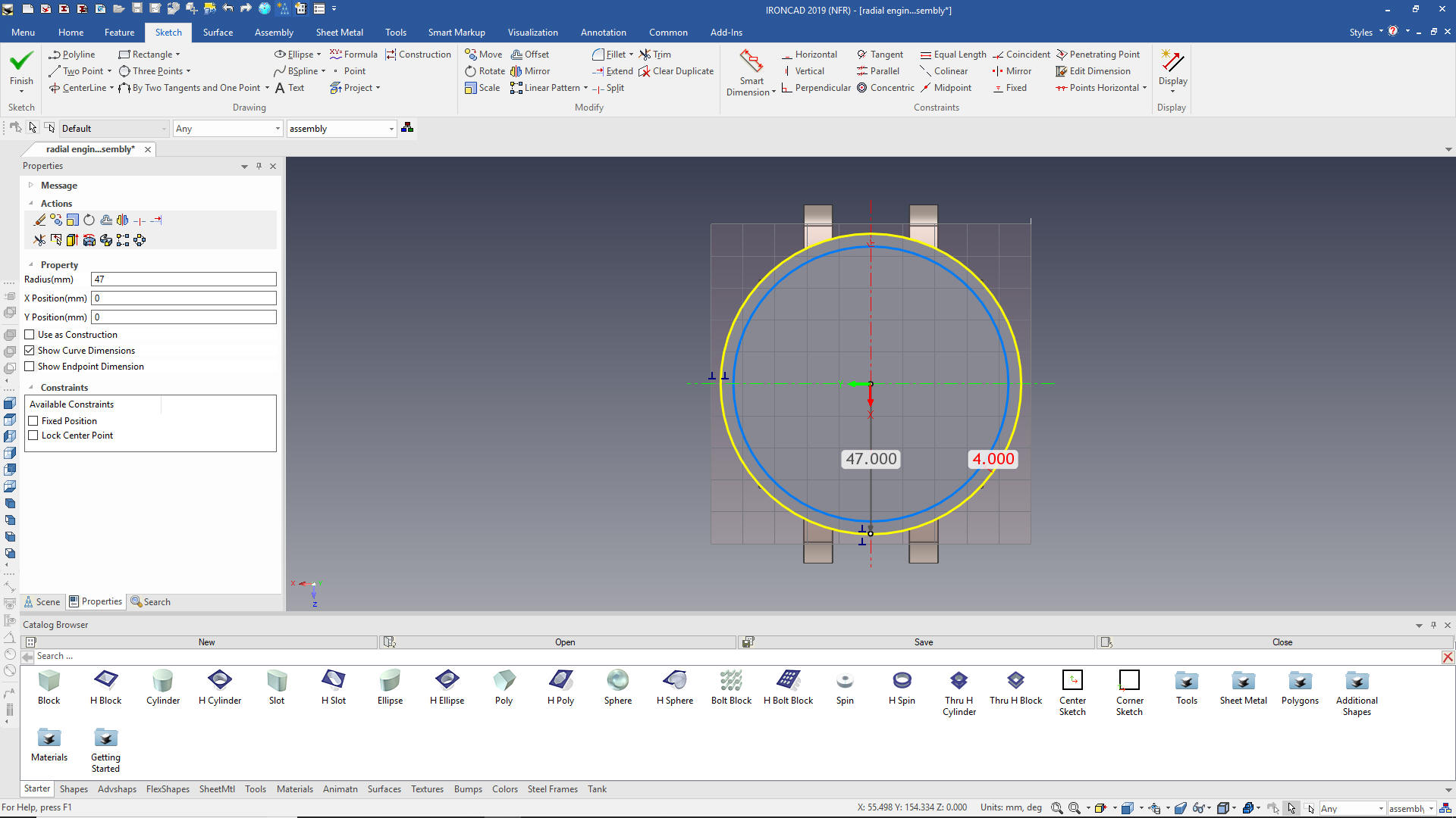 We now need to create the cut in the ring. Using the extrude wizard we create a sketch plane locate it and create the sketch. 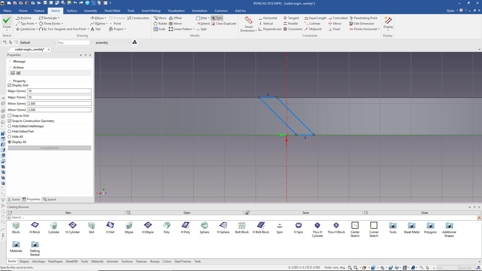 We pull the extrusion into place and we are done with the ring. 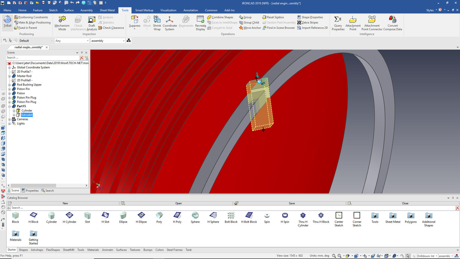 We move the ring into place. 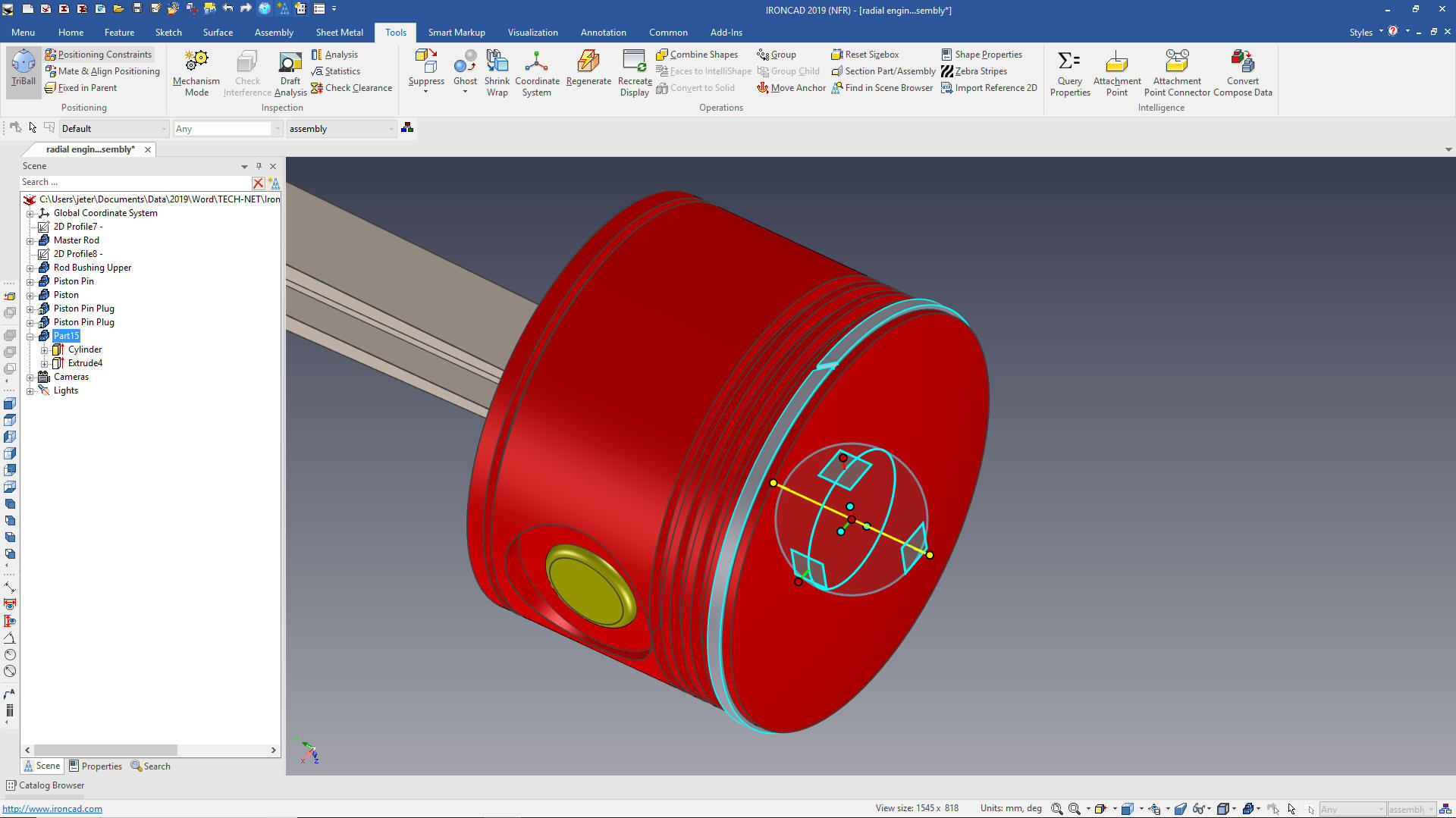 We change the color and copy link the other three rings. The purple highlights indicate we have 4 linked rings. 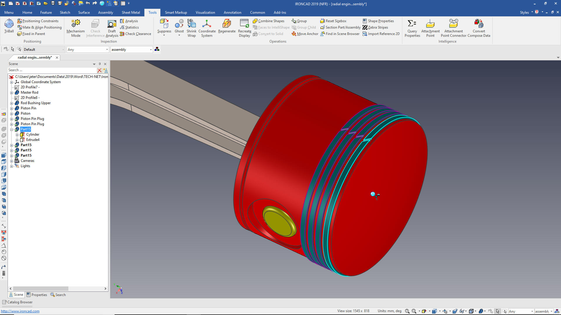 Articulated rod First we scrutinize the design and realize it is based on a square rod. We drag and drop a block on the face of the master rod using the right mouse button creating a new part. We size it and locate it, we have to rotate it 35 degrees. 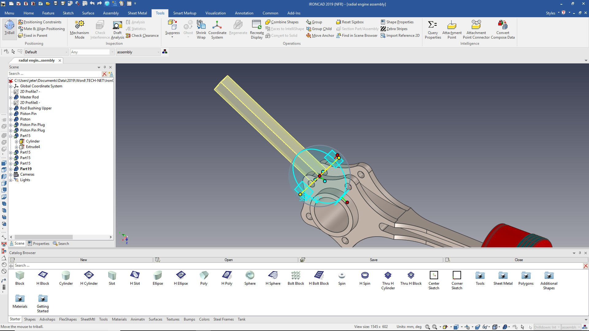 We now drag and drop a cylinder on the face of the square rod, size it, locate it and the drag and drop a hole cylinder the center face of the cylinder and size it. We are doing some incredible in context design. 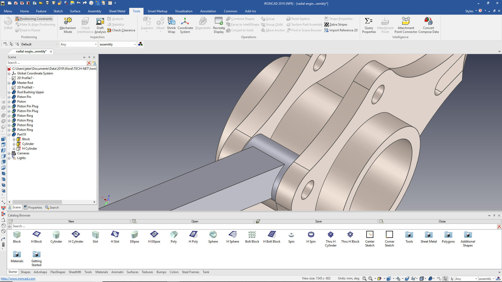 Now for the other end. If you are following closely you probably know what I going to do. Yes, drag and drop a cylinder to the mid-point of the rod and size it. Then drag and drop a hole cylinder on center an size it. 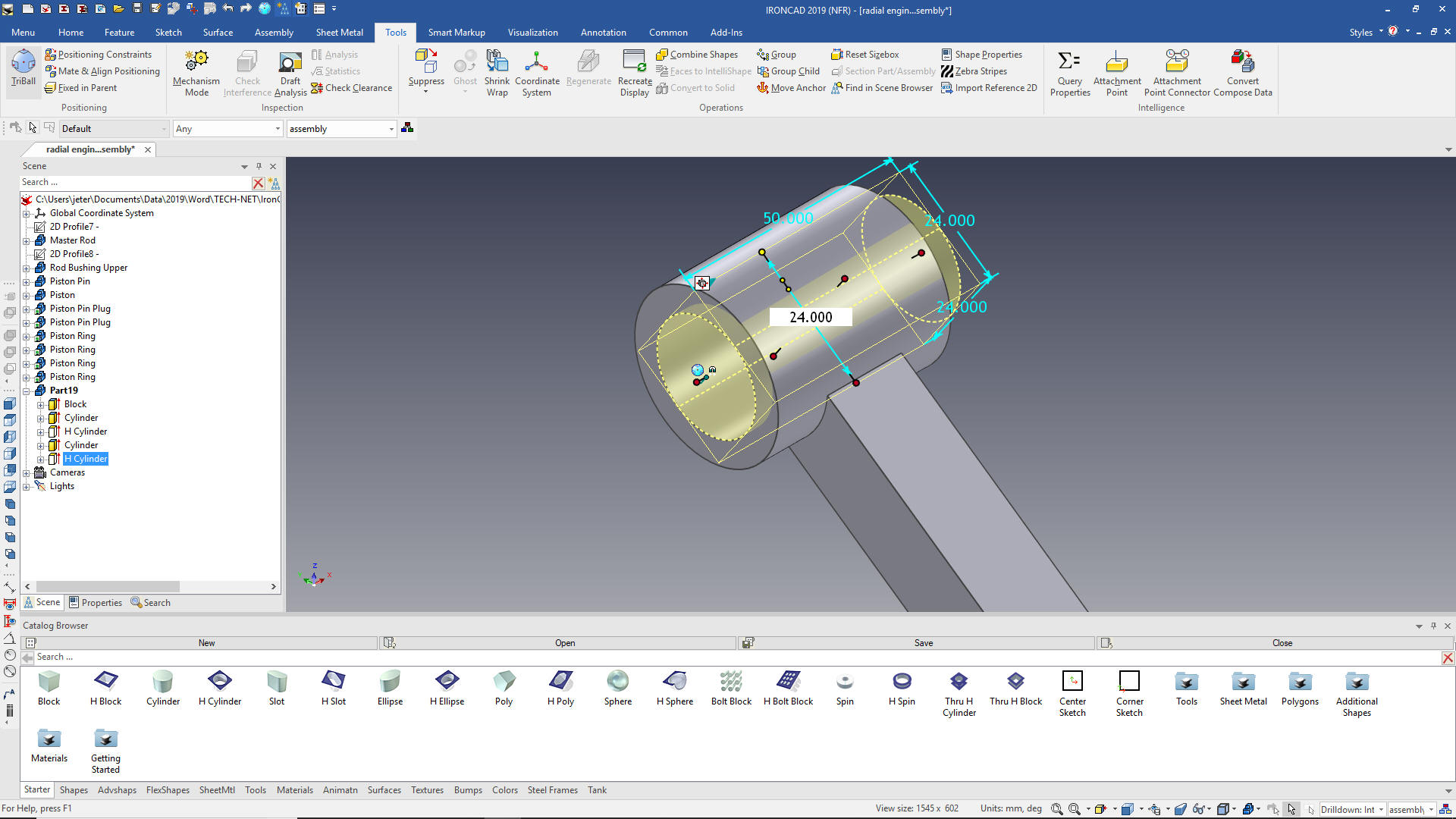 Now for the slot. We drag and drop a hole slot on to the face of the rod, yes, locate with the TriBall and size it. 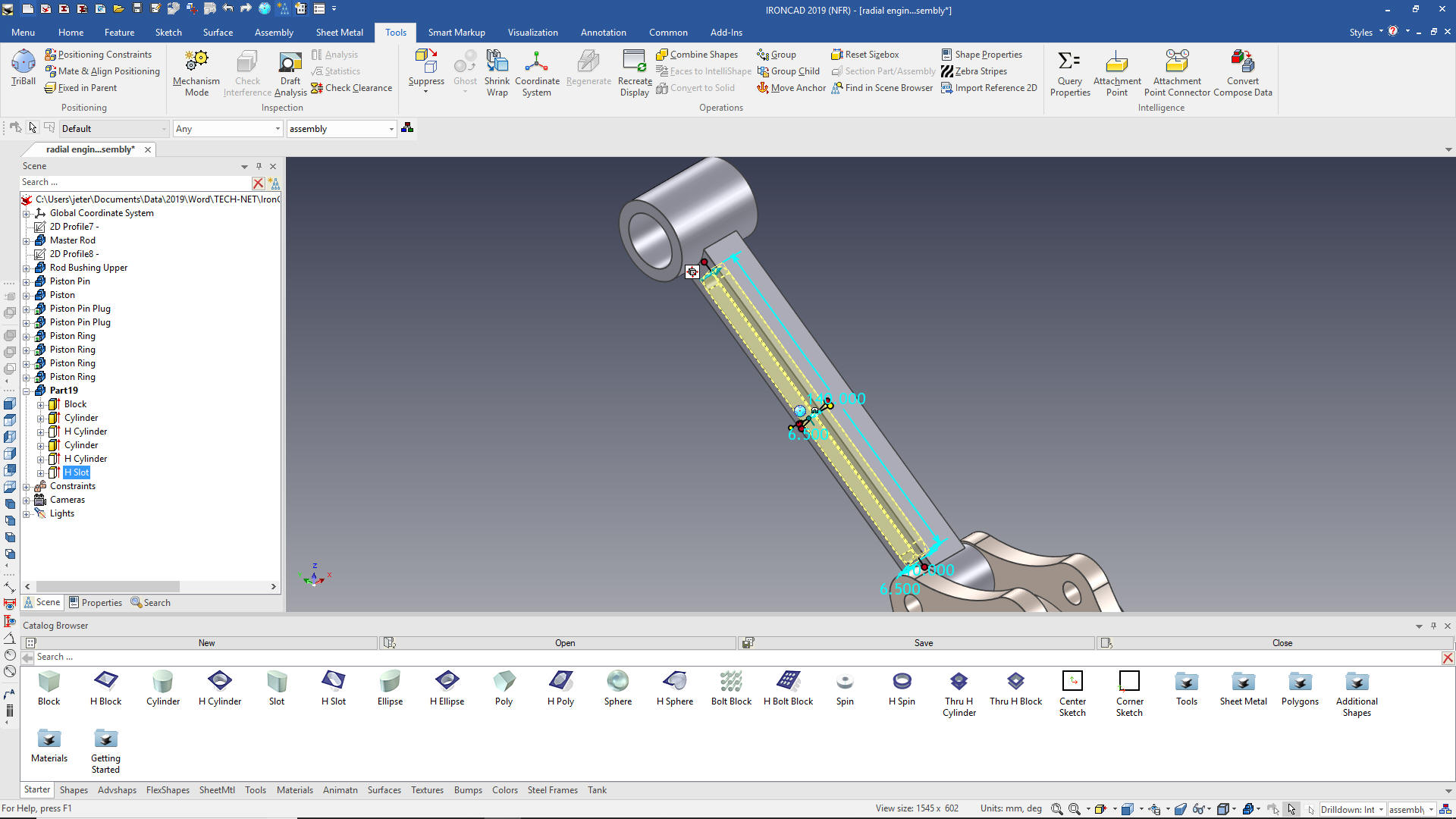 Now mirror link the slot and add the blends and we are done with articulated rod. We rename the part and change the color. Rod Bushing Lower Now we hide everything but the rod to create the rod bushing lower. We drag and drop a cylinder to the center of the rod end and size it. 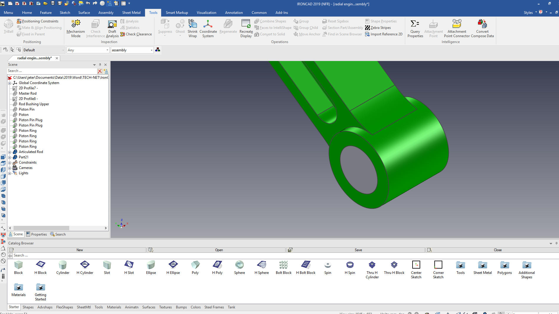 We drag and drop a hole cylinder on to the center of the new cylinder and size it. We rename the part and change the color. 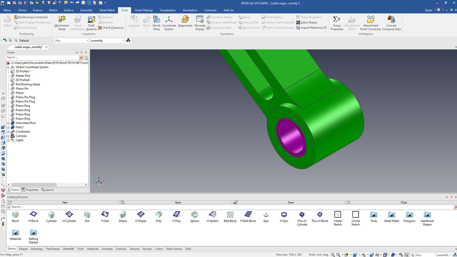 We now need to create some assemblies and configurations. I can't believe that amount of time it takes to make assemblies and insert them into the assembly. Again, I keep thinking of the thousands of engineers working with Catia in the major aircraft companies and a couple of automotive manufacturers wasting thousands of hours of designing separate parts and sub-assemblies. We will now create the assemblies. 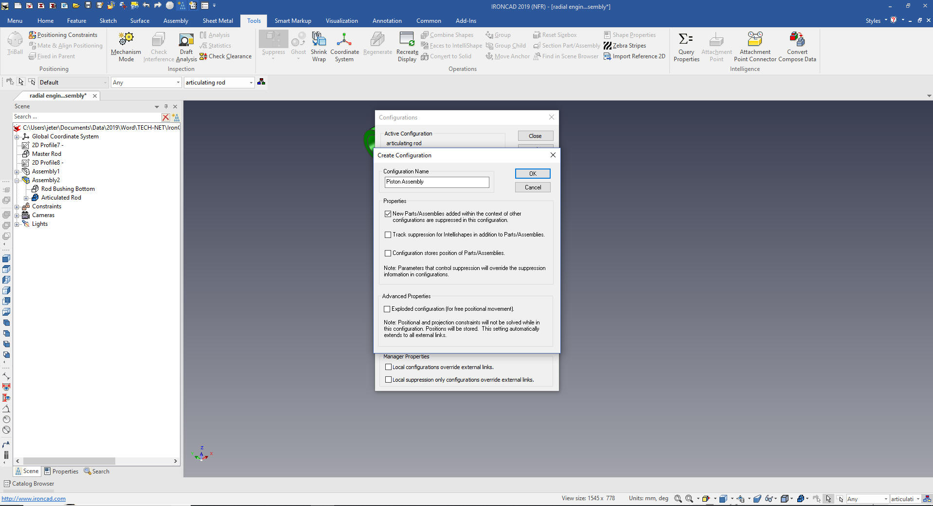 Piston Assembly Assemblies are nothing more than selecting the components and selecting assemble. 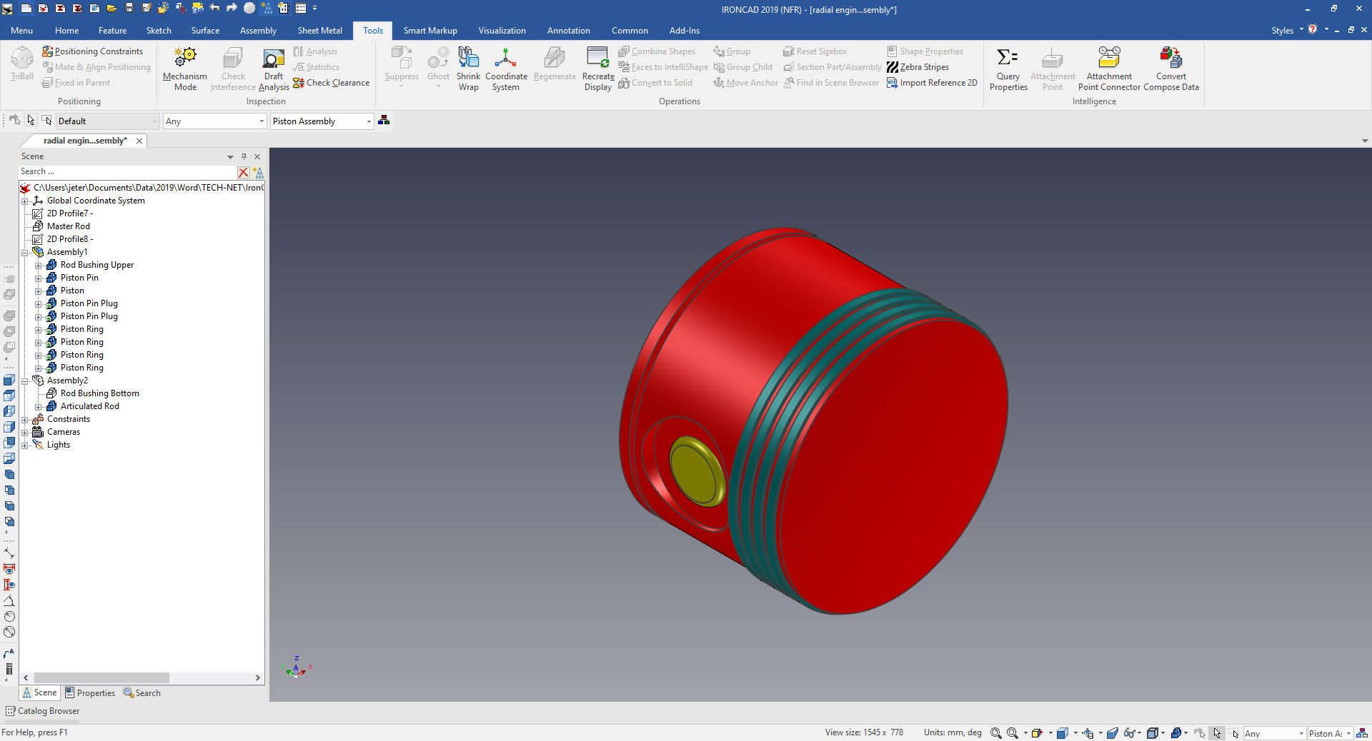 Articulate Rod Assembly (I combined this with the Piston/Articulated Rod Assembly thereby eliminating one of the sub-assemblies) 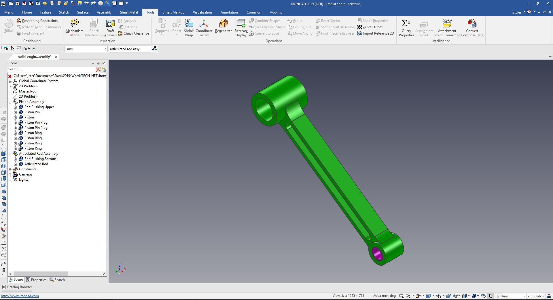 We already have a master rod configuration. We will now create the configuration for each of the parts for creating AIDs (drawings). We only include one part. Piston/Master Rod Assembly 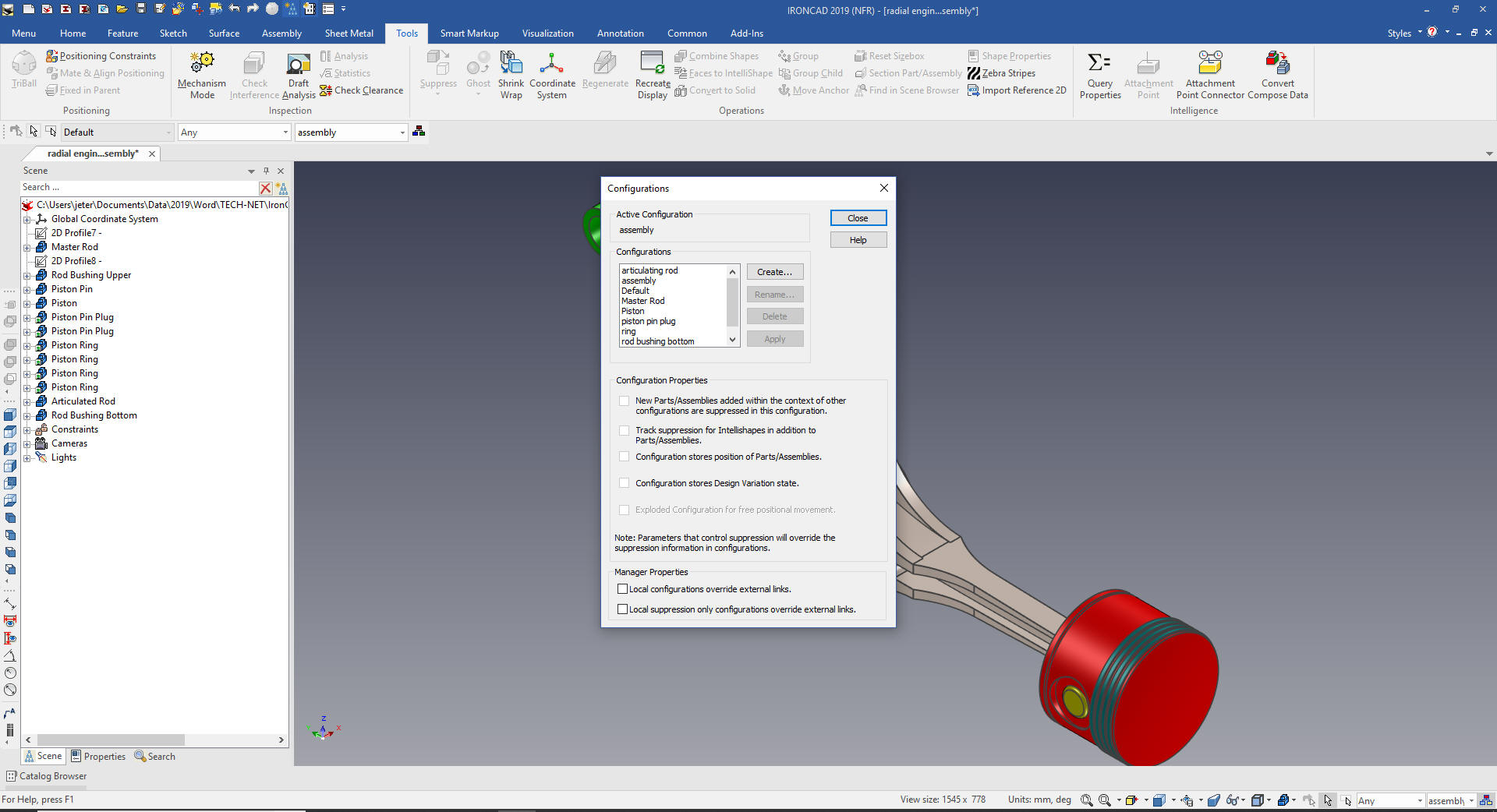 Piston/Articulated Rod Assembly We copy link a piston assembly to the end of the articulated rod. I have locked the plane of Triball so I can just pick the center of the piston and center of the rod end. 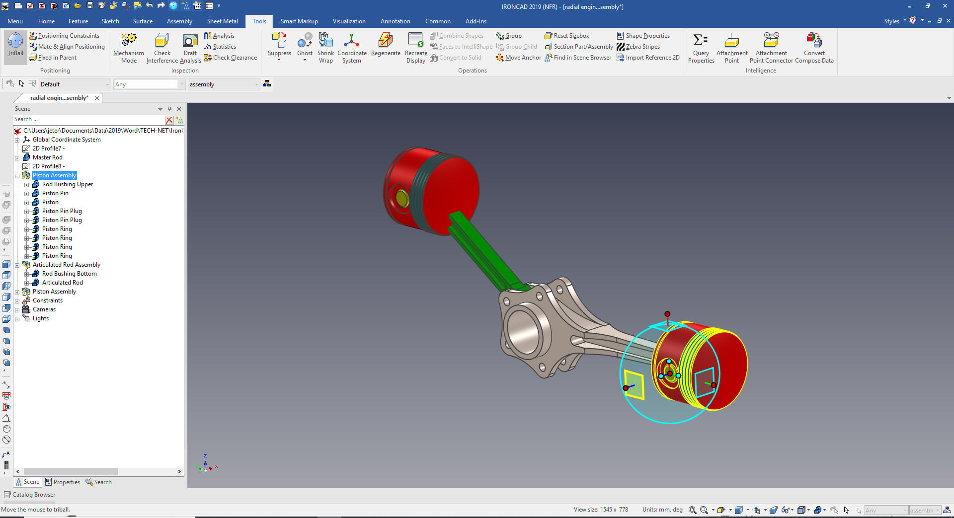 The Triball is a very sophisticate device. You are always learning something new about it. We rotate the Piston assembly into place. We will now make a Piston/Articulated Rod assembly by selecting the piston assembly and rod. We create a Piston/Articulated Rod configuration. Manipulating the components is easy with the TriBall. Its flexibility truly shows no bounds. 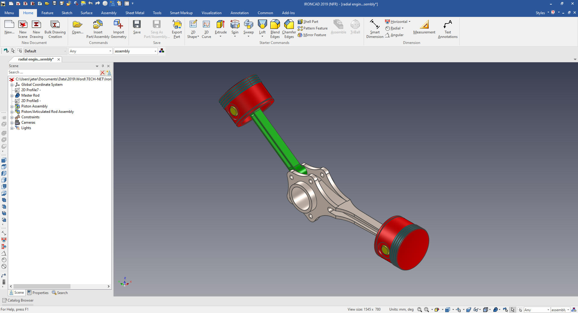 TOP ASSEMBLY We will now copy link the other Piston/Articulated Rod Assemblies. We move the TriBall to the center of the lower attach point and we lock the TriBall to a plane, notice the highlighted plane indicator. 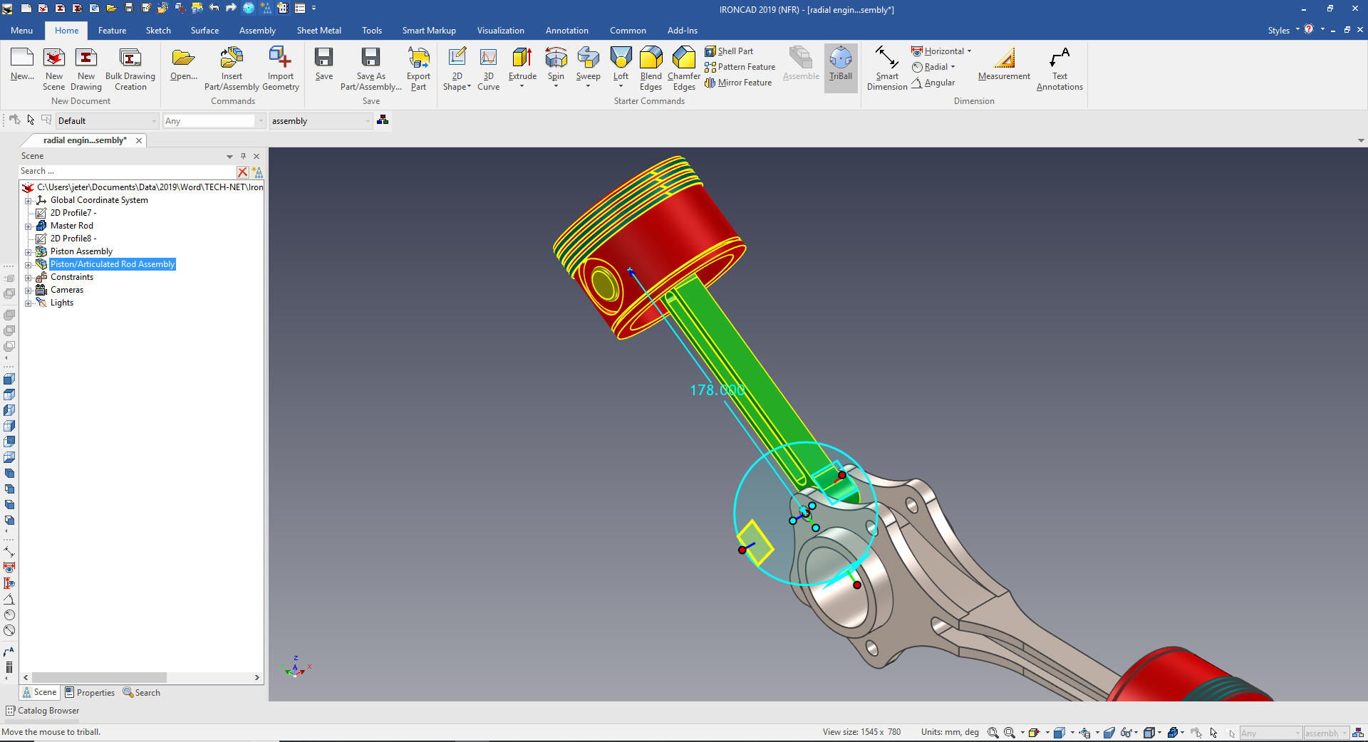 We just select the center an copy link them into place. The purple highlights indicate all of these assemblies are linked. 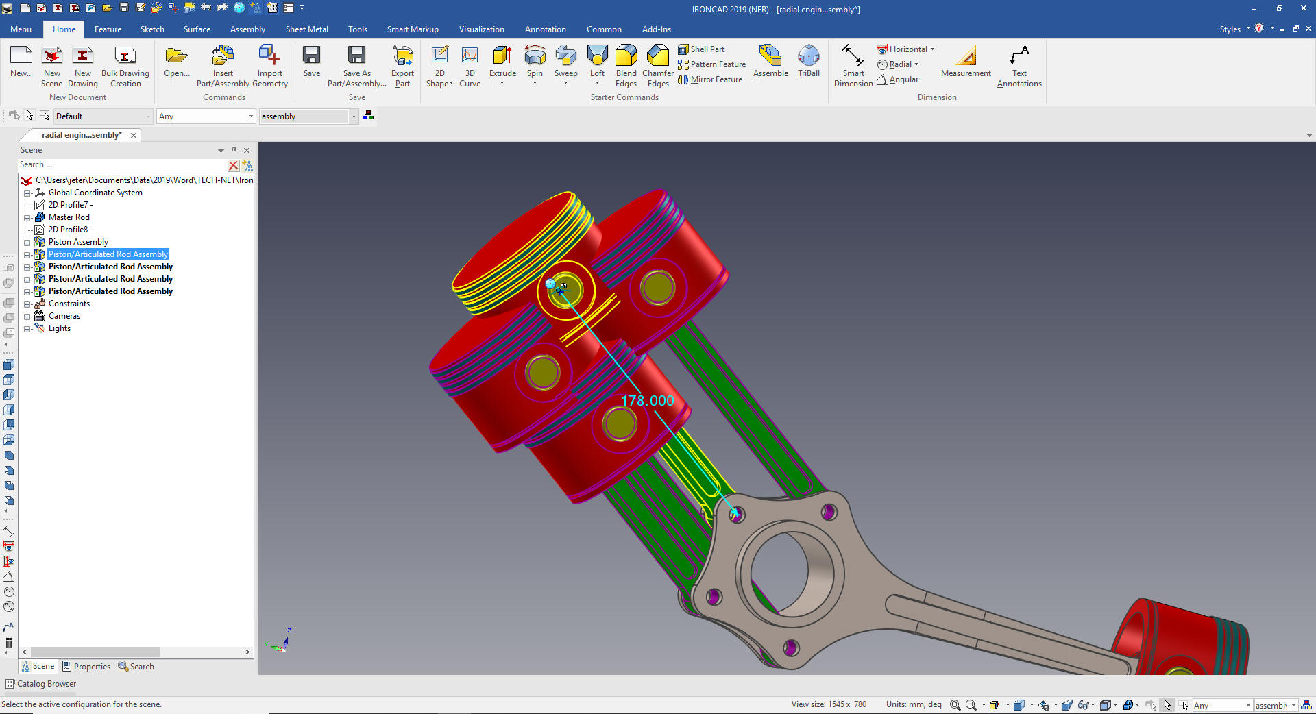 We will now rotate the assemblies into place using this diagram.
We are done with the basic assembly we need to add the link pin and master bushing 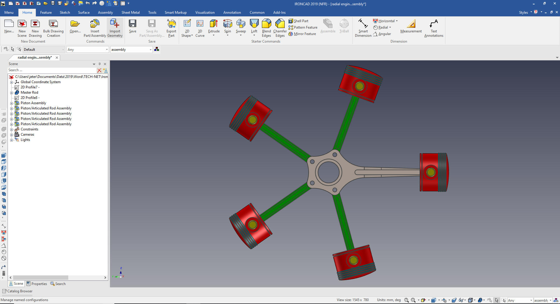 I drag and drop a cylinder to the center of the connecting hole. I want so show that IronCAD recognized that the holes were linked and asked if we wanted the cylinder added the other holes. 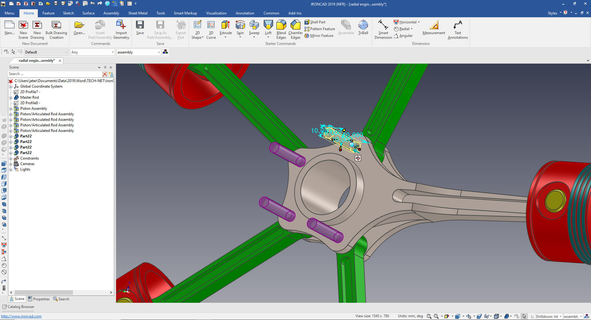 We size the shaft and drag and drop a cylinder on the top center. Again IronCAD recognizes the other linked shapes. We just rename the part and change the color which affects the other pins. 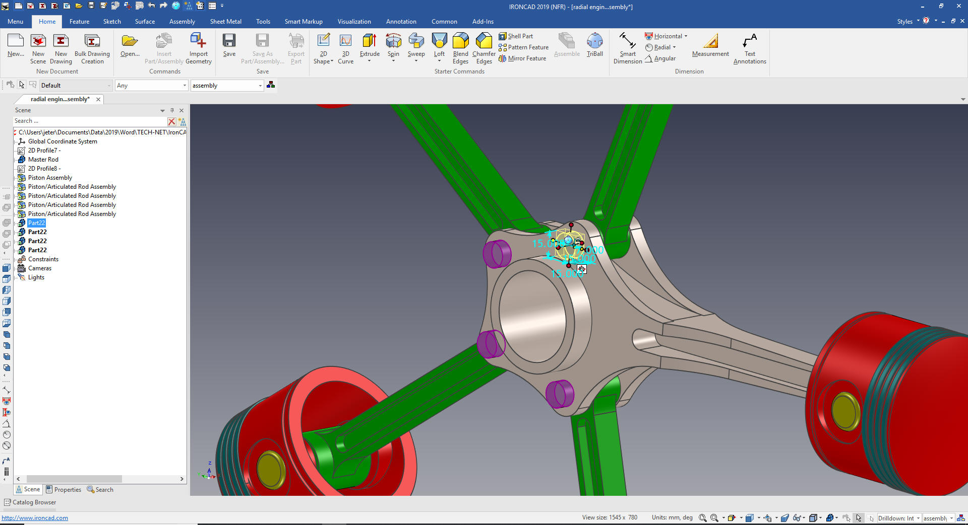 Now create the main bushing. I will just drag and drop the cylinder to the center and another hole cylinder to that center and size them and change the color. We are done with the assembly! This is by far the most revealing presentation showing the weakness of Catia 5 and all of the other Pro/e (Creo) design paradigm. 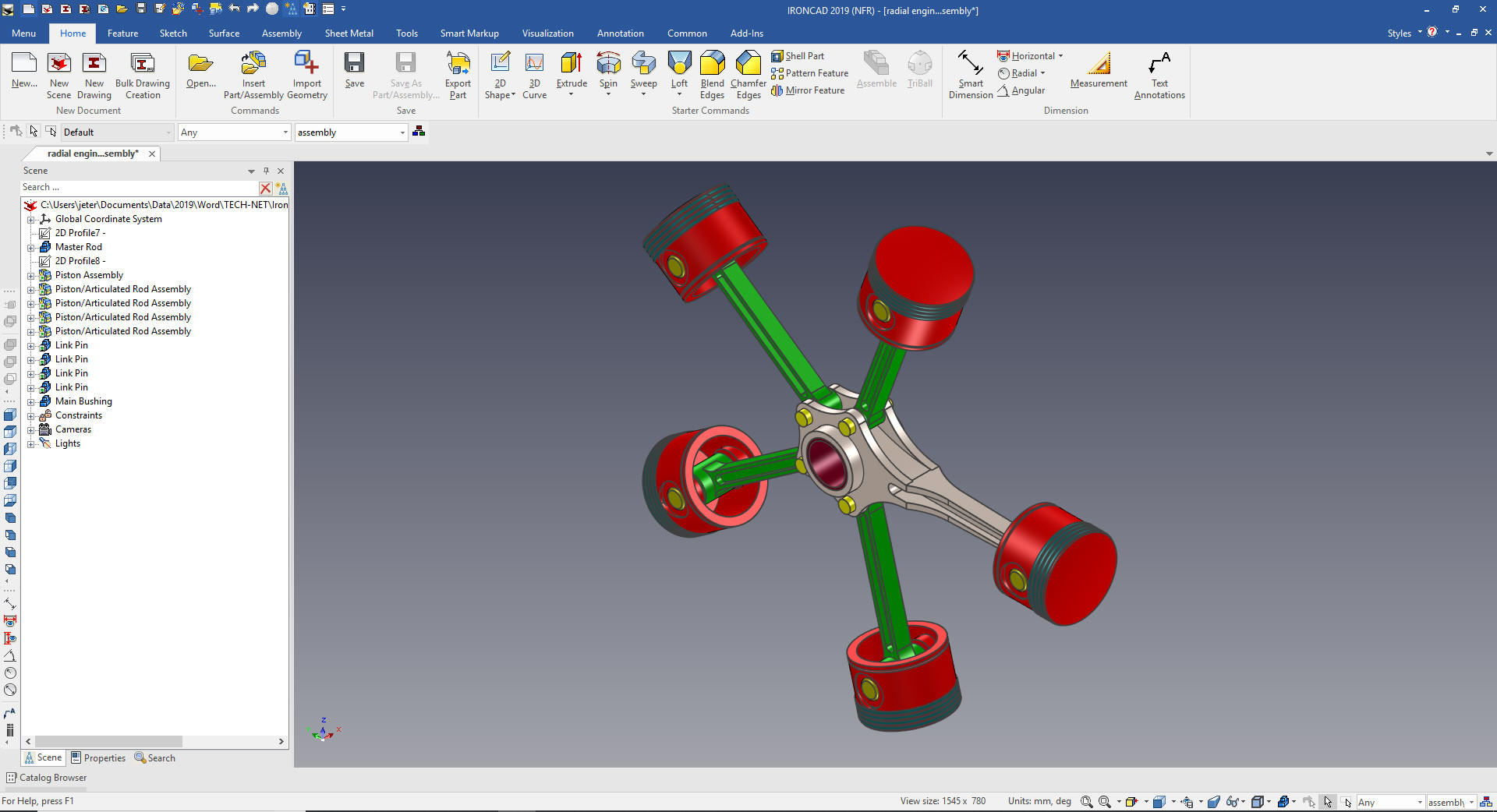 Here is our scene browser (History Tree) with all of the parts and sub-assemblies defined. The small arrows indicate that it is a linked model. Imagine the problems with PDM this would solve. Yes, you can have external parts, even located in a set of task specific catalogs available to all designers. You even have the sketches necessary for the individual parts, which were only used with the Master Rod. 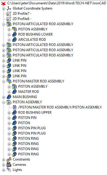 IronCAD has a separate documentation module. Since IronCAD is a Single Model Design Environment we can have complete projects in two files. But if you have the job of converting drawings to 3D you have to create a drawing to check to see it the model is correct. All You Wanted to Know About Drawing to 3D Conversions Here are the AIDs (drawings). How would you do these parts and assemblies? This format is called the detailed assembly. We could have easily just given each AID a individual AID number. IronCAD separates its parts/sub-assemblies for AIDs (drawings) by configurations as I have referenced before. We detail the assembly and we have a configuration called "assembly" and we set it and then go to the documentation module to create our AID (drawing).  We now detail the Piston  Piston Ring  Bushings  Pins  Articulated Rod  Articulated Rod Assembly  Master Rod Assembly  Piston Assembly  Master Rod  Piston Placement  It is very important that you look into how you or your engineers are creating the parts. Streamline Sketching and Feature Based Modeling is easy to learn and implement. It, alone, will increase productivity 10X. Now, IronCAD with its unique integrated history/direct edit functionality can increase your productivity another 5X or more with changes! Again, time is money in engineering. More on Streamline Sketching and Feature Based Modeling. 3D CAD Modeling Techniques To experience this increased level of productivity, please download IronCAD for a 30 day evaluation. Legacy data is no problem, IronCAD can read the native files of all of the popular programs. IronCAD is a great replacement for the subscription only Autodesk and PTC products. Give me a call if you have any questions. I can set up a skype or gotomeeting to show this part or answer any of your questions on the operation of IronCAD. It truly is the very best conceptual 3D CAD system. |