3D Modeling is the basis for our
engineering. That is the only place where productivity is paramount.
You can have all the PLM/MBE gurus debating data management, but it
does not add one smidgeon of productivity to the design process.
Top down or In-Context modeling is the most productive
feature of 3D CAD. Most systems tout this but each part is still and
external part. We are talking about a single model of multi-object
design environment. Both of the systems we represent offer this as
the "normal" design process. Thereby increasing your productivity 20
to 30%.
In these exercises I not only focus on modeling techniques, but
also on much more productive systems to do our designs. I hope you
enjoy them and learn something. If you are in management, understand
that all 3D CAD systems are not the same. Cutting your engineering
costs is very simple. Even your legacy data is not a problem. Please
feel free to give me a call. There are millions of man hours wasted
every day with poor modeling techniques and dated 3D CAD
systems that cost a fortune. Productive 3D CAD systems do not have
to be expensive.
Joe Brouwer
206-842-0360
I am doing the below assembly for
an exercise showing my modeling techniques and, of course, my 3D CAD
solutions.
3D CAD Modeling Techniques
When I introduce IronCAD's very
flexible design paradigm I have a hard time to get the Pro/e clone
users, like Solidworks and other programs to understand the drag and
drop design paradigm.
I saw the
following video challenges on linkedin and thought I would give it a
try on IronCAD. This will give you an idea how different
and flexible IronCAD is compared to the conventional Pro/e clone and
to the not so conventional Fusion 360.
IRONCAD vs Fusion 360
These exercises started out to show the benefits of IronCAD over Fusion 360, but
quickly turned into a study of modeling techniques. Take a look at all of
them, they will open your eyes to a much different and more productive way of
modeling. It really has more to do with modeling technique than it has to do
with the 3D CAD systems. I have found that I do 3D modeling as compared to
the conventional 2D sketching. Of course, having a more productive 3D CAD
system doesn't hurt.
These exercises were incredibly
popular and I thought I would follow up by showing more examples of
this 3D modeling technique.
We will be doing a
couple of parts each weekend in both IronCAD and ZW3D. I hope you
enjoy these exercises and hopefully they may lead to increasing your
productivity.
Please feel free to review the
prior lessons:
3D Modeling Techniques IronCAD Lesson One
3D Modeling Techniques IronCAD Lesson Two
3D Modeling Techniques IronCAD Lesson
Three
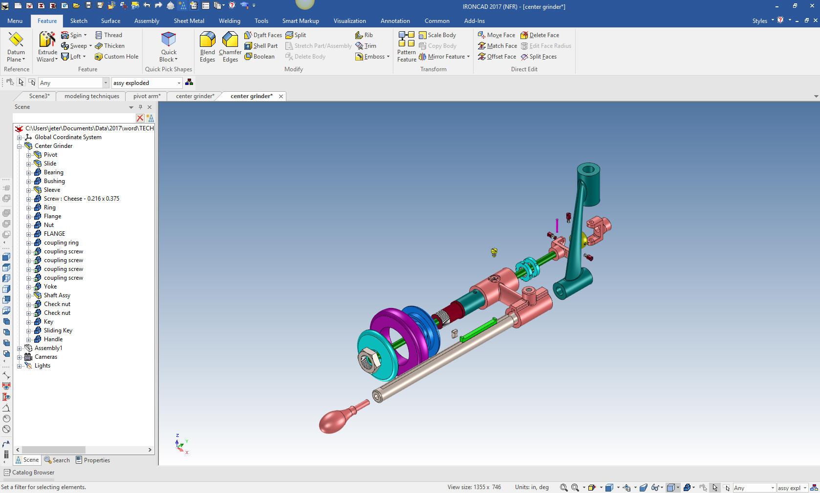
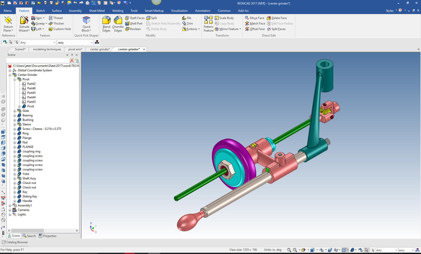
We have a couple more parts to add to our assembly. The true
single model environment is by far the most productive feature in 3D
CAD. Watch how easy it is to design parts in context or top down.
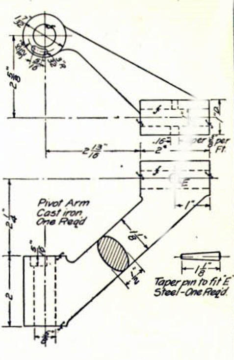
We are going to model the Pivot Arm. This piece needs to utilize
surfacing. IronCAD surfacing is not as robust as I wished it was. I
have been selling 3D CAD for 30 years and only about 10% of us use
it regularly. But once in awhile you need it. I struggled a bit with
IronCAD to create this part but I finally did it. It is funny, you
can spend two hours figuring it out and then it takes 5 minutes to
do it.
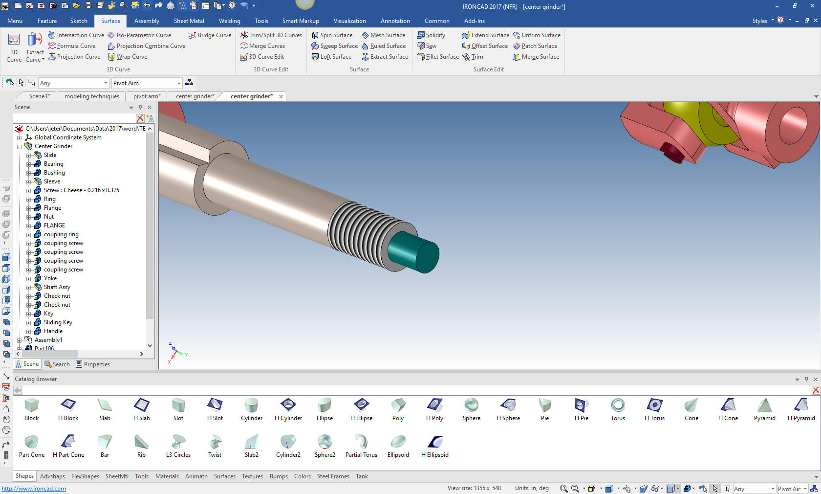
We create a new configuration called Pivot Arm.
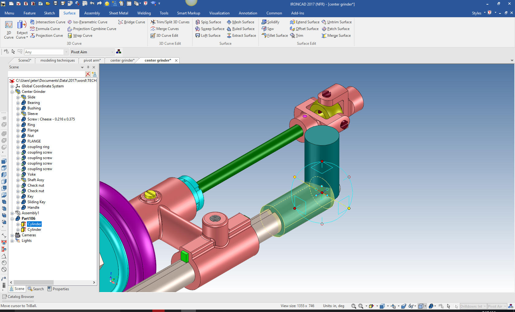
The first thing we do is drag and drop a cylinder with the right
mouse button. The allows us to create a new part. I have changed the
color to make it easier to follow.
We locate it by pulling the shape to the
mating face and sizing it.
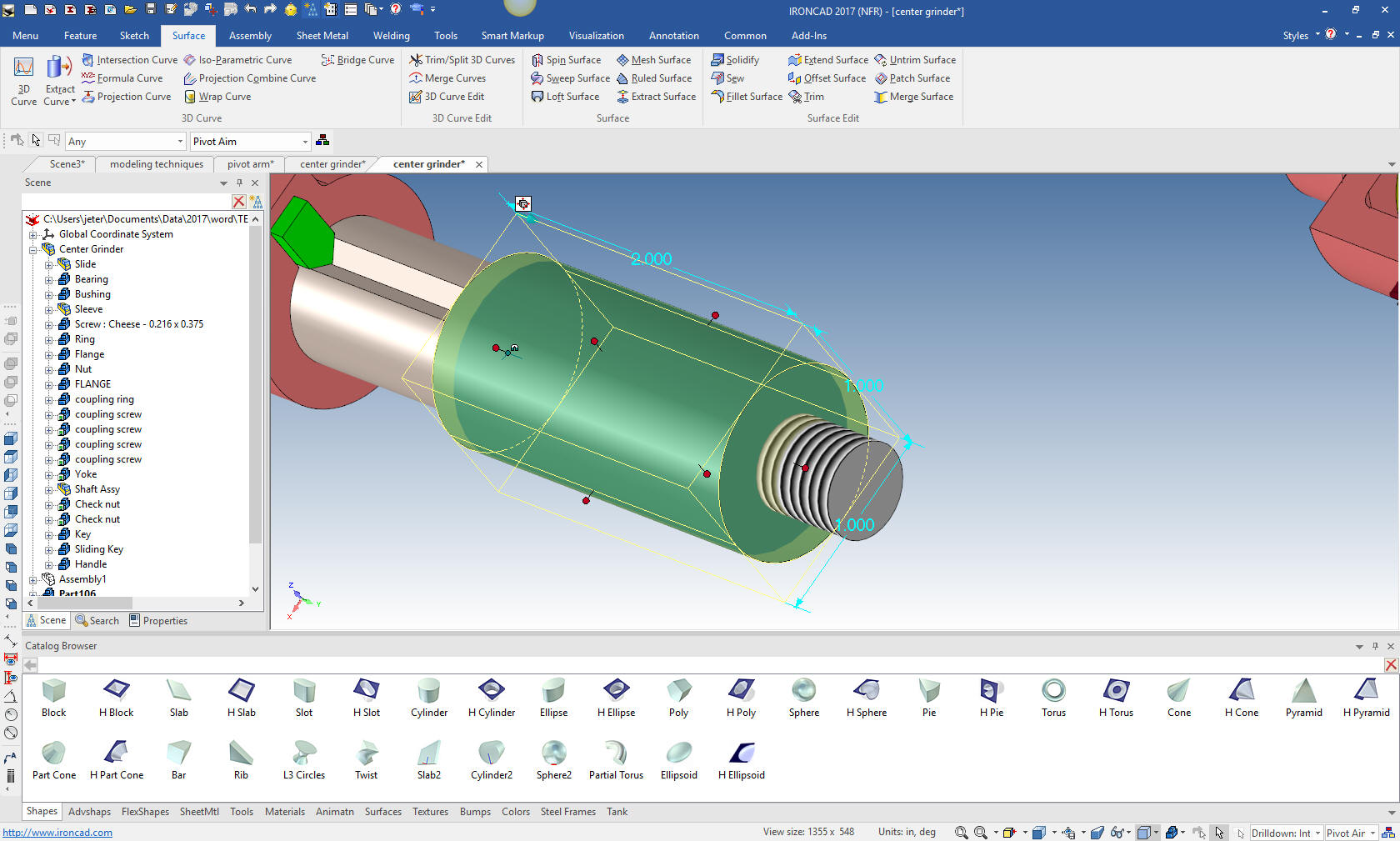
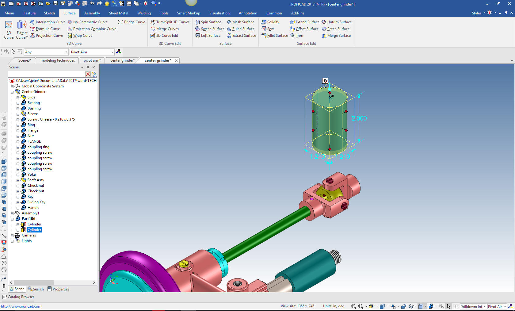
The
next cylinder is vertical. Nope, we don't have to drag and drop
another cylinder we just rotate the existing cylinder and copy it
with the triball. The cylinder still is a feature in the Pivot Arm
part.
Note: When working with catalog parts, you usually only
drag and drop one part. This is important when linking parts which
will be noted in the Parts List as duplicate parts.
Now we
move it into the correct location and size it.
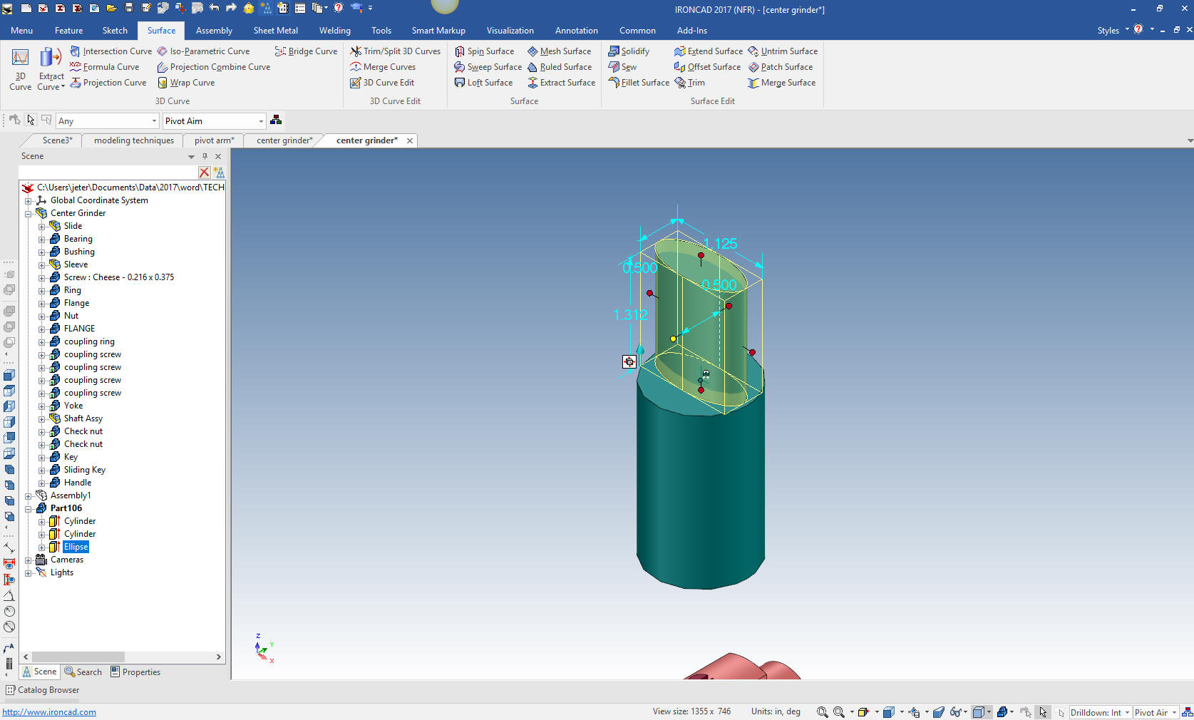
Then to the connecting ellipse. This a is
bit convoluted, the drawing is a bit obscure. I showed it to an old
pattern maker and he agreed on my interpretation. So we drop a
ellipse on the top of the cylinder and size it.
Note: We
design with shapes. Even if we have to sketch them and then locate
them it is a bit more simple operation.
I will now rotate with the tribal and move it to the center of
th cylinder and copy and locate the on the lower cylinder.
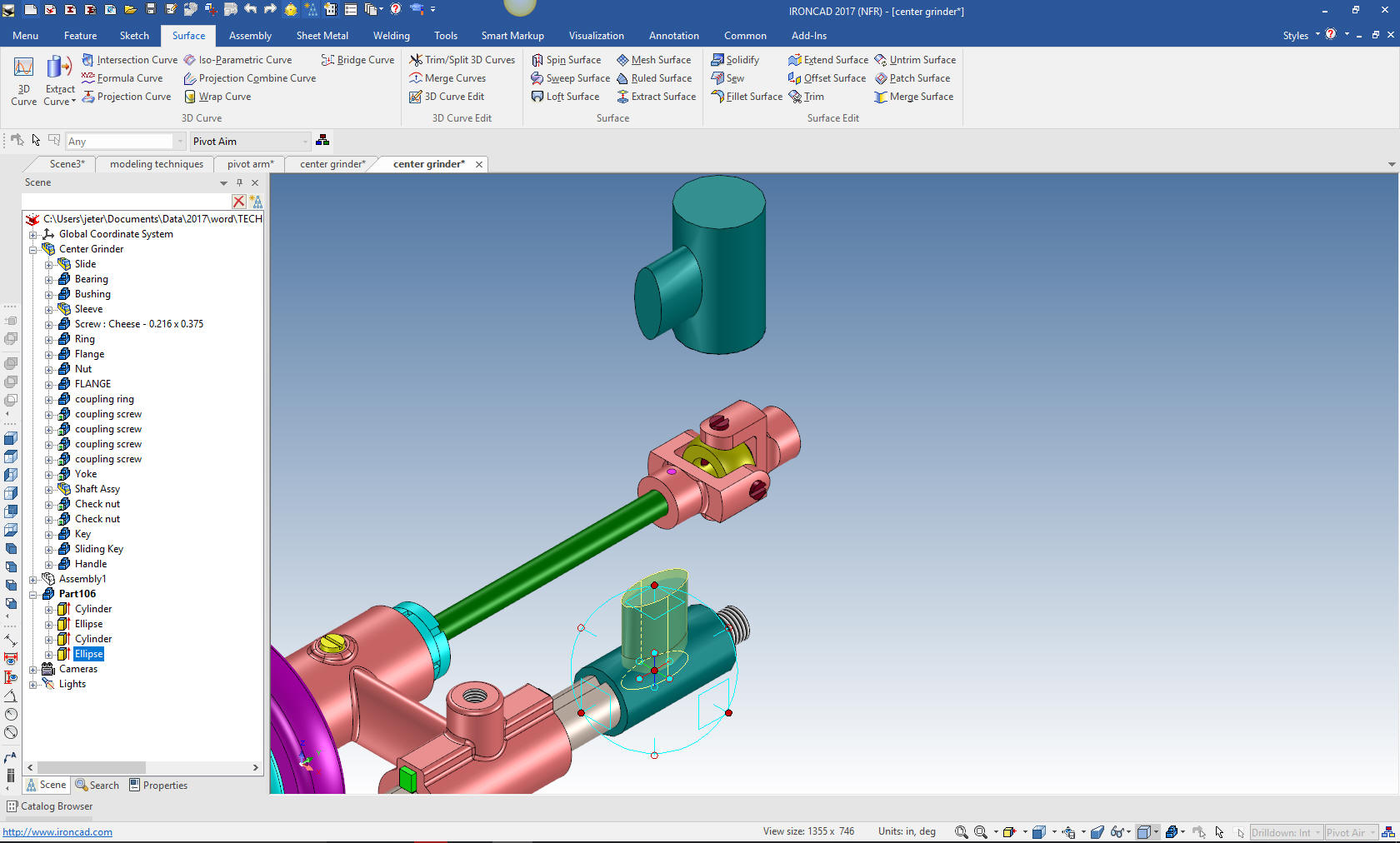
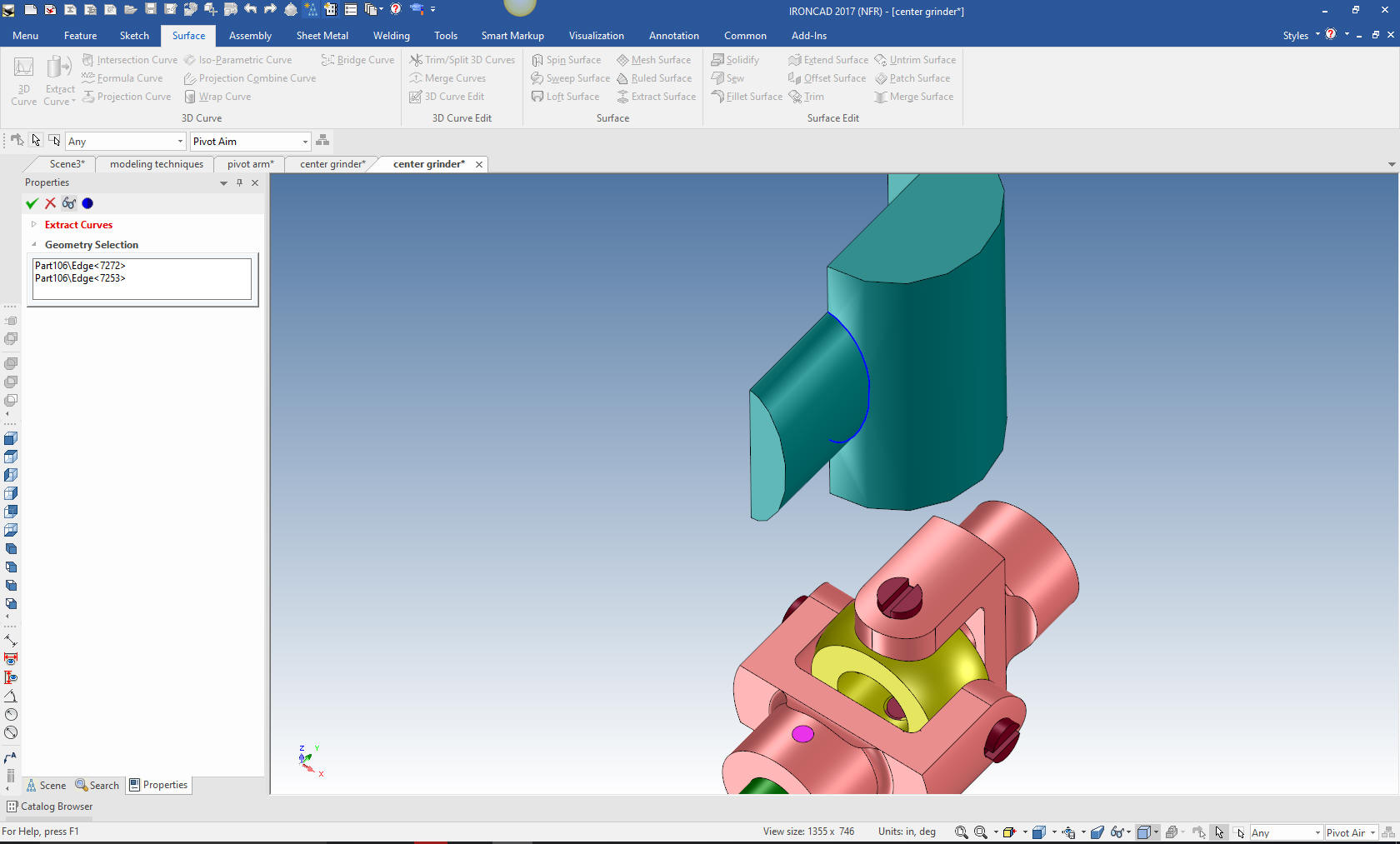
Now
this is where it gets a bit strange. I tried to create the
connecting bar surfaces with two full curves and it totally failed.
I was playing with it one day and found I could create the surfaces
if I split them. So I drop a hole block and center it and extract
the intersecting curve.
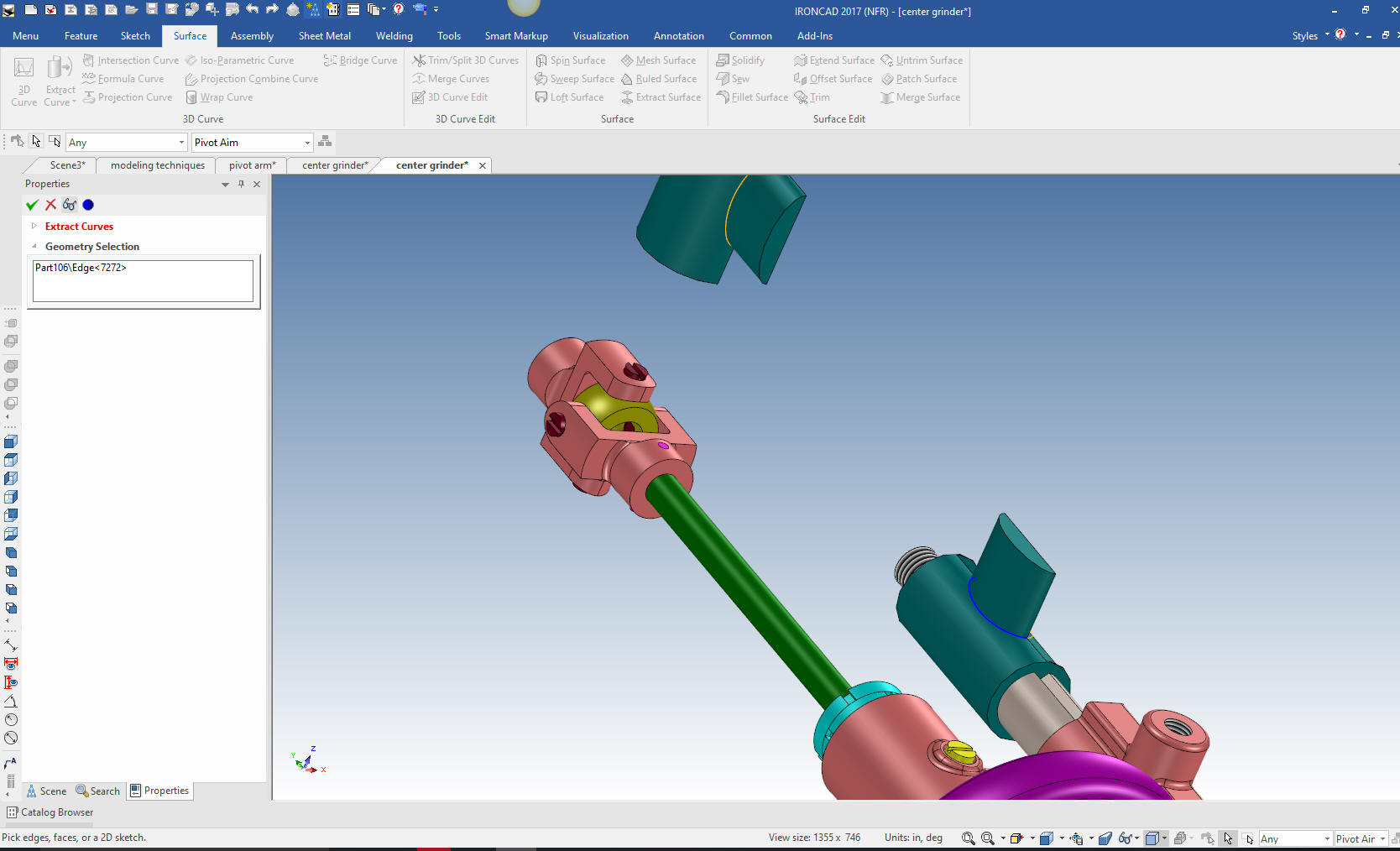
I
mirror the hole block on both ellipses and extract the curve on the
other side.
We
create two connecting lines and are ready to create our swept
surfaces.
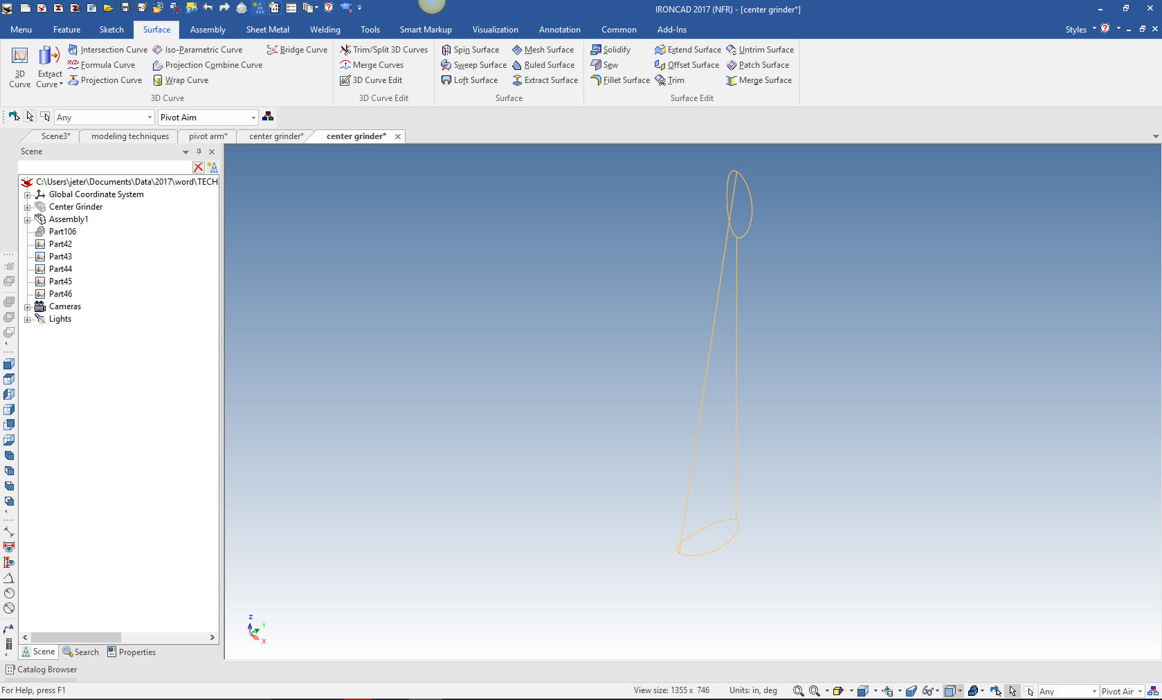
Now we create the swept surface with two sections and two
guides. We close off the ends with a patch surface and then solidify
them.
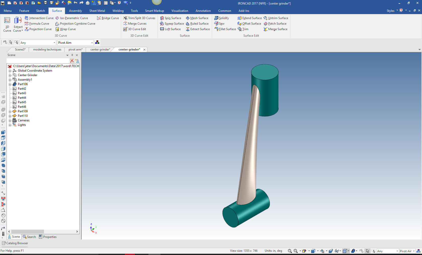
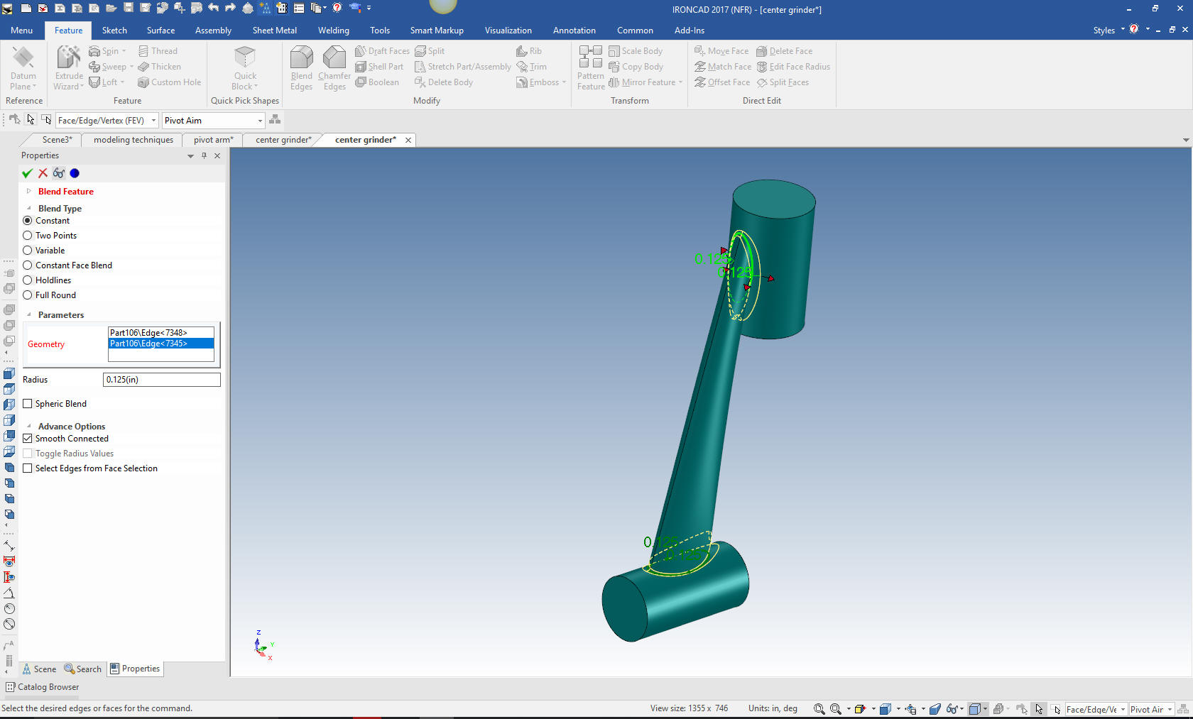
We now boolean union two pieces and put in the blends and we are
ready to complete the part.
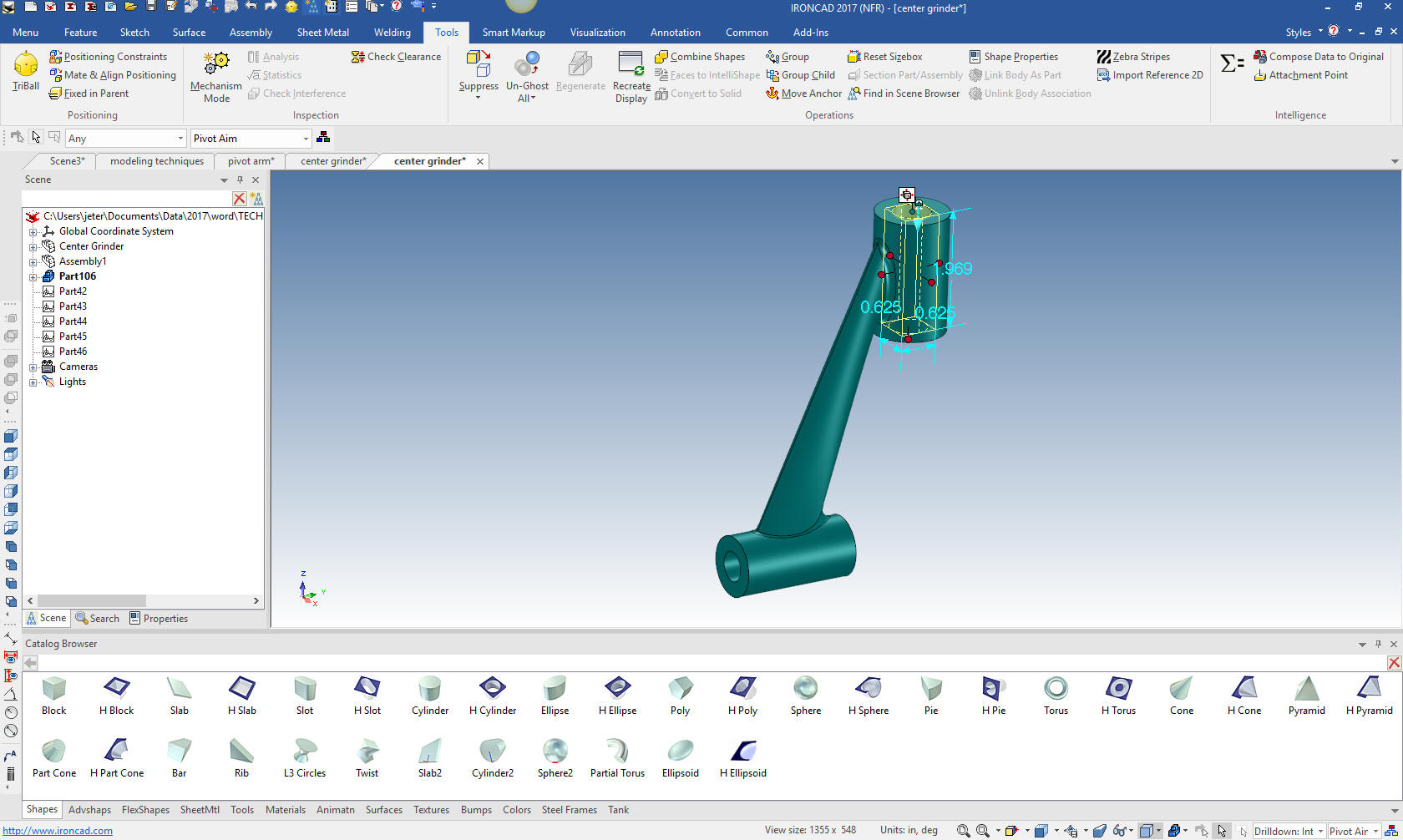
We
drag and drop the hole cylinders to the center of the two cylinders
and size them.
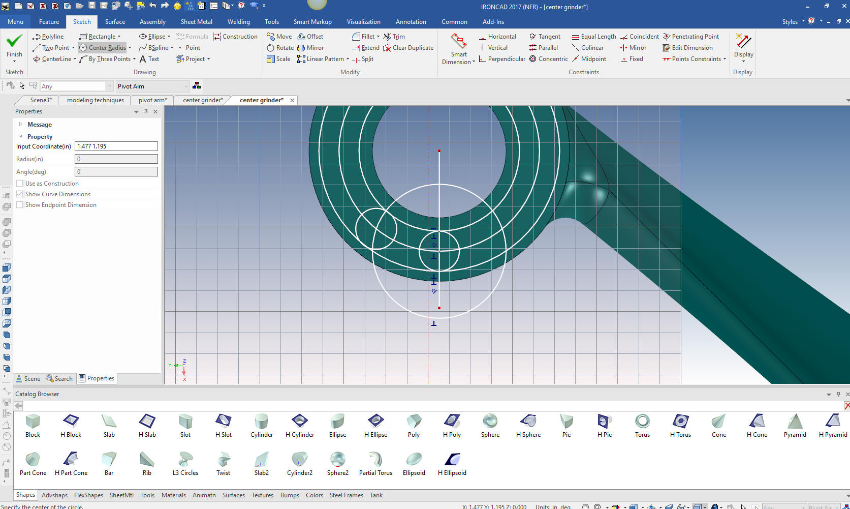
We
model the small slot in the bottom of one of the cylinders and we
are done with this part. We will do this using the extrude wizard. I
will show you my sketching technique. I projected the center circle
and edited the size to 15/32, then offset that line by 3/32 both
sides. I then created the circle to locate the center of the 3/32
radius then create the two 3/32 radii.
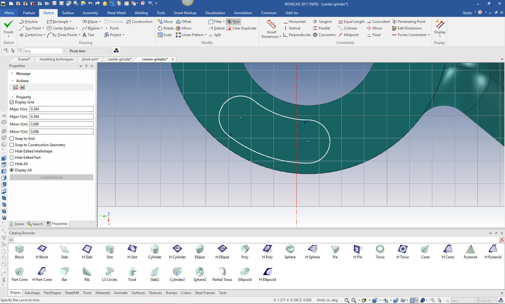
I will
just trim and delete the construction geometry. I know many of you
would probably do this much different.
We
exit the extrude wizard and pull the feature to the correct depth.
We are done with the Pivot Arm. I will stop here for today.
We
can use the existing exploded view to move the other parts into
place with the triball.
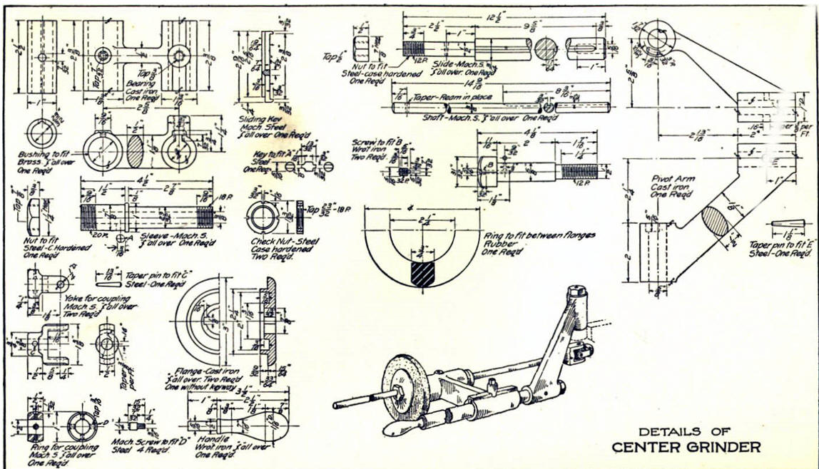
Here
is the original.
If you would like
to try IronCAD, please download for a 30 day evaluation.
For more information or to download IronCAD
Give me a call if you have any
questions. I can set up a skype or go to meeting to show this part
or answer any of your questions on the operation of IronCAD. It
truly is the very best conceptual 3D CAD system.
TECH-NET Engineering Services!
We sell and
support IronCAD and ZW3D Products and
provide engineering
services throughout the USA and Canada!
Why TECH-NET Sells IronCAD and ZW3D
If you are interested in adding professional
hybrid modeling capabilities or looking for a new solution to
increase your productivity, take some time to download a fully
functional 30 day evaluation and play with these packages. Feel free
to give me a call if you have any questions or would like an on-line
presentation.
|
| |
|