Corrupt 3D CAD Parts
| |
|
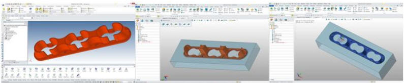
Most corrupt parts are due to poor or incorrect creation. The history only design systems can put you in a corner and demand some bizarre solutions that can corrupt the part. Direct edit does offer a bit more flexibility. While the part looks fine it may not export successfully. This is devastating when it needs to be correctly imported into another system for machining or it is a plastic part that needs to be used in a Cor/Cav split.
While we know that history and direct editing can
create corrupt parts the situation gets more complicated when we add
surfacing. When we use surfacing for design we lose all associativity. We
need to move to a hybrid modeler that can take the surfaces and heal
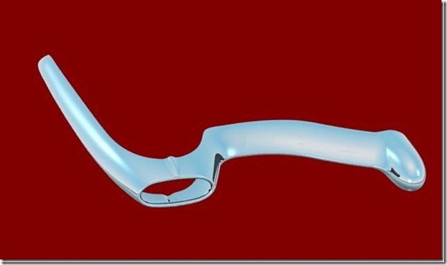
Most surface files can easily be transferred between CAD systems with surfacing functionality, using IGES. As you can see in the reverse engineered 1959 Corvette Bumper below was transferred to Alias from CADKEY. ZW3D has surfacing that can be used standalone. IronCAD has intermediate surfacing mostly to enhance the solid modeling. Solid model morphing is now becoming available. They have similar problems with complex surfaced hybrid parts. The move out of radii and straight curves puts us into a more complex level of design. When we use morphing and export the model it will take a robust hybrid modeler to do any modifications. The goal of most design is the manufacturing of the parts. We have to know how the part is going to be manufactured. Not only do we have to make sure the documentation is complete and correct but that the part can be used and is not corrupt. Any modification at manufacturing level to "fix" the model just opens the door to Murphy. Remember, 99% of the time the supplier will not be using the native 3D CAD system, so provide the due diligence to make sure the part is not corrupt. A quick check is to export and then import back into the system and take a look. We are now, with MBE (Model Based Enterprise), striving to use the model as the design authority. With this system, if the model is corrupt, there is no recourse to solve the problem short of having the part reworked by the original design group. The PMI (Product Manufacturing Information) offers no solutions to continue to solve the problem.
I was working with a CNC programmer on a Boeing Catia 5 part. He was trying to remove some holes in the process of his programming. He gave me a call and asked if I could help him. I brought in the part and there were these .010 edges all over the part. I could not understand how this part was released. You could see that the fellow just gave up trying to make the part correct and Boeing just let it go.
CADKEY or Catia? Boeing’s Billion-Dollar 3D CAD Mistake! I have tried to get CNC to fix my problem on the reverse engineering of a 1959 'Vette Bumper and they had choice words for me. I had to go to another program and CAD user to fix it.
Reverse
Engineering Success!
Here is the situation that sparked this article. I just sold an engineer ZW3D
Lite and a seat of KeyShot. He is an experienced NX user and found that ZW3D
Lite easily filled his new personal needs. As we were talking he asked if
ZW3D could do healing. It includes a robust healing process. He didn’t have
the time to learn and asked if I would look at the part. I have been in 3D CAD for over 35 years. I have used, sold, supported and trained a variety of 3D CAD products. My first systems were wireframe, then surfacing, then direct edit solids and finally history based design. I am very familiar with all of the design concepts.
Conceptual Design which 3D CAD Paradigm is Best? Feeling a bit comfortable I sent it off to my customer. He imported it into Creo, sent it off to NX then to Catia 5. By the time it got to Catia 5 the part came in as separate faces. This was unacceptable.
Being like a junk yard dog, I went back to do more review of the part and I found a few more
problems I could not fix. This part was poorly designed without any
consideration of the integrity of the part. I do not know what system in
which it was designed, not that that has anything to do with a poorly
designed part. It seemed like he/she was filling gaps with surfaces that
didn't create tangency with the adjacent edges. It was a poorly designed and
modeled part. There was virtually nothing I could do short of rebuilding the part. My customer was not
interested in making the part only using it as a purchased part in another
fabrication. So I did one more thing. Since it was going to end up in Catia
5 I decided to create a Catia 5 .CATPART with ZW3D Lite. It imported the Catia 5 part into IronCAD, CADKEY and
ZW3D, but failed in Onshape. So I was not sure how it would do being read by
Catia 5. Who knows. I sent it off to the customer. I will update
this article if he wants to follow through. But this made me realize that as designers we are responsible for creating parts that can be read without a problem by other systems, mostly manufacturing CAM software like Mastercam and ZW3D CNC. This part was so corrupted it could not even be use by the native systems manufacturing modules. It was unmanufacturable. I have experience with hybrid system that can take a
part down to wireframe and rebuild it with surfaces or use for re-creation
in solid modeling. I see that the current systems cannot solve these
problems. This fellow has Creo, NX and Catia 5 available and I had to use a
package that costs hundreds instead of tens of thousands of dollars to solve
the problem.
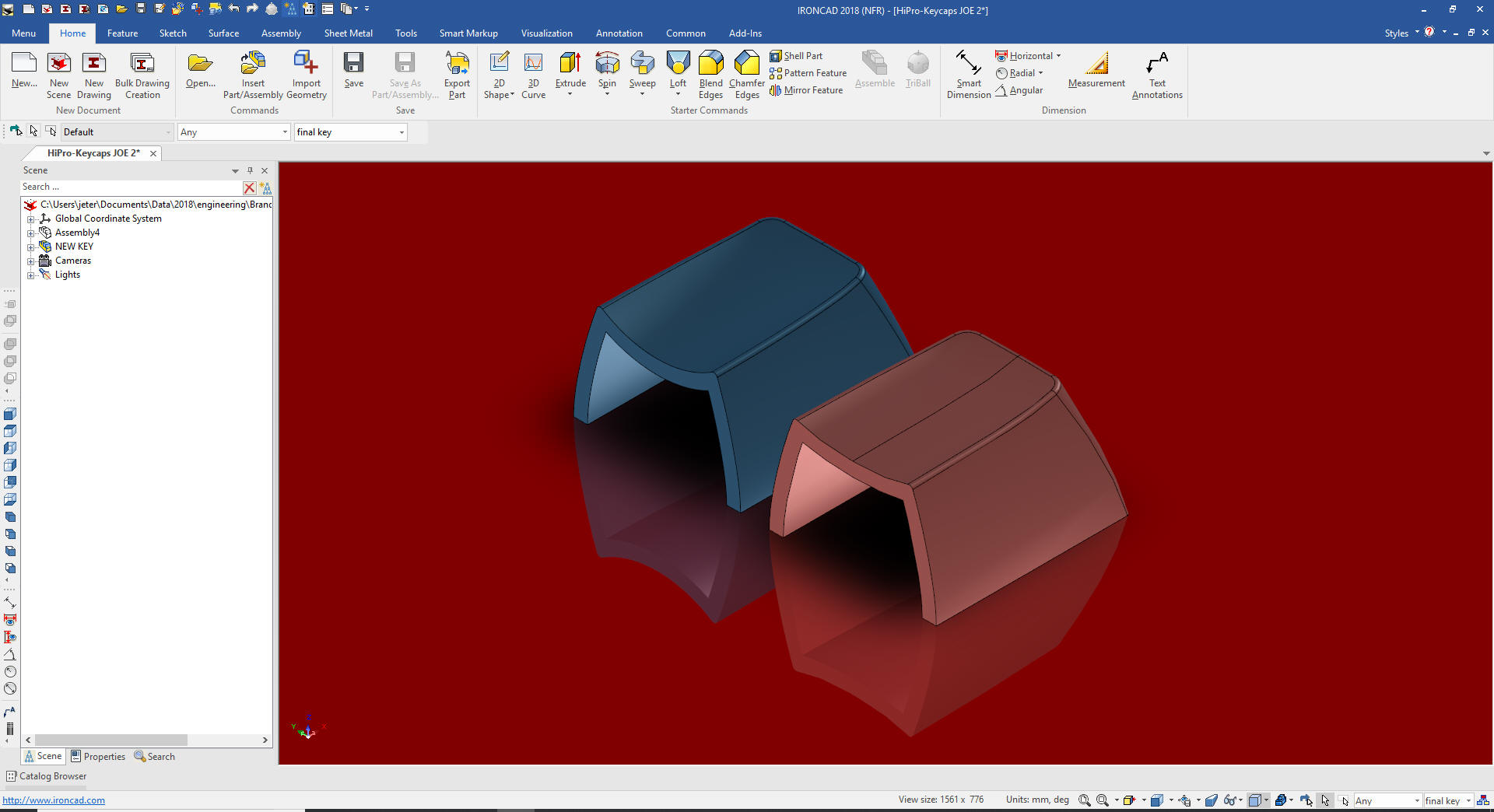
Solutions There are tests you can make to see if your part is
corrupt. Export it as a STEP or other neutral format and import it back into
your system. If it comes in as a brep (dumb part) and looks fine, then you
are probably okay. If you have a few problems, it maybe with some blends.
You can do a zebra strip analysis to see if there are some tangency problems
with the blends and correct. It is better to find it here. This part was
unusable and would be sent back to be redesigned and recreated. Today the trend is away from completely detailed drawings of the parts. In the beginning I would just send my plastic parts as a neutral file without any documentation. But when the parts were shot I would find small errors. None that would alter the use of the part, but mistakes anyway. Creating fully detailed drawings is like a second check on the design for errors or a better design. I will tell you if it is hard to detail it will just as hard to manufacture.
Here is a video that shows how easy it is to work with a corrupt part in
ZW3D. I have been healing parts from the very beginning since I was working
with CADKEY that was direct edit only. Boolean join could be a bit of a hit
and miss in those days. We had to augment our solid design with surfacing
and healing the model was part of the design process and still is in some
cases. This is one of the only videos showing the healing process. Most of
the cookie cutter design of the Pro/e clones rarely has many problems. Incompatiblity? This level of incompatibility
reminds me of the Catia 4 to Catia 5 fiasco. Dassault in its wisdom created
a completely new system and named it Catia 5. Many of us use Solidworks,
AutoCAD, Inventor, CADKEY, ZW3D, IronCAD and Solid Edge and all versions can read
earlier version (Yes, I know the lack of backward capability bugs us). So
when a company names the new program the same as the old you would think the
same thing. It was nothing of the sort. It was a completely new package and Catia 4 and Catia 5 could not read each other’s files. Dassault didn’t even provide a translator. Think of this. Boeing and Airbus have been using Catia
3 or 4 since 1985. So you have legacy data from 1985 to 2000 and beyond. No
one ever stops using the earlier system when you have 15 years of legacy
Catia 3 and 4 parts.
We supplied Boeing with a solution. We sold them
IronCAD that could import and export both Catia 4 and 5 part/assemblies. My
Boeing contact would take Catia 5 parts and convert them to Catia 4. It was
not a straight forward translation. Catia 4 could only import files max 34
meg files. So he would work in IronCAD and play with the assemblies and save
them in a manageable size. It took him less than an hour to create the
files. But not only could he convert Catia 5 files, he was also reading the
native files of Pro/e, UG, Solidworks and Inventor and converting them to
Catia 4 or for that matter Catia 5. Catia 4 could actually use the files. Sadly, Catia 5, being a poorly designed history based only system (still is) could not use the parts except to maybe to recreate the parts or use for tool design. I gave a presentation to the Boeing group that was
responsible for converting OEM parts from other systems to use in assemblies
though out the commercial division. They were taking two weeks to deliver
the parts/assemblies to the requesting groups. I am not sure what they were
using but it was time consuming and expensive. They just were not
interested. I suppose it was because we could supply each group with an
IronCAD modeling only package INOVATE ($1970.00 full retail) and do away
with the group all together. Ah, those politicians. Sadly, it even got worse at Boeing when they implemented the unworkable Dassault PLM (Product Lifecycle Management) and MBD (Model Based Definition). Dassault is responsible for keeping Boeing one of the most ignorant and isolated manufacturing companies. Their lack of interoperability is beyond belief. But that is another story. MBD truly requires a robust hybrid modeler to really be called MBD.
TECH-NET Engineering Services!
If you are interested in adding professional hybrid modeling capabilities or looking for a new solution to increase your productivity, take some time to download a fully functional 30 day evaluation and play with these packages. Feel free to give me a call if you have any questions or would like an on-line presentation. |

TECH-NET ASSOCIATES | RENDERING OF THE MONTH | CAD•CAM SERVICES
HARDWARE | TECH TIPS | EMPLOYMENT | CONTACT