|
A Short Primer and History of Dimensioning | ||
|
History usually starts for everyone when they are born. Most professions are the same way. So, we will start in 1965 when I entered the industry. No use going earlier, drafting and detailing were the same for decades may be even for centuries. Yes, I first walked into a Boeing drafting room in
1965 after a Boeing sponsored training course offered by the government My First 17 Years or "How did we do it without 3D CAD!" Drafting is the design and documentation of our parts
and assemblies. It consists of creating orthographically projected
views on a sheet of vellum, linen, mylar or any other translucent media so
prints could be made of it. The originals were stored in a vault in a large
company and fire proof cabinets in smaller companies. They were very
valuable. Detailing Detailing is what dimensioning is called in drafting. A print of a design layout created by a design draftsman or engineer would be given to the drafting group. The lead draftsman would assign it to a less experienced detail draftsman whose job would be to create a standard drawing of the part which included the layout of the view, adding the dimensions, tolerances and notes in standard format send it to a checker who would mark every input on the drawing highlight red for incorrect and yellow for correct. This could be questionable by the originating draftsman and there would ensue an argument. It was an exercise in futility! The checker always won.
So, what we are going to learn is the basics of
detailing. Why do we detail. This seems obvious. If you don’t the person making
the part would have to measure the drawing which would not be exact.
Dimensions are rarely measured they are drawn to locations that may be
developed by using trigonometry. We have to know exactly where each
location is. Trig was the draftsman’s tool. I remember being introduced to
3D CAD. I would check the locations 3 times and the CAD system would do it
once. I did this for 3 weeks before I trusted the CAD system. Much of the design was done by the draftsman. He/she
would then create the drawing from their layout. Similar how it is done in
3D CAD today. But we will get into that later. So, let’s get started.
We are only going to put dimensions and annotation on existing graphics.
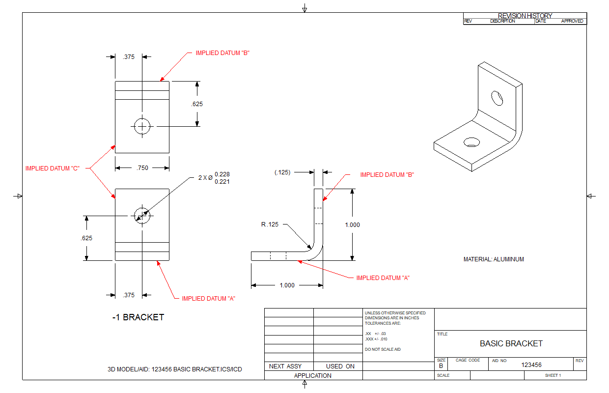
Here is an angle bracket.
This is great inf
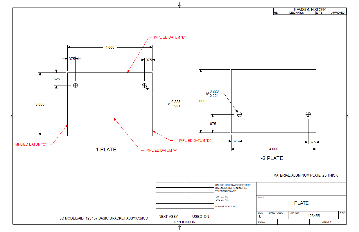
Now let's look at the plates. We create both plates on the same AID by defining them with dash numbers.
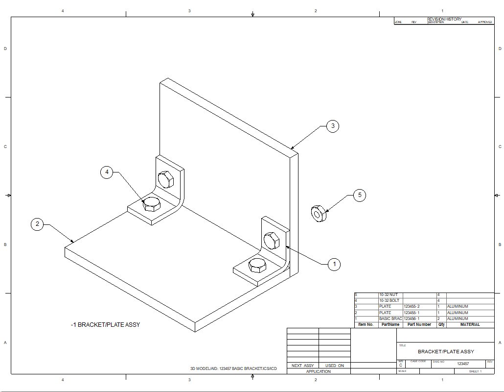
This assembly requires little concern on tolerancing since everything floats easily within the tolerances used. Now let's change the angle to a single part. We know the two holes are now going to match another part and now have to be related to each other to not allow an accumulation of tolerances.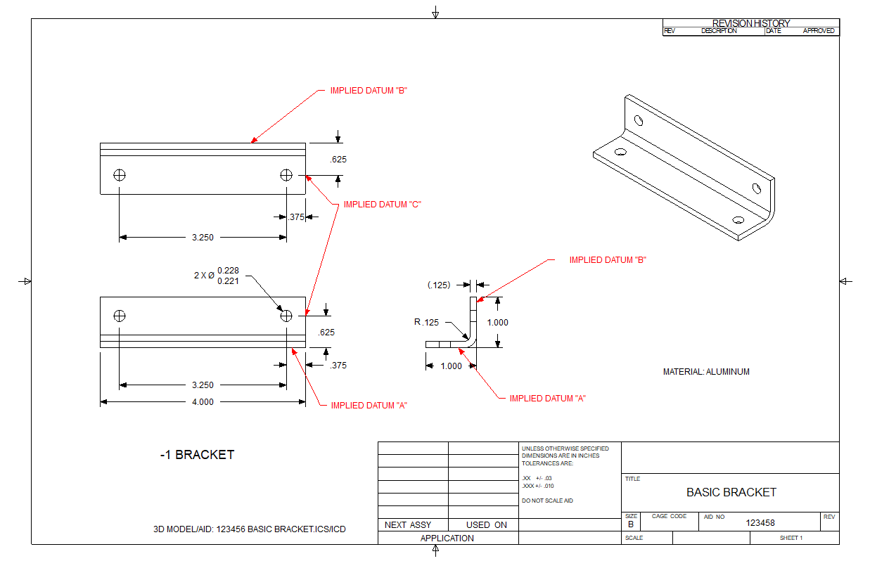 Here is the assembly. 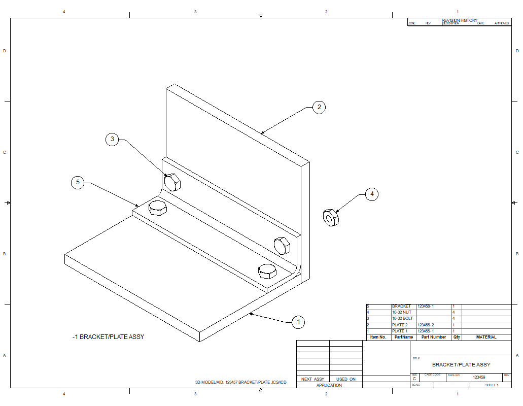 Now the plates. This is a copy of the original plate drawing. Only the way it is dimensioned is different. We now have to tie the two holes together to match the angle. We do this to eliminate an accumulation of tolerances. If we kept it the same as the prior plates there would be +/- .010 for the .375 on both sides creating a +/- .020 situation. The AID (drawing) and model serve two purposes: Definition of the part and for the inspection of the part. 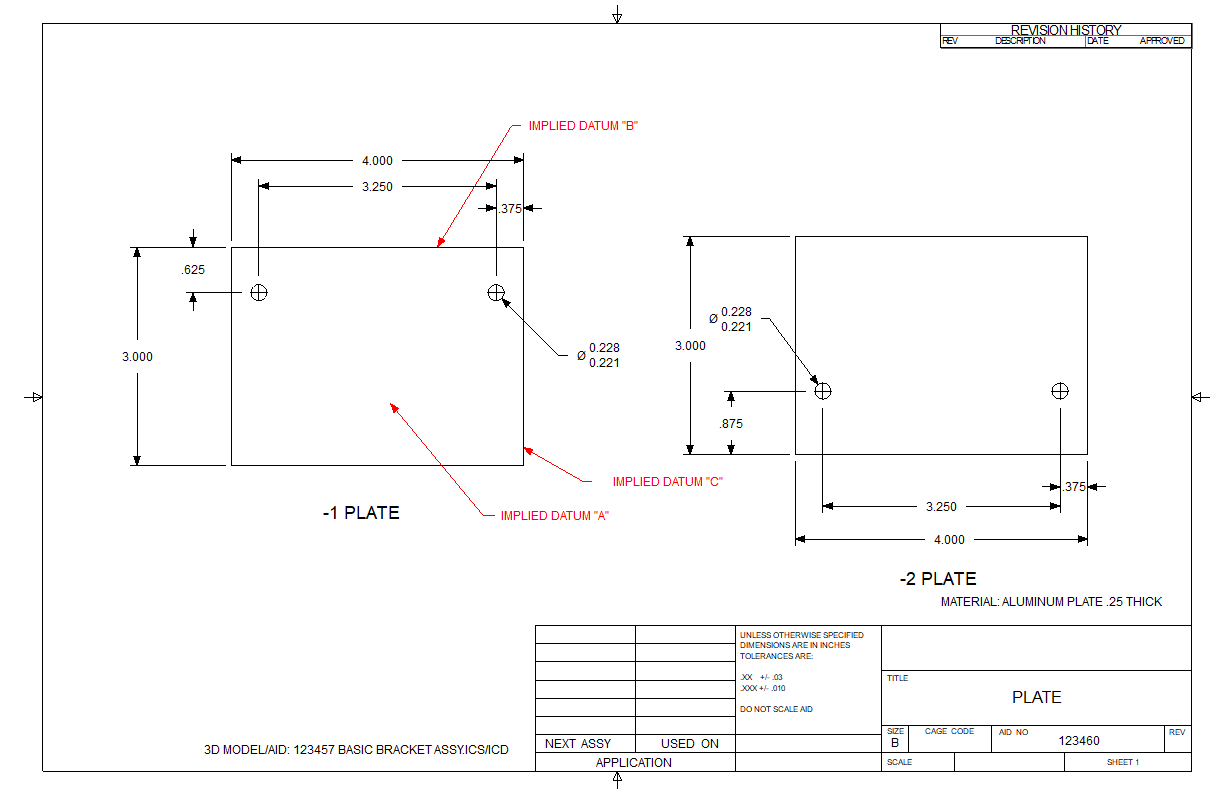 Enter GD&T (Geometric Dimensioning and Tolerancing.
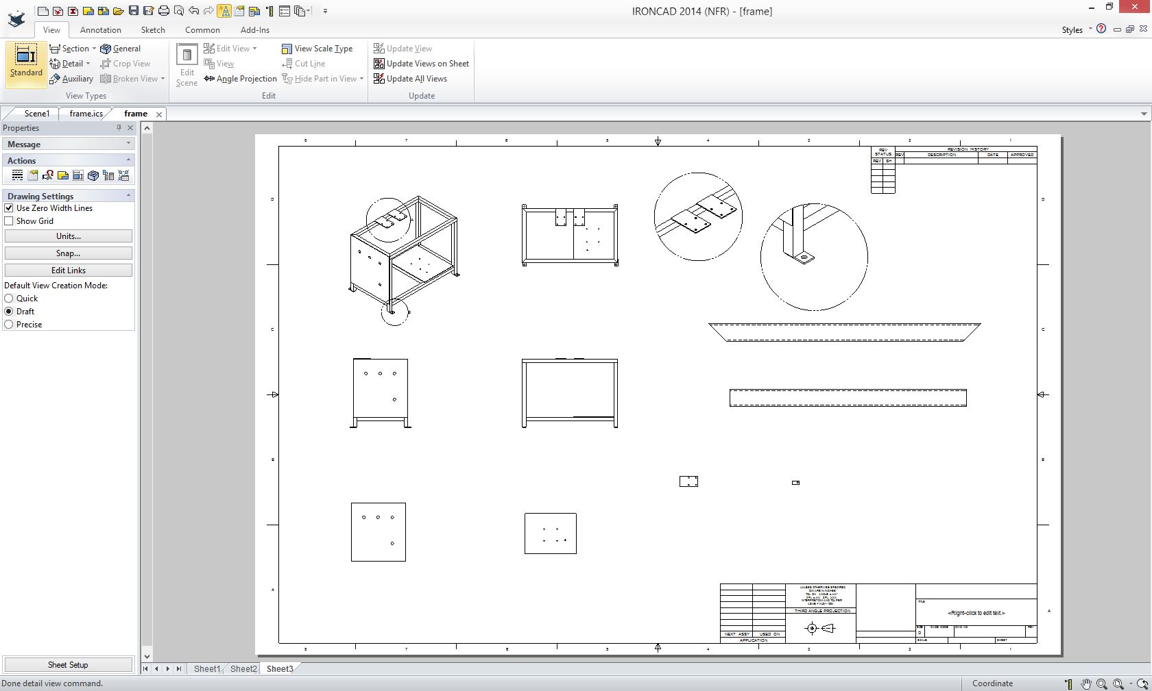
I do not want to get into the minutia of GD&T, just how it is applied in these few cases. It was used sparingly in this application. Let's take a look at the bracket with GD&T.  Now the plates 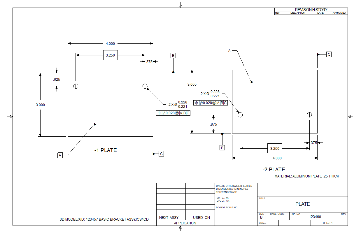 As you can see we are getting the same results as the conventional dimension with a bit of bonus tolerance with the true position. You can see the .028 diametrical tolerance zone as compare to the +/- .010 or .020 total square tolerance zone. But when you show the actual tolerance outer feature if is very little benefit. The center has to fall into these two zones. The blue circles are the max material at the four corners just to give you an idea. The yellow circle is a location on the diameter. Remember this is all only for inspection. 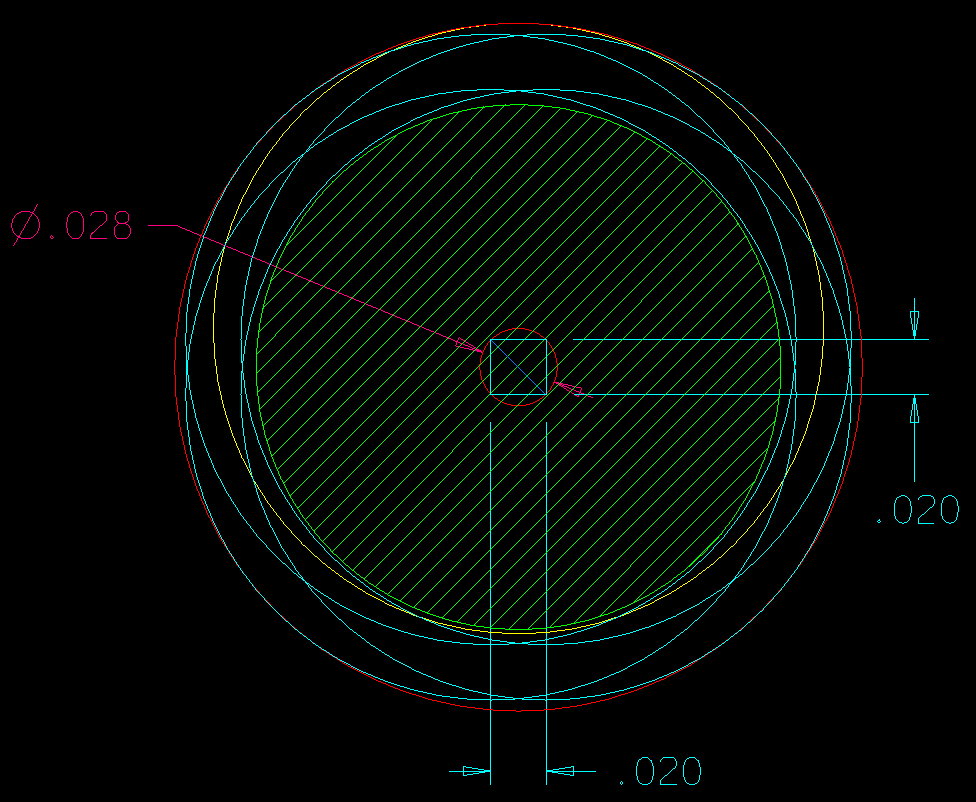 Before we move on I would like to show you what tooling did with our drawings. Engineering was not the only group creating drawings. Tooling had their own process. Tool design would create tooling drawings to make the part easier to manufacture. Here is a conventional drawing. Can you define the implied datum? Drawings served two purposes: Part Definition Part Inspection 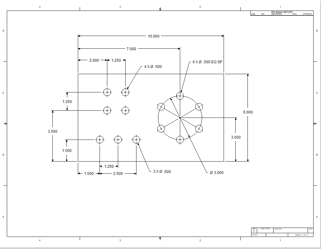 Here is the tooling drawing. Ordinate dimensions? I remember seeing this for the first time, "how can they inspect it", it violate all dimensioning rules. That was when I realized the original drawing was more of a inspection tool for them. Remember there was no copy and paste. The tool designer had to trig the X and Y locations. Now why would they do it this way? Go ahead guess! In those days they would turn knobs to correctly position the drill. They could only work in X and Y coordinates. So the tooling group would put the information into an format they could use. Today it is all driven by CNC. That leads to an interesting question. The machines today can easily hit .005. If you design to +/- .005 why are we doing all of this tolerancing? Couldn't much of it be covered by a UOS (Unless Otherwise Specified) note? Much of engineering is a hangover from the past and sadly some of it is reinventing the wheel, it takes a certain amount of knowledge to know the difference. 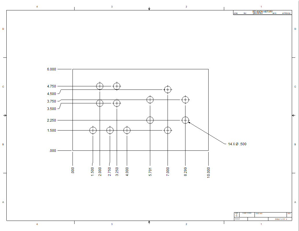 PMI - Dimensioning Today! Warning: Before even thinking about attempting PMI, you should have a good working knowledge of the above dimensioning processes! Now we will show you the bastardization of GD&T with the PMI (Product Manufacturing Information) which is the ugly step child of MBE (Model Based Enterprise and MBD (Model Based Design). This title was not assigned by engineers or draftsman it was the IntoTechs. It should be "Part" Manufacturing Information, since I have never seen it relate to an assembly PMI. But then these are parts that are going to be machined from the 3D model. Not all parts need to have the 3D model, like fabrication. Tubes, plates and other parts are not cut by CNC machines, but maybe by manual band saws. Why such a minimization of GD&T? I worked with PC based CADKEY in 1987. They soon developed working with planes. We could do 3D dimensioning, what is now called PMI. We soon found out it was not viable except for a bit of illustration. Why? the dimensions were just too cluttered. Well the MBE folks also found this to be true with PMI. It was even too cluttered with the basic dimensions, so they reduced it too the ridiculous level of minimization today. Sadly, this decision was not made by the draftsman of the day but those with a vested interest to implement PMI. Hmm, they soon eliminated draftsmen from the engineering world and told the design CAD engineers with virtually no experience it was now their job. They and engineering management did not have the experience to understand the limitations and destructive nature of this process. This basically eliminated checking as a step in the engineering release process. The importance of checking has all but disappeared from the complete engineering process. Could this mindset be the reason for the oversights that caused the crash of the 737 MAX? If you are a CAD design engineer, please, see if you can get this step back in the engineering process, our customers deserve to expect a well thought through and reviewed design instead of a costly short cut. It is your integrity and reputation on the line! The PMI is a virtually an uncheckable engineering document! The Ten Eyes that ‘See the Part’ Before It Comes off the Bench/Lathe/CNC Machine The PMI can only be called a 3D drawing. It was developed to have one file like the drawing. But the problem was that the popular CAD systems of today have a model, assembly and an AID. The AID had to be synched to the model. This was raising havoc in the data management. They could have just printed the AID as a PDF and had it stored along with the model outside the CAD system to solve the problem. But we will not get into that here. Let's create a PMI of these very simple parts. As I was creating the PMI I thought how to relate the holes. I know they don't use basic dimensions so I asked my crack PMI expert. It appears that basic dimensions are implied. So you have to sort of guess what holes are related. I seems like a bit of a problem if you have many hole patterns. 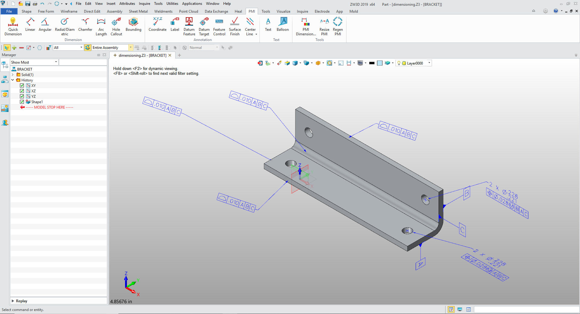 Now with convention and convention GD&T we can have one document with two parts we defined with different dash numbers. I don't know how they handle similar parts in PMI. You can see this is an incredibly silly engineering document. How long or wide is the part. Do we define the thickness with a note? Lots of ambiguous question since there really is no standard. They even have special software to create quotes from these idiotic PMIs. Quoting Tools: CAD Dimensioning Another Band-Aid for MBE! We will just do one of the plates. 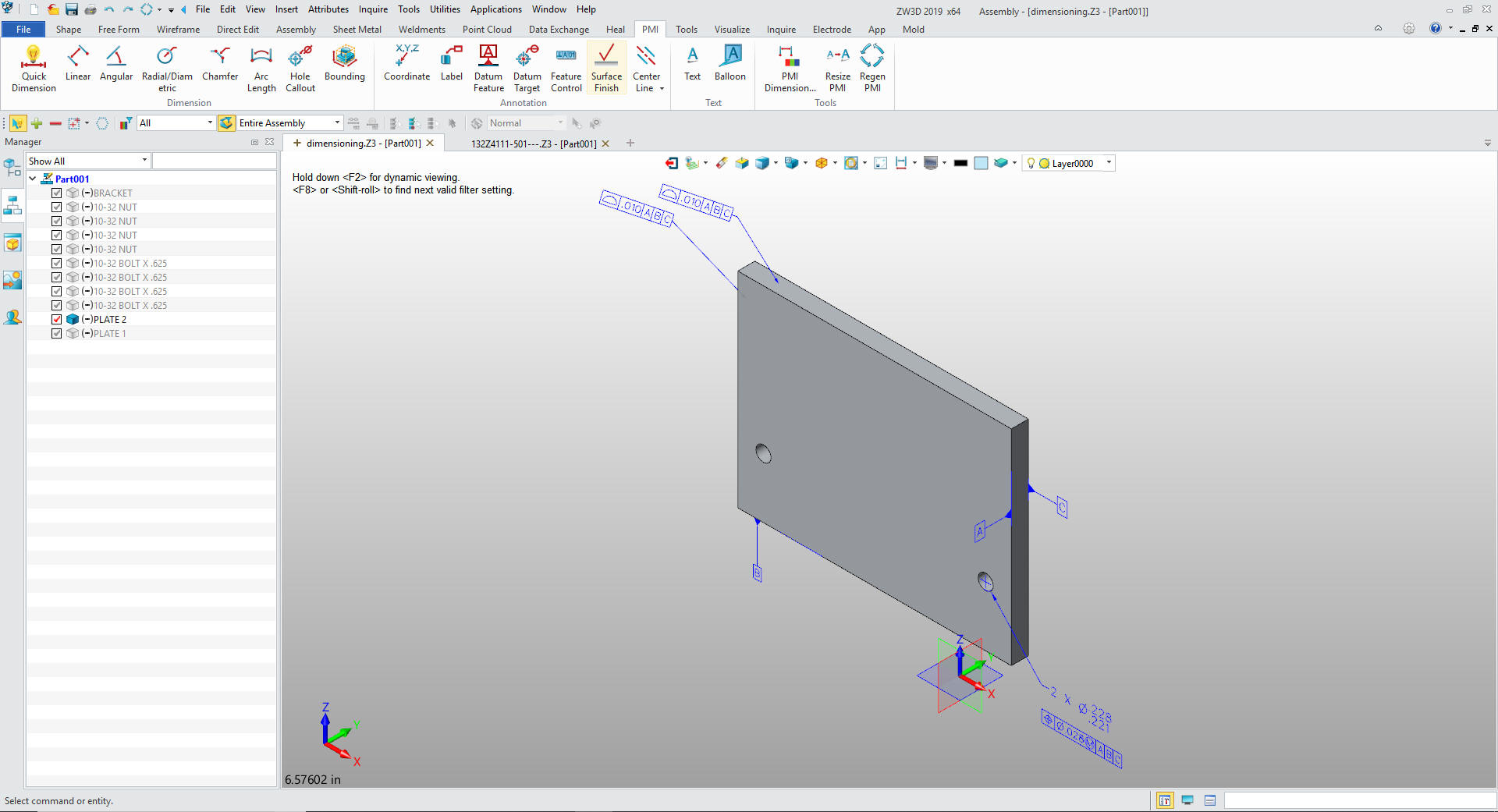 Then I started thinking (Something that the MBE/MBD/PMI people failed to do) the Model is "dead nuts" why are we going to datum in this case of true position. Since they have to use the model for inspection why not just inspect to the hole since it is located. It seems that all the features could be datums? Here is a Boeing manufacturing PMI. I have the ability to read PMI from Catia, NX, Solidworks and Creo with ZW3D. The GD&T is different in each CAD system since there is no standard. Notice the flag note on all of the feature control frames. Nope not referenced in the PMI. Don't believe me check this out. MBE PMI Validation and Conformance Testing Project 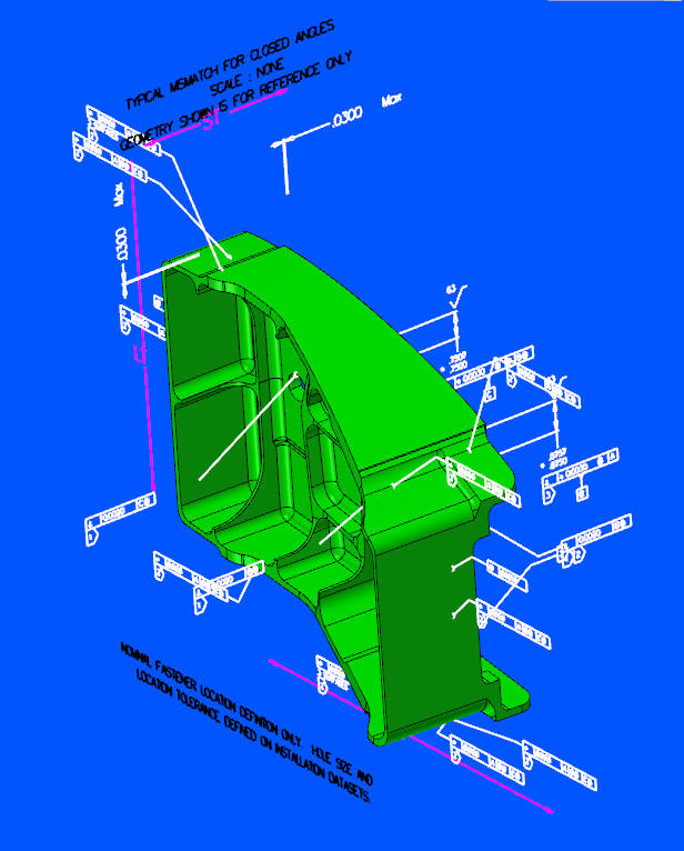 The purpose of a PMI was to have one document. Here is a note on the Boeing PMI. This indicates there may be multiple files. Even though this has this message this was used as a pattern for the CNC with the consultant.  Here is the other note. Fasteners? This is the only reference to Fasteners.  What is missing? All of the graphics that are delivered to manufacturing. Is this information pertinent? You can see even Boeing has not thought this though. I have said many times, that it is impossible to use a native CAD files as the released engineering documentation. 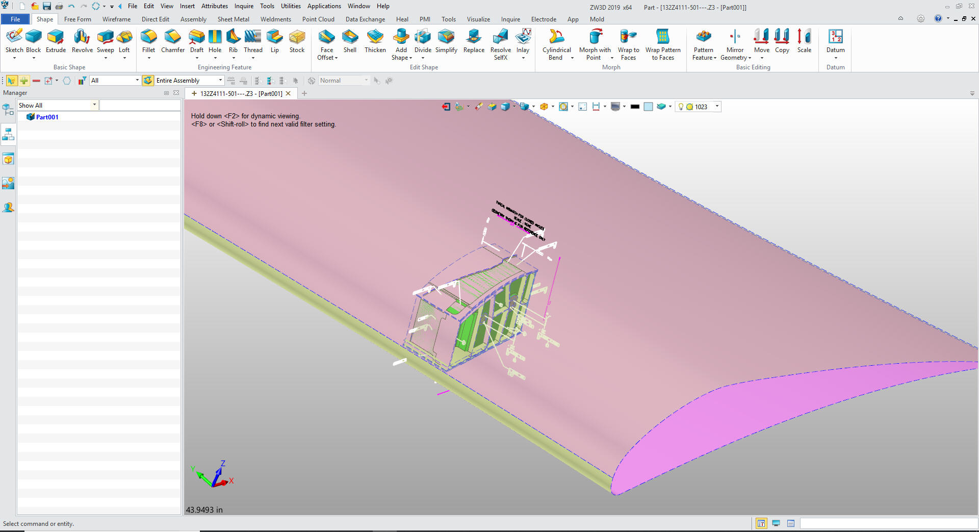 Now for a Bombardier production PMI. This is by far one of the worst engineering documents that I have ever seen. You can read more about it here PMI vs AID I will just show a few highlights. Here is the basic model for the manufacture. 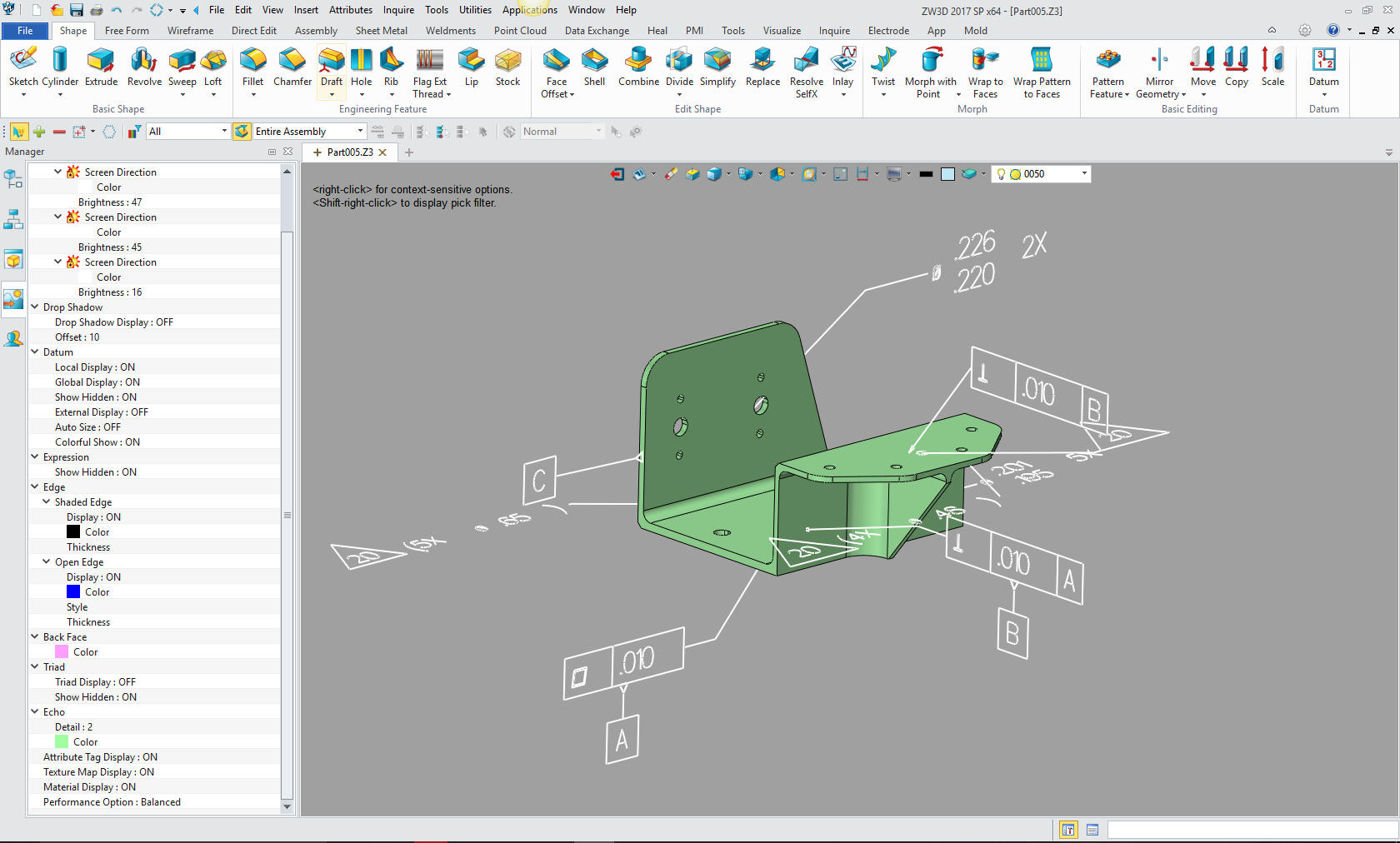 Here is all of the graphics included in the file 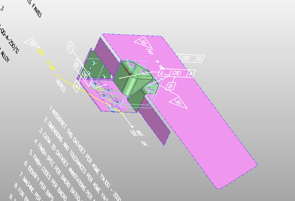 Now how do they tolerance the location for the holes? In the notes? You must be kidding me? 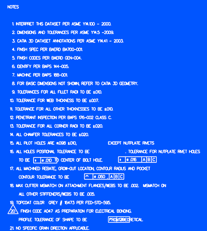 Here is more. I have to admit is looks like Bombardier (no identifier) is sticking to the one document idea. Can you imagine Boeings document control with just two files that relate to the same part. Nightmare. You can see that Bombardier is mixing the Conventional AID standards with the PMI. It doesn't look like specifics just throwing it all against the wall. 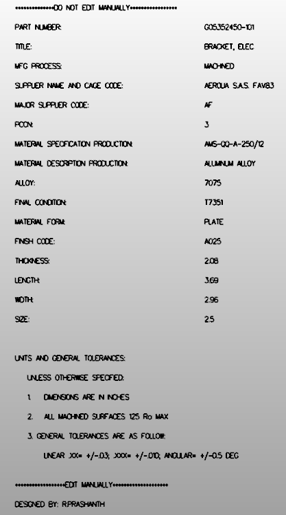 Here a conventional AID of the above part that gets delivered with the 3D model. Once a procedure is in place the supplier always knows there is an AID. The 3D model is always referenced on the AID. What do you think? What do you need to view a Catia PMI, the native software, the optional native viewer Enovia or a 3rd party viewer in this case ZW3D which is also a robust CAD system. What do you need to use and view a 3D model and AID as a PDF. A 3D CAD system and an Adobe Reader! 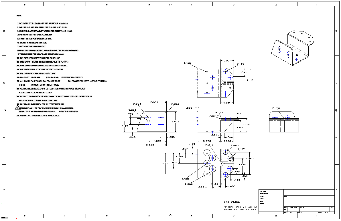 PMI violates so many conventional drafting standards it is amazing. Now I have to admit that PMI will deliver the necessary information to manufacture and inspection, yes, a bit obscurely. But as what cost, to checking and assuring the design is correct? The reason for a completely detailed AID is for the designer to provide a detailed check for errors and maybe a more optimal design. And also provides an easily viewable format for checking and review with common easy access. The effectiveness of this process cannot be denied? Just implementing this function would save millions, if not Billions in waste and slipped schedules.. You now have enough knowledge to protest the PMI process. It limits the design process and the results of that process is your engineering reputation. Here is a comment from a BSME PE using PMI and MBE. "The big problem is, any failure will be blamed on the responsible engineers and not an unworkable system. MBE is already being backstopped by drawings in many organizations that are forced to use MBE, but the drawings are frequently not in the release control process because they are not the "primary" data driving fabrication. A fine mess.." We can only hope the MBE and PM will have its run and will be eliminated when engineering is back in charge of engineering.Why MBE/MBD/PMI Will FAIL Why MBE/MBD/PMI Will FAIL Part II Here are a few more drawing configurations you may bump into. Inseparable Assembly Part of detailing is the type of AID you are going to create. This is an assembly, in this case, a sheet metal part with cinch nuts and studs. You can see that the sheet metal part is -2 and the assembly is -1. 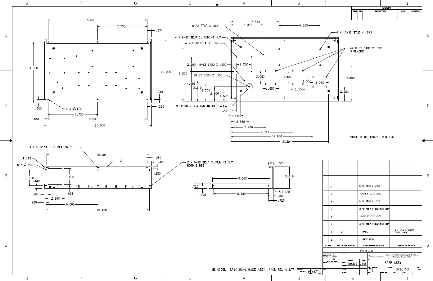 Inseparable Detailed Assembly The is an inspirable assembly with all of the parts detailed in the same AID. This is actually an AutoCAD drawing of a weldment. 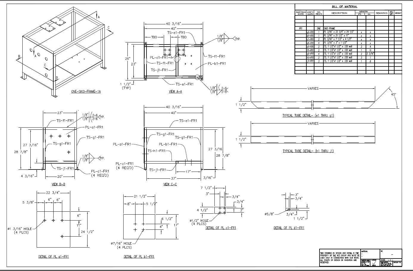 Here is the 3D assembly I did in IronCAD. IronCAD has a single model environment so I did all the parts in one file. I had the .dwg file available, but didn't use it since it was made up of simple tubes and plates. 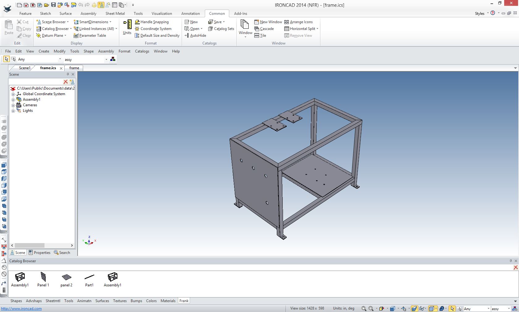 Here is the AID sans dimensions and parts list created in minutes. You can imaging how long the ISO view took in the original AutoCAD drawing.
This is an ancient Detailed Assembly. As you can see there is no tolerances. More than likely the parts were probably made in house with an understanding of how the parts would fit.  Here is the AID in ZW3D. 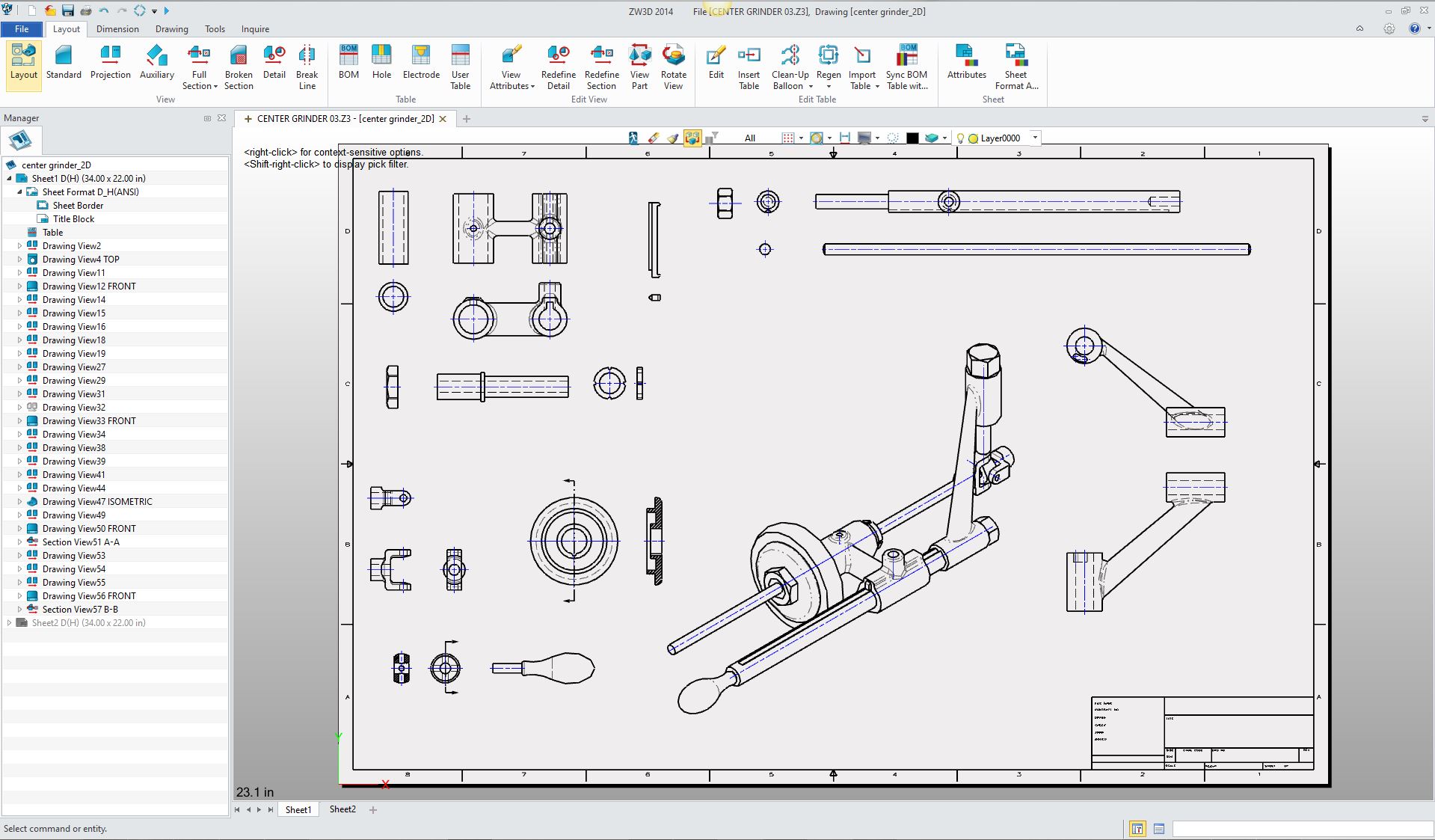 Here is the above assembly done in IronCAD and ZW3D in a single file. I have documented the process of creating this assembly and AIDs in this article. Effective 3D CAD Modeling Techniques 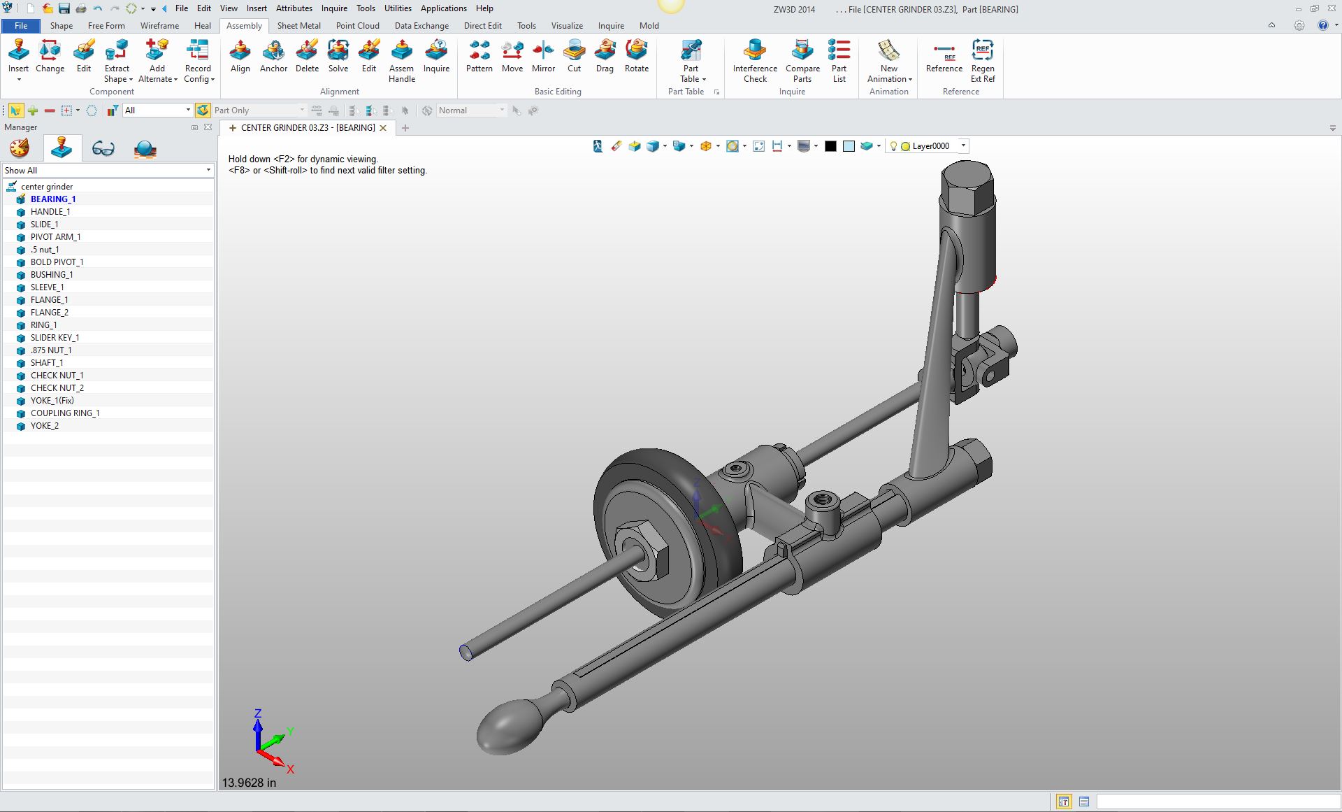 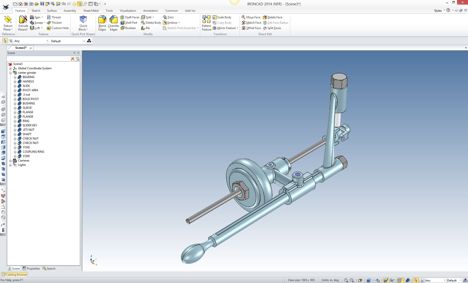 We have not gone into part numbers and parts list here. But here are a couple of articles that cover them. The Secret of Part Numbers Parts List or BOM? I want to tell you about two additional configurations. -1 shown and -2 opp This is two parts defined on the same AID. There will be two models referenced by this AID, but only model tied to it. So there will be two models that travel with the AID. -2 the same as -1 except as shown. I actually show both of these configurations in one drawing. This was the original part with thru holes. 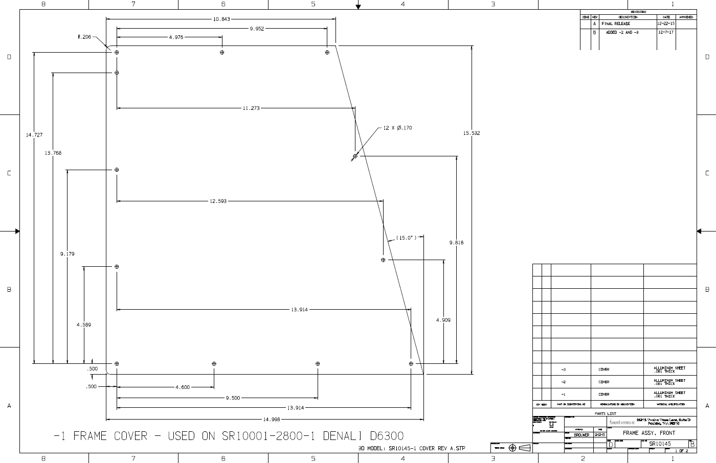 This is a new sheet with the new parts -2 and -3 with the added countersunk holes that makes the parts unique. You can see we now have two models referenced for the two unique parts. 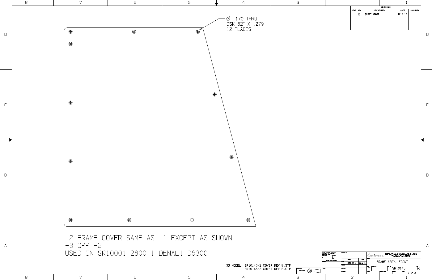 Many common parts can be defined in an AID under the same document number differentiated by dash numbers. This can give manufacturing the option of just editing a tool path or process and also eliminates the need for new document numbers to be maintained. Revisions Yes, even engineers make mistakes. Revisions can get a bit tricky. If they are small they are easily described in the revision block and server for a history of the model and document. You can make revision by not changing the dash number if the parts are completely interchangeable. You can even make a reference that the part has been completely revised. If you create a new unique part, you have to add a dash number. You can see in the above AID that we added a sheet under revision B. The ADCN (Advanced Drawing Change Notice) vs MBE This takes us to document control. I have a great cloud based document control system. We need to create the released documentation outside the CAD system, this would eliminate any dependence on a CAD system. It would be what you can only call a document bucket that can contain the complete definition of the part and and supporting documentation. It would be maintained not by engineering but a document control group. It would be accessible by any browser. If we could get engineering out from under the thumb of the powerful CAD vendors the cost of engineering and manufacturing would drop drastically. But sadly, the FOX (major CAD vendors) are in charge of the hen house and are dedicated to make sure their customers are completely dependent upon them. The Embedded Title Block! A PLM Solution! Standard Cloud Based Engineering Document Control Now I do not provide a part/assembly document control process inside the CAD system. I am sure if that could also be easily maintained by the document control group, providing easy access to the archived original files. Why did I write this article? Today the draftsmen are gone and all of drafting's responsibility has dropped on the shoulders of the design CAD engineer. Why reference CAD here? That is the only engineering design tool we now use! Take a look at what industry now expects of their design engineers. Engineering Yesterday & Today Engineer's Job Description The Search for the Purple Squirrel Take a look at this article. It describes the state of engineering documentation today. Engineers obviously need to be trained in some sort of standard documentation. There is no way around this, the design engineer has to do the documentation! Engineering Documentation Today! This was as a study on the failure of how engineers are now creating the documentation. Is it the engineers fault, hardly, the schools are not preparing them for the skills that are now required. Engineering management seems to be missing in action. Educating the New 3D CAD Engineer Engineering Technologist? Engineering Technician? If you are in upper or engineering management and are tired of being at the mercy of the the Major CAD Vendors, CIO, InfoTechs and PLM Gurus. Give me a call. If you are in academia and would like to integrate an effective engineering documentation curriculum in your engineering program. Give me a call. It truly is very easy, you train CAD, form, fit and function design and documentation concurrently. For it is only you two that can allow the level of disruption necessary to put engineering back in charge of engineering. One day there will be a study of how we did it before so we can do it again much simpler and more cost effective. I can tell you, working with manual engineering to manufacturing process is was much more productive than the InfoTechs and their failed PLM, MBE and PMI.
Please feel free to stop by our website below for a variety of articles on the State of our Industry, interesting articles on 3D CAD Productivity and a few of our projects!
Viewpoints on Today's 3D CAD and Engineering Industry TECH-NET Engineering Services! We sell and support IronCAD and ZW3D Products and
If you are interested in adding professional hybrid modeling capabilities or looking for a new solution to increase your productivity, take some time to download a fully functional 30 day evaluation and play with these packages. Feel free to give me a call if you have any questions or would like an on-line presentation. For more information or to download IronCAD or ZW3D Joe Brouwer |

TECH-NET ASSOCIATES | RENDERING OF THE MONTH | CAD•CAM SERVICES
HARDWARE | TECH TIPS | EMPLOYMENT | CONTACT