|
New related Article
Ref: Can Engineering Survive without the Drafting
Group?
Drafting
The systematic representation and dimensional specification of mechanical
and architectural structures.
Preface
Every article I write starts with a history
of the subject. I find that much of today's engineering seems to have no
connection to the standard engineering process of the past, mostly
in the larger manufacturing firms that can afford the high-end CAD
systems that offer the failed PLM system. The lack of any
investigative skill or worse "the assumption that they already know"
has created this chaos in engineering held there by the vested
interests of the CAD companies. I truly believe that the old system
based on the standard drawing was more productive. But, of course,
now we have computers!!!!
Design Today!
I have just received a part to modify. I work
with a molder that gets parts from different customers who have
already paid a fortune to a design house and the part still does not
meet the customer's requirements. Even small changes are quite
expensive. The design was done using Solidworks and as many of you
know change is more time consuming than the original conceptual design. I do
many jobs revising designs to be more
manufacturable
without altering the design intent.
There seem to be no consideration for this part to be injection
molded.
Is 3D CAD Productivity an Oxymoron?
Using Multiple 3D CAD Systems
This part was so convoluted I have decided
not to take the job. Sadly, I cannot show it to you. But it has
blends on top of blends on top of blends. Blends can be the enemy of
direct editing. As a comment related to this subject: This part
would incredibly difficult to detail (dimension).
A bit more about blends. I took a job to
modify another job also done in Solidworks from the same molder but
different designer. It was a very small part
that fit on a fingertip. You can imagine the size. The designer used
.010 weighted blends. If you don’t know what a weighted blend is, it
is a blend that goes past the tangent. Mostly used in industrial design where
surface smoothness is a priority as in auto bodies. Zebrastrip
rendering are used to see any problem with tangency. Can you imagine
using a weight blend on a .010 blend which is nothing more than
break edge. But this fellow used them everywhere. The designer did
not understand the basics of designing for manufacturability. Again
this part would have be very difficult to detail.
"3D CAD has no limitation on design. If the designer is not
trained in drafting he will probably let his imagination go, many
time beyond the point where the part is easy or even possible to manufacture. Now if
there is no one with experience to review his/her work it gets
released."
I know these things. Why? Experience? Yes, of
course, but what kind of experience
I am a draftsman. I know how to draft.
From the thousands of drawing I have made, I know how to design.
Today many are pushing a thing called PMI
(Product Manufacturing Information). It is where you define the part
by putting limited dimensions and GD&T frames in the 3D space of a
native file. It makes the 3D model the authority with a bit of
tolerancing that will suffice for inspection. We will get more
into PMI later in the article.
I work with many Boeing suppliers and I see
parts delivered in the PMI format that have just not been thought
through. You could see that these designers have very little
experience. But it was not the designers fault! It was the
engineering department and the system that allowed these parts to be
released! We not only have inexperienced designers but we have
inexperience engineering management and no effective checking in place.
This has become such a big problem with Boeing they have created a “Producibility
group” that reviews the PMI after engineering release.
Producibility Group?
AFTER THE ENGINEERING DOCUMENTATION HAS BEEN
RELEASED?
If you don't see that this is a problem, it
is time to investigate your engineering process and your lack of
knowledge.
Imagine this group
finding something wrong? What is their recourse? Take it back to the
group? Revise the 3D model. If they are working in a Pro/e (Creo)
clone, like Catia 5, this can be very time consuming. Design time is
critical to a well-planned project.
What happens? Slipped schedules
cannot be tolerated.
ENTER DRAFTING TRAINING!!
What is the difference in the way we design
today as compared to how we used to do it?
Before 3D CAD
My First 17 Years or "How did we do it without
3D CAD!"
Why do I say 3D CAD, because the electronic
drawing CAD packages like Autocad are nothing but extensions of the
drawing board where the product was and still is prints.
Conceptual design was done on the drafting
board and called layouts.
LAYOUT – A drawing that defined the concept
of the parts in the assembly. The part was fully defined but not
with the standard drawing requirements.
DRAWING – The document that completely
defined the parts and assemblies. Many times the design was done on
the drawing itself. But other times layouts were done by designers
and given to draftsmen to detail.
DETAILING – Drawing the part and adding all
the required dimensions with tolerancing in a standard industry and
company format to be released with all the information necessary to
manufacture and inspect the part.
CHECKING – This was done by a highly
experienced draftsman that would review the part drawing in
relationship to the assembly to assure the parts would fit and the
dimensioning, tolerancing and annotations was complete enough to not
allow any ambiguities when delivered to manufacturing.
SIGNATURE BLOCK – Not only did the draftsman
and checker sign off on the part, there would be a variety of
specialty engineers to review the drawing for obvious errors plus
the lead engineer. After these many eyes on the part for approval
they would be released to the Document Control Group.
The Ten Eyes that ‘See the Part’ Before It Comes off the
Bench/Lathe/CNC Machine
Yes, this was time consuming. But those
draftsman, checkers and engineers know one person that sat there and
just waited for errors. His name is “MURPHY” and he is omnipresent.
I hate to have to state this here, but I am afraid the many
young engineers may have no idea that this fellows sits on your
shoulder. We always designed with this in mind. Making sure it could
be installed only one way. Nothing worse than final fabrication
calls and says "It doesn't fit". Your answer "You have it
backwards", hoping they think it is their oversight. You can feel
them roll their eyes.

There you go, that is the way we did our
design and documentation and it was called drafting.
Today's Headlines! - Engineering 101
The Age of 3D CAD
I was introduced to 3D CAD in 1982 on
Computervision CADDS 4. I have never use an electronic drawing
package such as Autocad. Noticed I didn’t say 2D drawings since
there is no other kind of drawings. Do I hear “Wait a minute, Joe, I
do lots of 2D drawings”. No, you don’t. I will get into that later.
Today we do not need draftsman. We design the
3D part directly. There is no need to do drafting. So why would we
need draftsman? I must say this is true. But as we got rid of the
draftsman someone was going to have to take their responsibility.
Which was to create, check, release and maintain the correct
engineering documentation.
The Death of the Draftsman or “Where has
all the talent gone?”
Engineering's only purpose is to deliver
concise, complete
and unambiguous documentation to manufacturing.
So now the engineer must know how to do the
documentation. No, no, no engineers did not do drafting in the past.
That is why we had “draftsman”. But the documentation still must be
complete, correct and unambiguous.
This transition was never officially put in
place. The draftsmen were being let go by attrition and all of that
experienced disappeared. The young engineers coming out of college
were now not prepared to provide the documentation. They were
learning it on the job. Of course, they did not have the basics and
did not understand why they were doing most thing and started doing
it by a rote process.
The Millennial 3D MCAD Engineer
Educating the New 3D CAD Engineer - 2015
Now for an explanation why we do not do 2D
drawings.
Today all 3D CAD systems have a documentation
modules. Some mistakenly call them the drawing module. These modules
allow you do place different “Instances” or “Views” of the part. You
can also take section cuts or create details of different parts or
features. They are designed around “drafting standards’ and when
done and printed you cannot tell the difference between a drawing
and a hmm what do we call this documentation? At Boeing they called
it the flat file, I have coined a different term the AID (Associated
Information Document)
So, document creation is much different than
before 3D CAD.
It is much, much easier all you do is attach
dimensions to existing graphics.
Even though we are not creating drawings, are
we still doing drafting?
I know, I know, it takes forever for me to
get to the subject. But there is so much history that created the
situation and why I am writing this article.
Drafting is the art of creating mechanical
drawings. But it is much more that that. You have to know many
things about the part. You need to know the form, fit and function
of the part, how it relates to the mating parts and how to clearly present it to manufacturing.
No we don’t create drawings but we do create
the same information in the form of AIDs and deliver them with the
3D model as a PDF.
More on the PMI
The industry in trying to make the Pro/e
Clones, Creo, NX, Soldworks, Solid Edge and Inventor data more
manageable, devised a diabolical format called the PMI,
PMI (Product Manufacturing Information)
AID (Associated Information Document)
PMI (Product Manufacturing Information) vs AID (Associated Information
Document)
In the beginning the 3D CAD programs above
have separate associated AIDs (drawing files). At that time the AIDs
were being delivered a paper prints. They quickly became a
nightmare to manage with PLM. So, some power said "let’s
create the PMI we can have all of the dimensional definition and
annotation in one file." We will create MBE (Model Based Enterprise)
this was where the model became the part authority. There are so
many things wrong with this.
Why MBE/MBD/PMI Will FAIL
The biggest problem with the PMI it short
cuts the design process.
Why the new 3D CAD engineer needs to learn
drafting?
If you have a difficulty detailing a
part,
manufacturing will also have difficulty making the part!
I have seen part after part that has not been
scrutinized for manufacturability. Many in the industry tout DFM
(Design for Manufacturability). It is strange to an experienced
design draftsman why this acronym even exists? DFM was the
standard operating procedure for designers and draftsman in the past. I mean, think it through. What is
the level of experience to even have this be a consideration?
Who would design for non-manufacturability?
You just have to shake your head. But I have seen many parts
that were very costly. A few parts could not even be made. So I
guess this is a problem in the industry today and someone has to
tell the new 3D CAD engineer this.
I push for completely detailed AID’s. It
gives the designer a second look at the design for errors or a
better design. The AID gives a format that allows easy review. It can
be printed and passed around the different groups for input. Easy to
check and mark up. Much better than giving them a file to review on
a display.
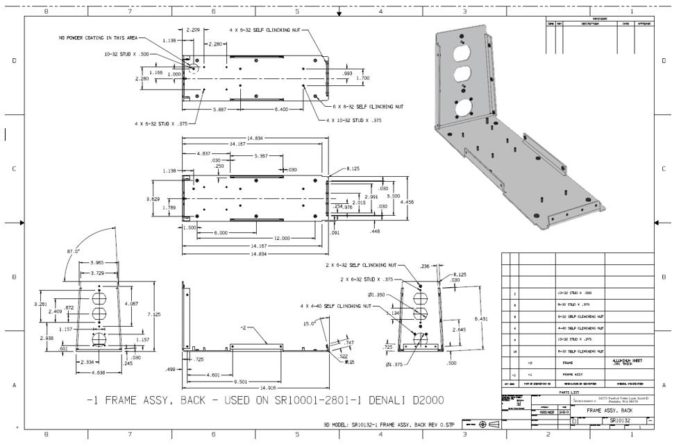
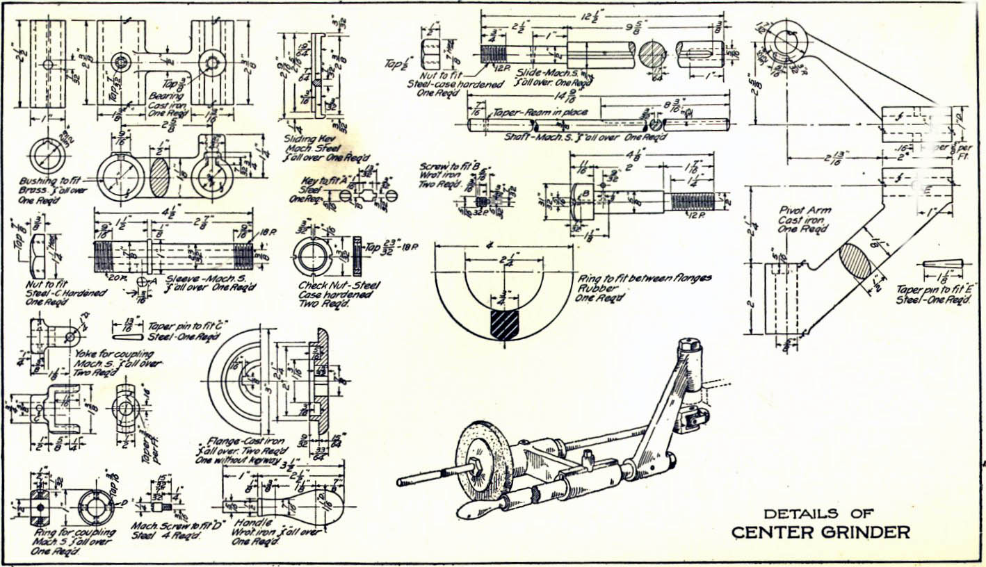
Here is and ancient example of a detailed
assembly.
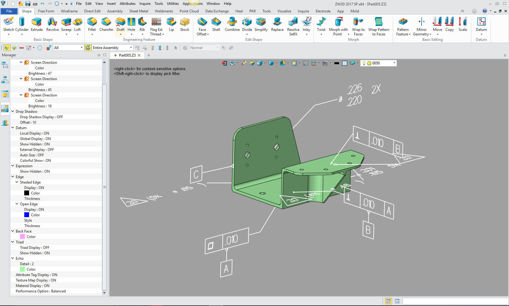
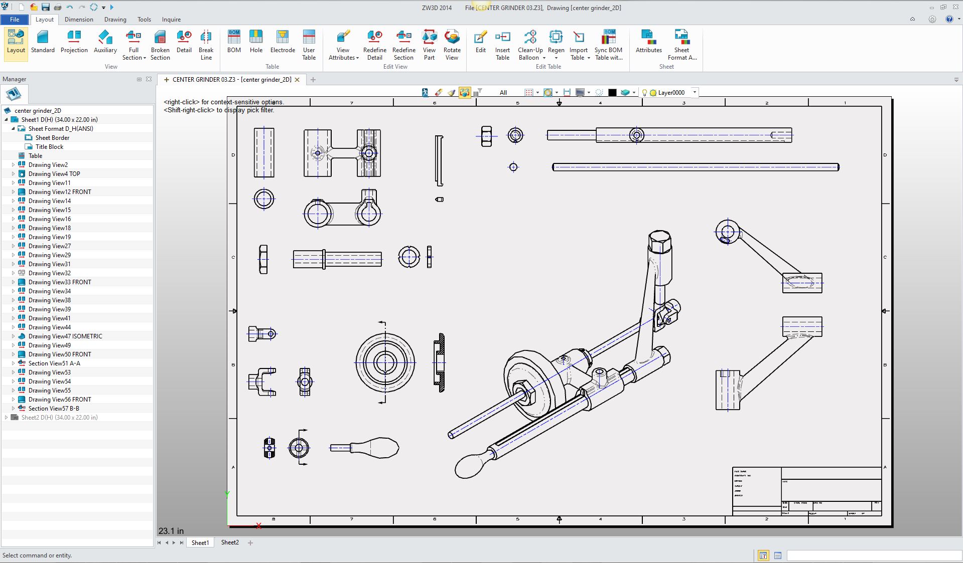
Here is the converted 3D CAD assembly
presented as an AID sans dimensions. This AID was set up in minutes.
Detailing would take an hour or two. But with the documentation
advancements of today we could easily produce much better
presentations than trying to duplicate a century old standard. But
this would take a complete knowledge of basics of that standard.
But to completely correctly detail a part it
takes drafting knowledge and skill. This is where I believe we need
to teach the 3D CAD engineer to make actual manual drawings. I would
probably do it on the board with the different drafting tools. It
will give them a good hands on feeling of the basics. It take much
less of a learning curve than training on an electronic drawing
package such as Autocad. No, of course, we do not train to the level
of the past just a good understanding of the process. When they
create the drawing with the orthographic, section and detail views,
they will be able to read a drawing. Reading a drawing is the
ability to see the part in 3D by reviewing the drawing.
It wouldn’t have to be a long class one good
semester. Each engineer would understand how things are laid out.
Remember this is not only for creating documentation for
manufacturing, but also to understand the thoroughness required for
good design engineering. Today the 3D CAD engineers are doing peer
checking. Which in many cases can be the blind leading the blind?
Every large engineering group needs a dedicated checker. Who is responsible for the correctness and completeness of
the parts. To consider checking as nothing but an overview for
obvious errors is a recipe for disaster in incorrect parts and
slipped schedules. It is always the small error that can cause
disaster.
We would need to follow with a class of 3D
CAD design. After learning the basics of 3D CAD and with the ability
to read a drawing, they can now start creating parts from sample
drawings. Not only does this give the student different challenges
with the CAD system, but exposes them how parts are designed and
defined. Thereby giving the student a hands-on introduction to 3D
CAD design and engineering with an emphasis on KISS (Keep It
Simple Stupid)
Engineering Ignorance Defined IV
Defining the
“2D Drawing”
Redundant? Of course!
Educating the PLM Guru!
I suggest any school adopt Onshape. Not that it is the best 3D
CAD system, but it can easily be used to create parts from drawings.
It is free and resides on the cloud, so they can work on it
anywhere. PC or Apple.
I am sure this would go hand in hand with the
basic understanding of classic engineering. With the 3D CAD they can
be introduce to all of the CAE with simulation functionality.
So, there you go. We now have well rounded 3D
CAD engineer ready to relate to a real engineering environment and
ready to go to work.
Update 4-3-18
As I review this article I realize there is
little or no drafting or documentation training available today for
the 3D CAD engineer or AIDs from models. It has to be folded into the college courses.
If not, the engineer is delivered to a strange world of dimensions,
annotation, form, fit and function design and even a new CAD system.
They have to learn this before they can be effective. Sadly, this
learning curve is fraught with many pitfalls causing errors and
slipped schedule depending on the haphazard way it is introduced.
If you would like discuss options about
setting up a functional curriculum on this subject in your company
or school, please give us a call.
TECH-NET Engineering Services!
We sell and
support IronCAD and ZW3D Products and
provide engineering
services throughout the USA and Canada!
Why TECH-NET Sells IronCAD and ZW3D
If you are interested in adding professional
hybrid modeling capabilities or looking for a new solution to
increase your productivity, take some time to download a fully
functional 30 day evaluation and play with these packages. Feel free
to give me a call if you have any questions or would like an on-line
presentation.
|