 The Death of the Drawing The Death of the DrawingIt has taken almost 20 years for me to truly understand this situation. Update 7-14-15 After a few discussions on this subject I realized that I could make it a bit clearer. A drawing is not based on a the 3D CAD model. So if I tell you I am going to send you a drawing you will know that it is a document (PDF) that is not based on a 3D CAD model. Below I define the AID (Associated Information Document) as a document (PDF) based on the CAD model. If I say I am going to send you the AID you will automatically know that a CAD model will be included. There are a few in the industry that are still designing with the electronic drafting packages and creating drawings. Many fabrication companies have not moved to 3D design. The 3D model, like with sheet metal or machined parts, is not necessary for the fabrication of many parts that do not require CNC or where it may be impractical.
New related Article Ref: Can Engineering Survive without the Drafting Group? The Drawing What is a Mechanical Drawing? "A scale drawing of a mechanical or architectural structure done with precision instruments." Now this article refers to Industrial/Mechanical Engineering only. Not Architecture, Civil or HVAC.
Ref: My First 17 Years or "How did we do it without 3D CAD!"
Ref: The 1980's - 3D CAD - The Beginning
Ref:
The Death of the Draftsman or “Where has
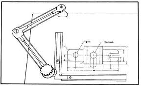
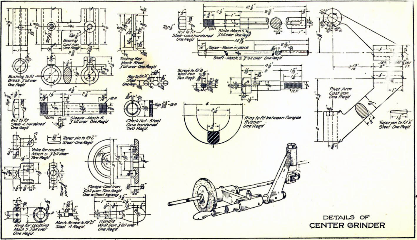
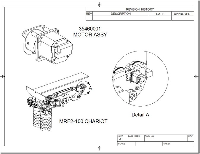
all the talent gone?” To call these drawings 2D is a bit of a misnomer. These were schematics or illustrations that described parts, notice I didn't say 3D part, that would be silly and redundant. They were done to a set of standards developed over centuries. An engineer or drafter would look at these drawings and see the part. This was called "being able to read a drawing". Now don't discount the drawing, virtually every Boeing airplane from the 767 down were done only with drawings. Drawings contained all the necessary information for manufacturing to make the part. They were released to the other departments in the company as copies called blue prints. Here is an example of an old drawing. I like it because all of the parts of the assembly are drawn on the same sheet. This was called a detailed assembly. Can you imagine a PLM expert trying to handle this information?
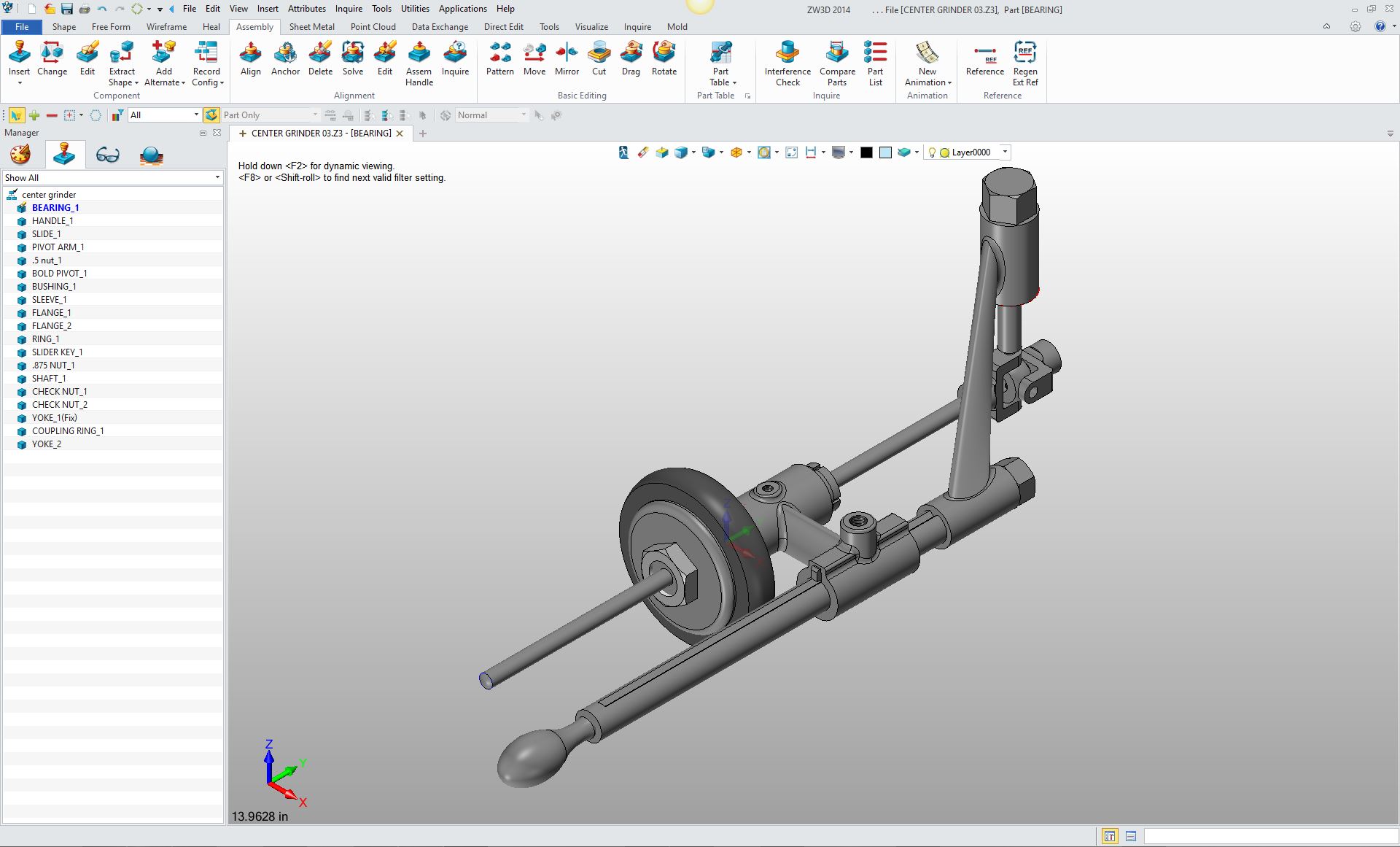
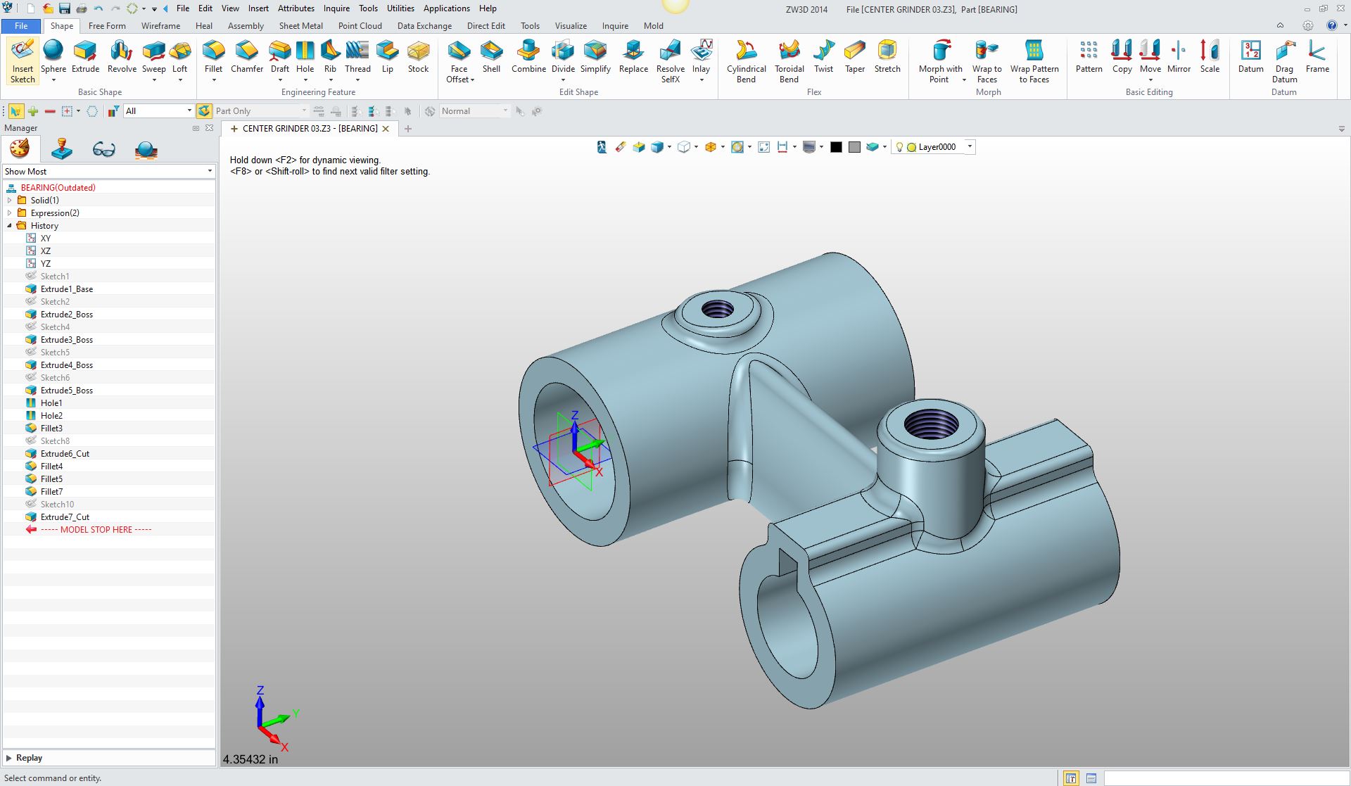
We do not do drawings anymore! Hey, wait a minute what are you talking about all of the CAD systems have drawing modules to do the drawings!!!! Enter 3D!!! So, do we create drawings as described above? Of course not, in the drawing or better called the "documentation" or "AID" module we create views generated from the solid model. Then we add the dimensions and annotation. We are surely not creating drawings. Well, they look like drawings!!! Yes they do and that is where the problems started. AID (Associated Information Document) This is what I have coined these 3D CAD generated documents. At Boeing they were called the "Flat Files". Here is the solid model of the above assembly done in ZW3D.
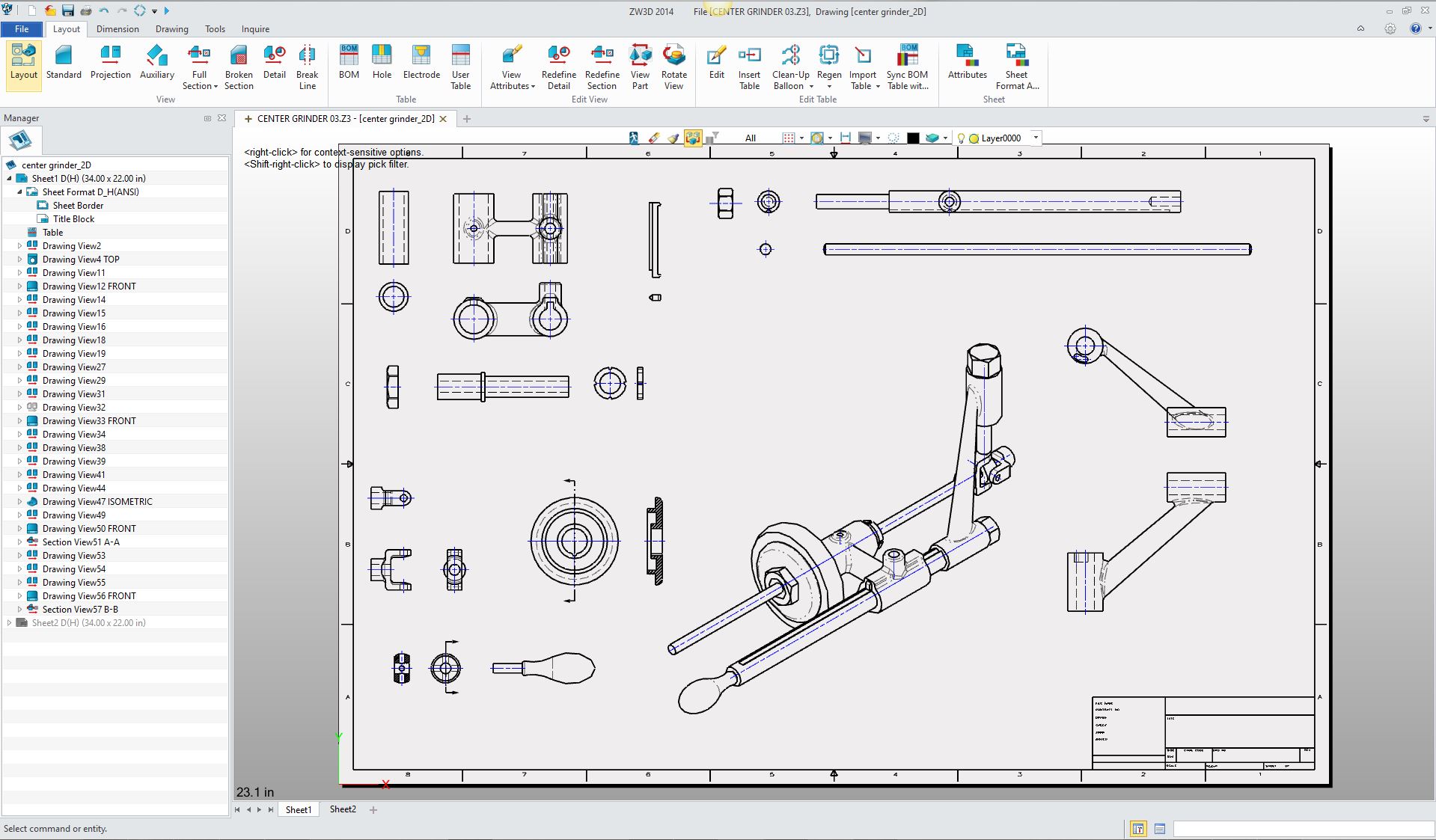
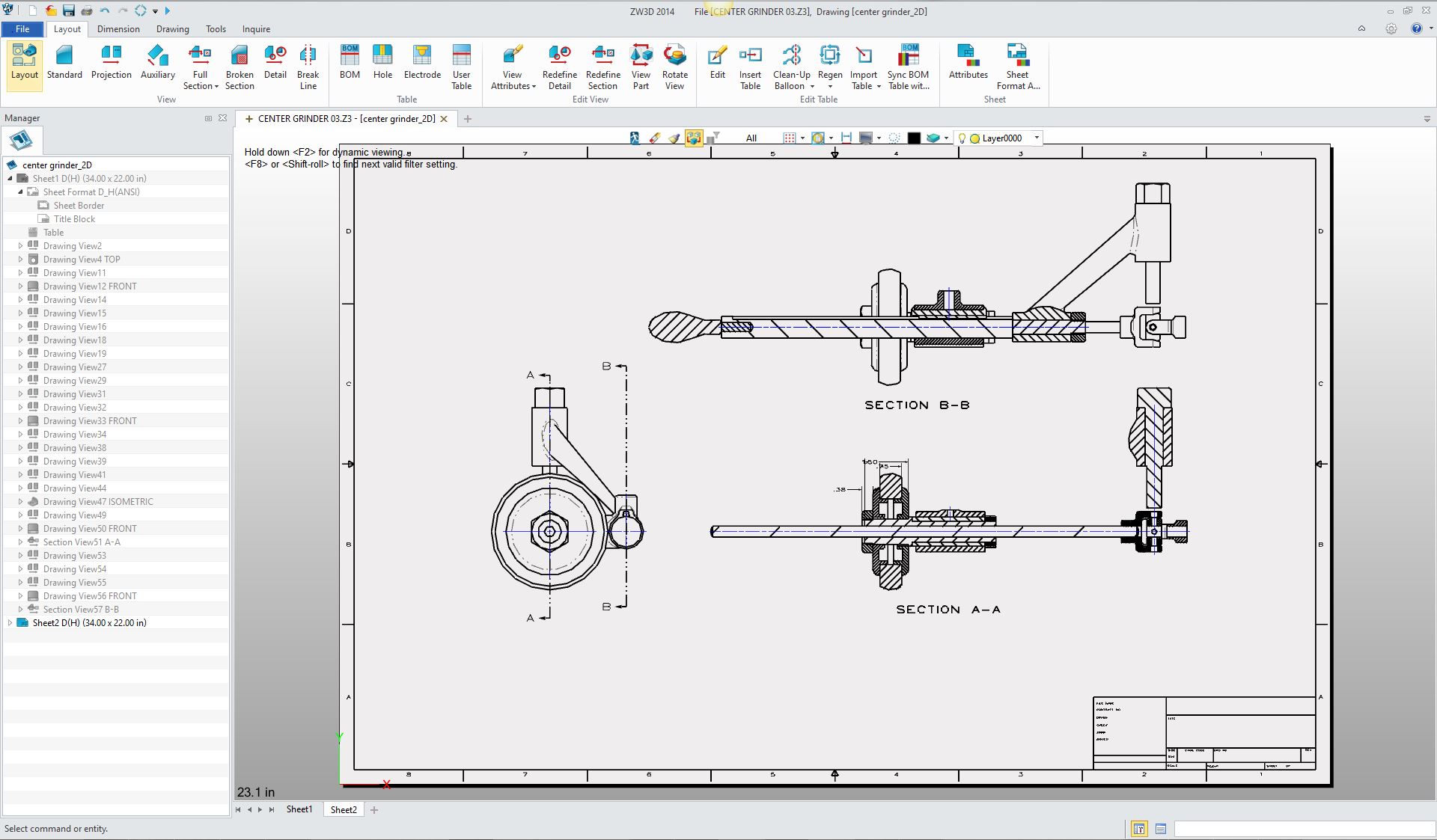
Here is the AID of this assembly. Every view here was generated from the model and took only minutes to create.
Sheet 2 Section views created automatically, no drawing here.
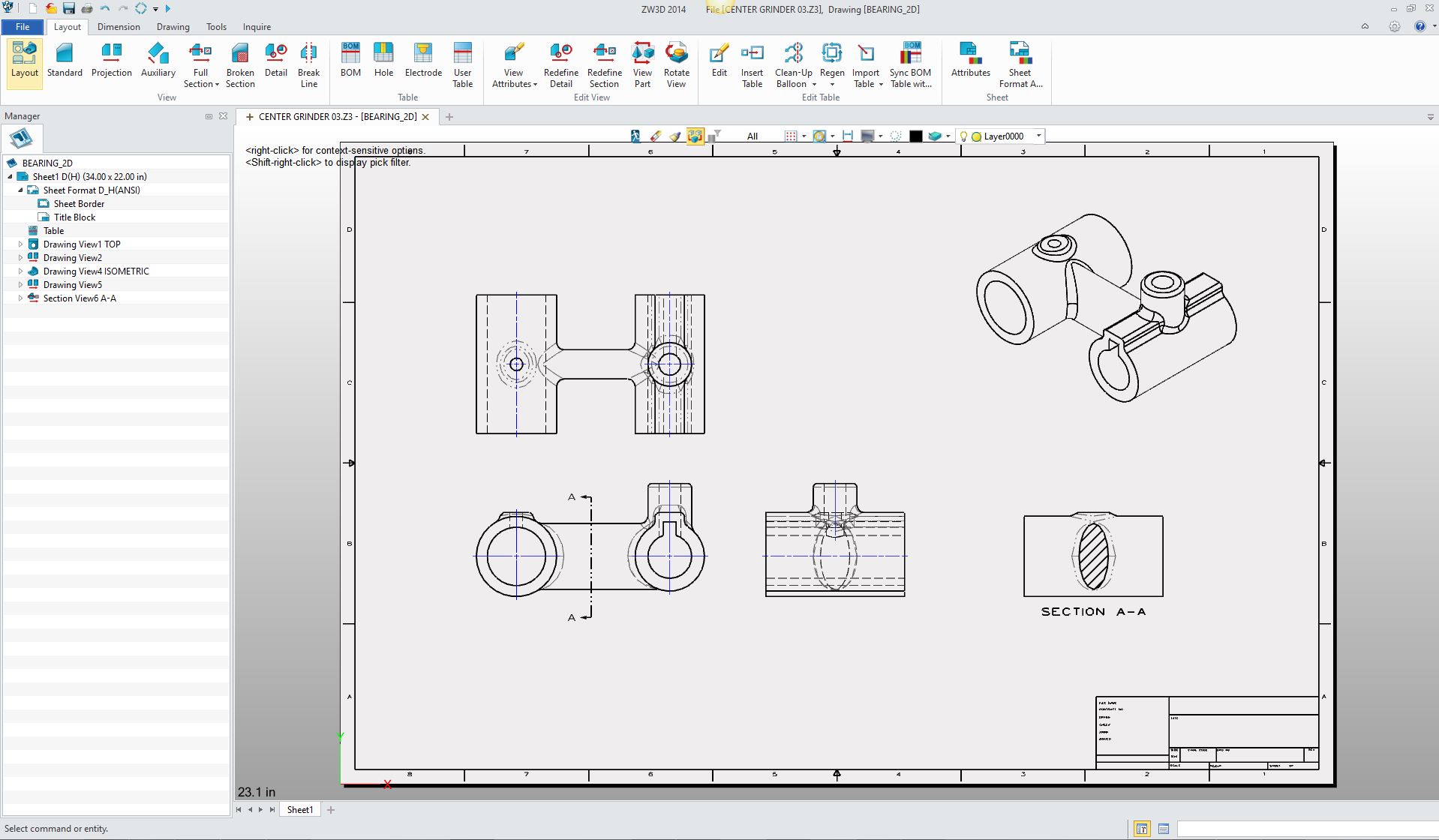
Here is an AID of the Bearing. Nope, not one line drawn!
Did I draw the above documents? Of course not! So why are we still calling them drawings. Small matter? Not really, it has confused the industry. Many engineers have never done a design as a drawing, creating the separate orthographic views, manual or electronic. These again are AIDs (Associated Information Documents), I cannot make this point clear enough, generated from the 3D model. We do not do drawings or layouts we now design the parts directly in 3D. Layout: A special drawing, only presenting the part or assembly design done by an layout or board engineer or design draftsman. Very few tolerances. Given to the drafting group to create the standard engineering drawings. The bearing
I started in 3D CAD in 1982 with Computervision CADDS 4, it was a 3D wire frame system. I have never done a "drawing" in CAD. I have never used Autocad or any other electronic drawing package. CADDS 4 had an "AID" module and we would take the views of the 3D wireframe and detail them. We would have to blank, trim or change the attributes of any affected entity to produce a good AID to duplicate a "drawing". CAD was in the realm of the drafter in those days. The AID, as a print, was the deliverable along with the 3D model as the 3D wireframe, surfacing and solids were developed. Engineers would sit with us and review concepts together. I would like to blame Pro/e (engineer) for bringing the engineer on board, but it happened in 1983 while I was on contract at Solar Turbines in San Diego. They let all of the direct draftsmen go and brought the engineers on to CADDS 4X. I was the last contractor left to train them. They resisted but Solar said learn the CAD system or you are fired. They moved to CADDS 4 and became very good CAD users.
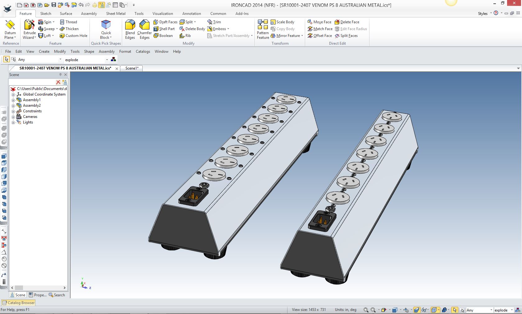
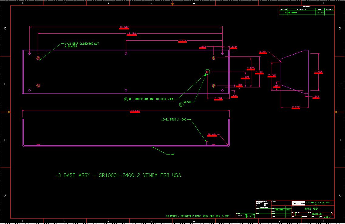
Today we design parts directly. But we still need to have the information for tolerancing, material, finish, processes, etc. The AID is a very easy document to create . It is a format that includes all of pertinent information. It is tied to the solid model so any changes will be shown. You can keep a history described in the revision block. It is an easy to review, there by having a document to check the design. It also serves as a second check for the designer. Here is an example of how a design change is marked in an AID. Here are the two concepts. I had to rotate the receptacles which required making the power strip wider.
Here is the AID of the base. Notice that the affected dimensions are highlighted. They can easily be reattached or recreated.
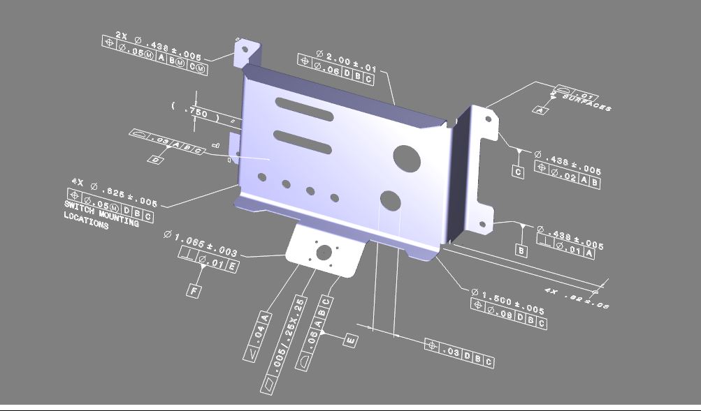
Enter MBE (Model Based Enterprise) and the PMI (Product Manufacturing Information) I remember getting calls from my Boeing supplier customers asking what they should do. Boeing was just sending the solid model and they did not provide an AID to inspect it, they were sending the native model with PMI. Most did not have a seat of Enovia or Catia 5 to view it. I provided drawing services for a year or so until they got the CMM and CMS equipment to inspect the parts to the solid model.
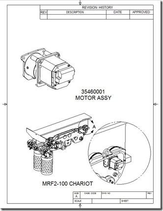
Ref: Free PMI Importer? Beyond Duplicating the Conventional Drawing Today's drawing or documentation modules can deliver much more in the form of communication graphics than just dimensions and annotation. They can deliver complete documentation functionality. Here are some documents created in IronCAD. We can put the model in virtually any format and add any type of annotation we want. Beyond engineering we can use this for planning, marketing, Tech Pubs, Illustrations, etc. Ref: Leverage Your Engineering Data - Sales, Publication and Marketing
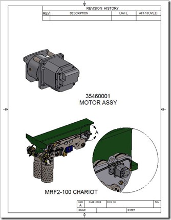
You can use the documentation format to create more precise and clear technical documents.
Or Horizontal.
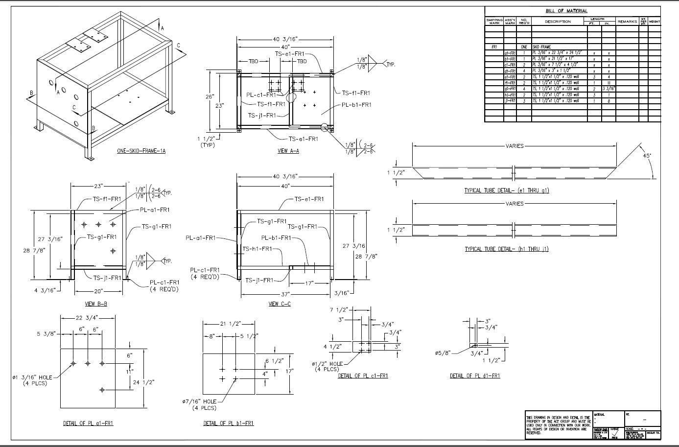
So to look at only creating views with dimensions and annotation is only scratching the surface of what kind of documents we can produce today!! No not on paper, delivered in a standard PDF or other graphics format. Conclusion: If you are 40 or younger it means you have been in CAD less than 20 years. That was 1997. Pro/e, Catia and UG were getting ready to move to the PC. CADKEY, SW, IronCAD, ZW3D and SE were well in place as solid modeling packages. Autodesk Inventor was just around the corner. Ref: The 1990's - 3D CAD/CAM Moves to the PC!! Ref: CADKEY or Catia? Boeing’s Billion-Dollar 3D CAD Mistake! From Drawing Based to 3D Based Example Some may have been stuck in Autocad making drawings. But none were still on the board. A while ago, I gave a presentation of IronCAD to a company that was still using Autocad to make drawings. They built welded assemblies and did not design any machine parts and were satisfied with creating drawings since they were basically doing component design. I actually created the frame assembly in front of them in less than an hour and created the AID's including an ISO view of the assembly within minutes. Showing them the speed of solid modeling. Here is the original .dwg. I did not use the .dwg graphics in creating the model. It was made of square tubing and I just created one tube and copied and pasted them into position and pulled them to the correct length and trimmed if required.
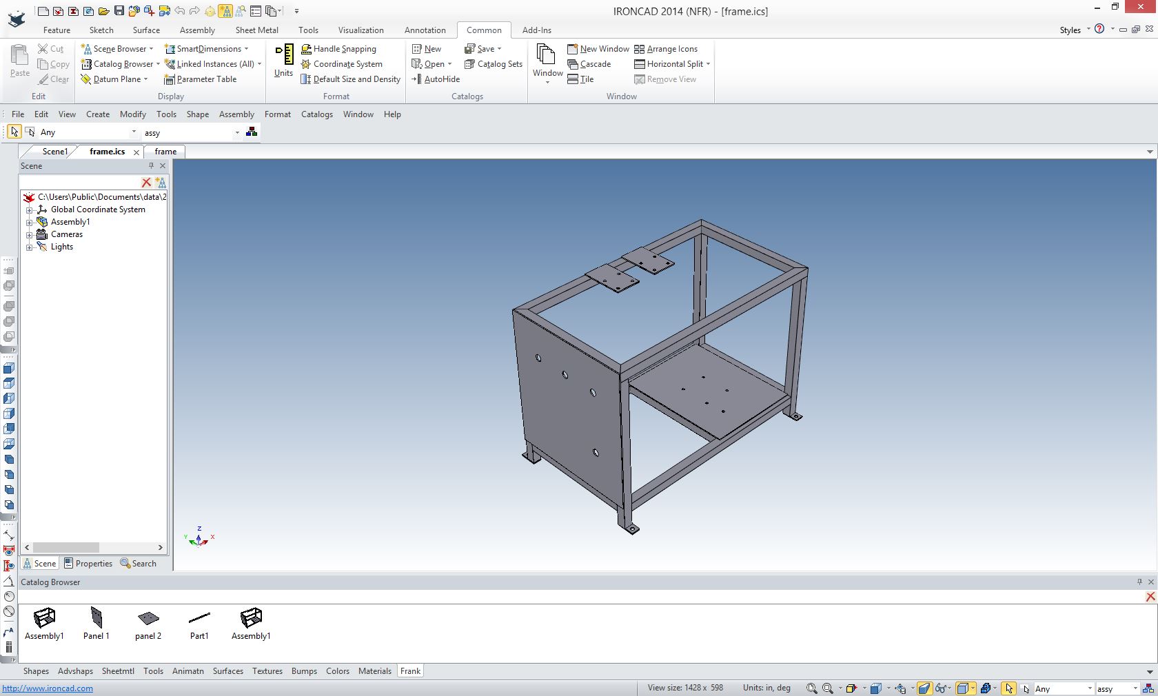
Here is the assembly created in IronCAD. Notice we created a custom catalog (bottom) with some of the common parts.
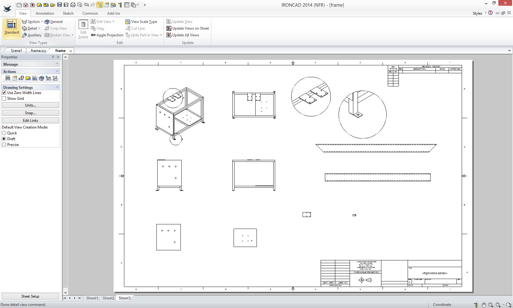
Here is the AID sans dimensions and parts list.
So the future is here. We do not create drawings. It is time for us to quit using a term that describes a very tedious process that is rarely used in our industry today.
The Death of the Draftsman or
We sell and support IronCAD and ZW3D Products and provide engineering services throughout the USA and Canada!
If you are interested in adding professional hybrid modeling capabilities or looking for a new solution to increase your productivity, take some time to download a fully functional 30 day evaluation and play with these packages. Feel free to give me a call if you have any questions or would like an on-line presentation. For more information or to download IronCAD or ZW3D Joe Brouwer206-842-0360 |

HOME | ABOUT | PRODUCTS | SEMINARS | TRAINING | TECH-NET NEWS
TECH-NET ASSOCIATES | RENDERING OF THE MONTH | CAD•CAM SERVICES
HARDWARE | TECH TIPS | EMPLOYMENT | CONTACT