Redefining 2D/3D
 There has been a battle in engineering between 2D and 3D since CAD started. The problem is that we have a misnomer. There has been a battle in engineering between 2D and 3D since CAD started. The problem is that we have a misnomer.
When I was a young drafter at Boeing in the 1960’s I never got up in the morning and said, “I am going to work and create a 2D drawing”. So, what did I do? I created graphic representations on paper or Mylar of a real life or “3D part” using separately drawn orthographic views.
The first thing they did with a young engineer at Boeing was to put him/her on the drafting board to learn drafting skills under the guidance of the drafting group. Drafters and engineers had to be able to look at the drawing and see the part in 3D and if you couldn’t do that you were probably pushed off into management. Even architectural drawings represented real life 3D by just including an elevation view.
 Pre-CAD the only thing that was visually 3D was an illustration done by “Illustrators”. Boeing and most large companies had large graphic arts departments that produce illustrations. All types of manuals were created, things that now take a push of a button, used to take hours and hours to produce. You could say Da Vinci was one of the first illustrators. I suppose the scratch illustrator was the first to go as solid modeling moved in. We now just use a screen shot of the 3D object. Pre-CAD the only thing that was visually 3D was an illustration done by “Illustrators”. Boeing and most large companies had large graphic arts departments that produce illustrations. All types of manuals were created, things that now take a push of a button, used to take hours and hours to produce. You could say Da Vinci was one of the first illustrators. I suppose the scratch illustrator was the first to go as solid modeling moved in. We now just use a screen shot of the 3D object.
The Death of the Draftsman or
“Where has
all the talent gone?”
The Death of the Drawing
Engineering Ignorance Defined IV
Defining the
“2D Drawing”
Redundant? Of course!
Say goodbye to the terms 2D and 3D.
Drawings from scratch take a high level of knowledge to produce a complete description of the part. Solid Modeling is very easy and opens the door to producing parts that are not optimum or may not even be manufacturable. There is an acronym used in the industry today, DFM (Design for Manufacturing). I would love find out what the situation was that caused folks to create this acronym. If I said this to the engineers, designers and design draftsmen of the past, they would give my a strange look and say:
"What else would you design for?"
We can extrapolate partial or complete AIDs (Associated Information
Documents) from the model in all documentation modules that are
available in all 3D CAD packages. Yet this is even found too difficult. The completely
defined AID offers much more to the designer than what appears on the surface.
Enter Autocad – 2D is a Drawing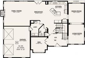
So why start with Autocad? Heck, I had been using 3D Computervision CADDS 4 since 1982 and Catia in 1986 was also 3D wireframe with surfaces. But what was being created in Autocad? “SCATCH DRAWINGS”. So let’s go back to the definition of a drawing above and with that definition Autocad should have been call a “Computer Aided Drawing” Program. Hmmm CAD. But we all know that CAD means “Computer Aided Design”, or did it? CADDS - Computervison Automated Design and Drafting System
So Autocad wasn’t really a 2D program it was a Computer Aided Drawing Program. So there really isn’t any 2D design it is basically an electronic drawing package that creates drawings that are again graphic representations of real life or 3D parts. So we use the word 2D to describe creating parts by views that describe the actual part. So when you are designing by drawing views you are designing in 3D.
Enter Solid Modeling – A Solid is 3D
This should have been called 3D Drafting!
I am going to skip the history of CAD here but you can see another Article with the history included if you are interested.
The 1980's - 3D CAD - The Beginning
By the late 1990’s solid modeling was well in place. We know all the products. We still created drawings, notice I didn’t say 2D drawings because that would be redundant. But instead of drawing the views we would create instances of the part in different orientations in a separate part of the program or an external module that was specifically design to create AIDs or other documentation.
The 1990's - 3D CAD/CAM Moves to the PC!!
At this time CAM (Computer Aided Manufacturing) using CNC (Computer Numeric Control) could take a surface or solid model and create programs that would drive the 2 or 3 axis mills. They would use the AIDs (drawings) only for inspection. Soon someone said “Why make AIDs (drawings)?”. Now this does sound like a obvious question.
Today we do not make drawings!
A drawing is a document that is done on the board or an electronic drawing package like Autocad. Each view is drawing with lines, arcs and curves. Each view is separate and if a change is made each view has to reflect that change. Lots of work.
What do we make?
AID (Associated Information Document)
No we do not create drawings. Like I said above we just create instances or views of the 3D model and detail and annotate them. This hardly creating "DRAWINGS". So we have a horrible misnomer that is confusing the industry. AID's are very simple to create and can be done very fast. They look just like drawings and that is where we get confused. We could reevaluate this process and create a different standard which is much more conducive to the simple process of placing views and detailing them.
The selling
point of 3D CAD was to create the AID (drawing) or documentation faster.
From Computervision, Catia to Pro/e that was the purpose. The AIDs
(drawings) were printed and treated just like a manual drawings. Soon
with the introduction of CNC we started sending the 3D model with the
prints. It wasn't until the wide use of the PDF at the turn of the
century did we start sending our engineering documentation by email.
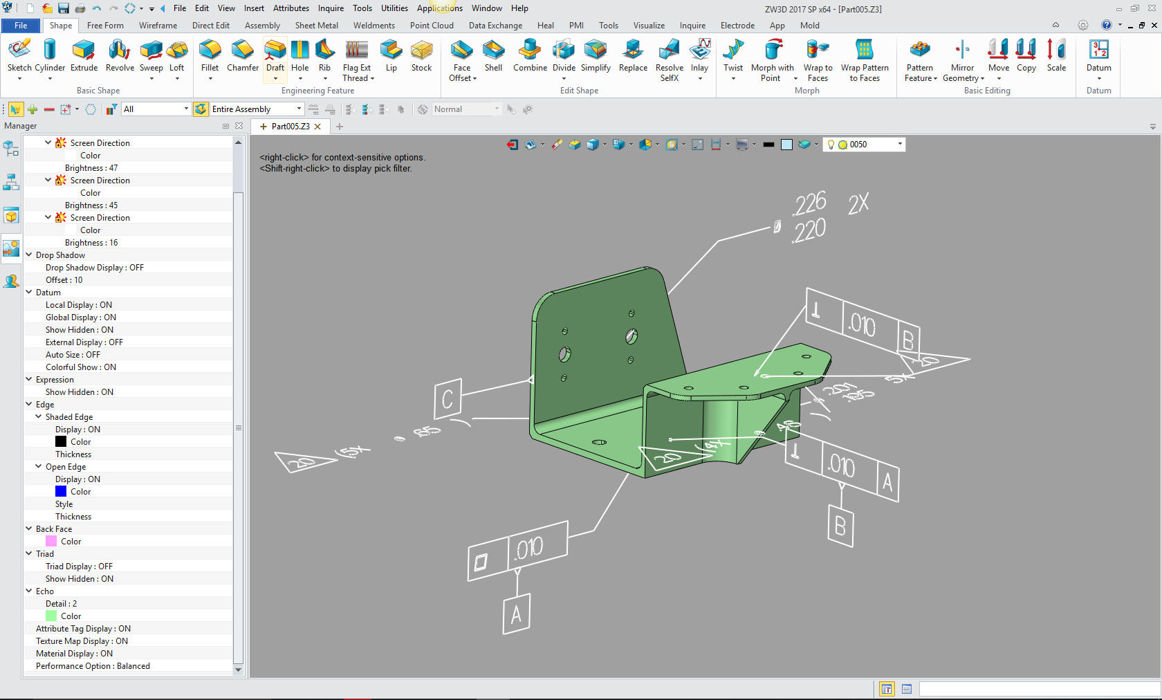
Today, there is a movement to include the GD&T inspection information directly on the model in 3D space as shown below. Boeing has adopted this process, but still includes separate documentation providing critical information. It truly has been a failure. Why not just create the AID?
The Death of the Drawing
Compare and Validation Programs? Band-Aids for Self Inflicted Wounds!
Do we really need AID's?
Read this article: To Draw or Not To Draw!
That obvious question is now being answered no. But, we still need to supply tolerances for the parts. We still need part manufacturing information, such as material, finish and other requirements. The solution was annotation in 3D space. As you can see below this is all the standard drawing information in the parts 3D space. The problem is that this data is not a standard. It is sent out as a native part format and you have to have a program that will read it. But look at this below. It is confusing on a simple part. Just imagine on a very complex part. Not just the confusion in reading it but imagine the poor engineer (now that engineers are now glorified drafters) or drafter that has to do it. It really must be a horror show.
The Death of the Draftsman or “Where has
all the talent gone?”
Educating the New 3D CAD Engineer - 2015
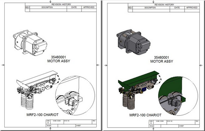
You tell me which is more clear and easier to understand.
PMI (Product Manufacturing Information) in 3D space.
After a bit of investigation I believe the PMI was developed to eliminate the AID delivered as a "print" along with the 3D model. The PMI was developed before the PDF became widely used. I really doubt if there would have been a need for a PMI if they could deliver the AID as a PDF. Of course, now we even have 3D PDF. But there are 3D CAD systems that have the documentation integrate with the part or assembly. Would we even need the PMI if we would have standardized on one of these packages? It truly is time to rethink how we deliver our engineering documentation.
Why MBE/MBD/PMI Will FAIL
Why MBE/MBD/PMI Will FAIL Part II
I still hear people talk about paper, after 17 years?? Check out these
articles.
PTC Creo Totally Misunderstands MBD
Solidworks Totally Misunderstands MBD
But we still need to know how to detail and present GT&D information for inspection. The
PMI format is very hard to utilize in checking and reviewing the design.
One problem is if you don’t have the native software, you will need a special viewer to look at this data. But you really can’t separate the data and really get a working view or print. I only know a few programs that can view this data, Enovia (the Catia viewer) and Acrobat 3D (which is now some other program). If any of you know more please send me the info. I am more involved with Catia because so many of my NW customers use it or have to communicate with Boeing.
Note: ZW3D can read
NX, Catia, Creo and Solidworks PMI.
Free PMI Importer?
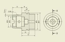
Below i have created an AID from the above Catia part. Which one is more clear. I can send the model in a STEP format and the AID as a PDF and anyone of you could start working. This is, of course, if you have direct edit functionality available. I can also send you the native Catia 5 file. How many of you could read it and see the PMI? Not many, would either format be superior? No, they both deliver the same information. My point made.
So
why not just create the AID???
Compatibility - Universal CAD Compatibility is Sorta Here!
With the introduction of direct editing as a optional CAD procedure most CAD systems can now read other CAD programs solid models and work with them as if they were created natively. The problem is that the drawings are not transferable from CAD system to CAD system. There are only three programs that have integrated drawing capabilities and the drawing, part and assembly are in the same file. This is where the concept of the PMI data came. But as I said above you still have to have compatible software that can read the native file of the originating CAD program. This concept is only in a few of the high end CAD package nowhere close to any form of a standard.
The Integrated Drawing in 3D CAD
Note: As I
researched the direct edit functionality in the Pro/e (Creo) clones I
found that the face moves was an added step in the history which made
the part history unusable.
We need a standard.
We have made a mess of PDM (Product Data Management) and PLM (Product Lifecycle Management).
So how do we do this without specialty software.
A Simpler Solution -
The Embedded Title Block! A PLM Solution!
Most CAD package can create solid text and emboss or imprint the part name, number, revision, website and phone or contact information in a part. This virtually solves the problem. This really relates to large companies that have heavy use of outside suppliers, but could easily be a standard for all parts.
I envision a Web page for each part or
assembly. This would be done by the document control group. Utilizing
the release package or bundle from engineering.
This would be the only source for the part or assembly.
What would it include:
-
All of the specifications
-
The latest changes included in the current revision.
Immediate notification of changes.
The history of the prior revisions.
Checking out the latest solid model in a variety of formats.
You can go to look at 3D Content Central for a reference.
Recording of who downloads parts (Password Permission of course)
Automatic notification of any change in status of the part.
All engineering would look here first then continue to access the affected native parts.
Would we include an AID? Of course, now that we have the web page the only authority. We can easily have a PDF available for download for inspection purposes. Probably only defining the mating features.
Who would use this web page.
This is just too simple.
Update: 10-23-15
We now have this
solution.
Standard Cloud Based Engineering Document Control
Standard Cloud Based Engineering Document Control
Part II
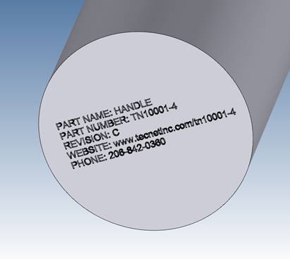
The Embedded Title Block Defined!
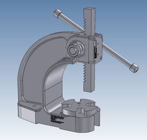
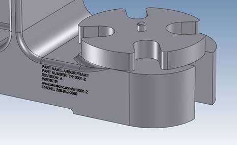
Take a look at this concept. INOVATE is the tool I am using here but I am sure all of the major programs can do this. The part is then be put up on the internet. I comes with enough pertinent information for anyone to make sure they have the latest version. Of course this is mostly for those companies that have many outside suppliers. The data could include the following and embossed or engraved in the part.
Part Name:
Part Number:
Revision:
Website:
Phone:
Since I started my engineering career at Boeing in 1965. I know a bit about how the drawings were done and distributed. In the beginning we worked with blue prints. Yes actually they were white on blue. We had blue print counters throughout the plant. Then I left the industry and came back in 1975, now there were microfiche, we could now get all of our drawings on a card and print the parts lists. I could take hours and hours to research to fine the correct configuration.
Website: I am sure now there is a webpage for each part and assembly. Where you can see the latest revisions and status of the part. You can download the part or assembly if you have permission. Outside suppliers can log-on to get the necessary data and be on a special list to be notified in case the part changes. Now again this is for large companies that use outside suppliers.
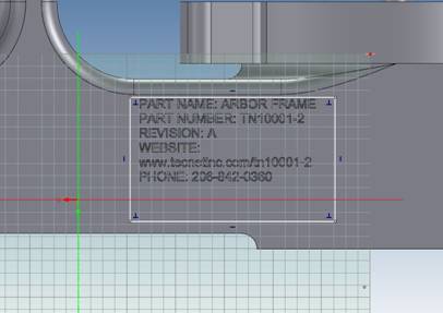
Here are a few examples of having a part mark on the part itself. You would put in on a easily modified surface. INOVATE makes this easy. You just drag the base text from the catalog, edit it, size it with handles and subtract or add. You can how the text can be sized below.
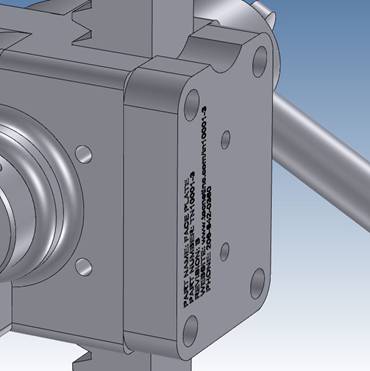
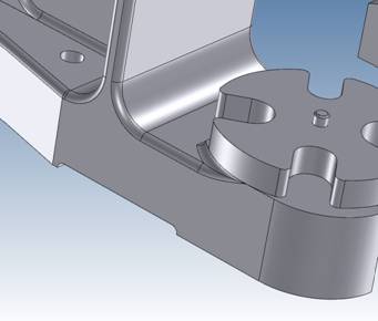
Most
CAD systems can modify the part to eliminate the part mark to have a
clean machineable part. This is where a history based system has an edge
on direct editing. You can just suppress the covering extrusion. With
direct editing only products you have to have two parts. Luckily
IronCAD/INOVATE and ZW3D have both History/Feature based and
direct editing functionality integrated in the program.
The CAD products I use is IRONCAD/INOVATE or ZW3D. Both can easily create the text in the solid model.
Most of the above graphics are generated from IRONCAD. Are you tired of the sketch, sketch, constrain, constrain, painful way of CAD design? Take a look at the most sophisticated CAD solution available. The basis of engineering is creating parts and IRONCAD/INOVATE can just do it easier and faster. CAD does not have to be complicated. Give IRONCAD/INOVATE a try go to this link to download a 30 day fully functional evaluation, including all the translators.
Is 3D CAD Productivity an Oxymoron?
3D Modeling Techniques Defined
It is easy to load and get up to speed. It
includes all the translators so you can get started seeing the
advantages of implementing the power of INOVATE or IRONCAD CONNECTIONS.
You can directly access your existing engineering data. Take some time
to get the other departments involved. This truly is the solution to
make each person in the company access to all the engineering data and
in the know.
There is much more to these products take a look at the
Comparison Chart
TECH-NET Engineering Services!
We sell and support IronCAD
and ZW3D Products and
provide
engineering services throughout the USA and Canada!
Why TECH-NET Sells
IronCAD and ZW3D
| If you are interested in adding professional hybrid modeling capabilities or looking for a new solution to increase your productivity, take some time to download a fully functional 30 day evaluation and play with these packages. Feel free to give me a call if you have any questions or would like an on-line presentation. |
For more information or
to download IronCAD or ZW3D
Joe Brouwer
206-842-0360
|