|
The above image is the AID (Associated Information Document) generated and detailed from from the Catia 5 PMI part file referenced below! This is "not" a drawing!
Update 3-9-20 Can Engineering Survive without the Drafting Group?
Update 10-7-19 As you all know I am always pondering on the state of engineering today. I always chuckled at the concept of DFM (Designing for Manufacturability) and why it was even considered. You would ask any draftsman 30 years ago if they were DFM, they would look at you strangely and ask "What else would you design for?" But I realized we did design for something, DFD (Designing for Documentation). The end product of engineering is the documentation. You designed by drawings. The development drawing (The Layout) and of course the released drawing. We had many eyes on the part and assembly design. It was all approved by the signatures in the title block. The most important signature? THE CHECKER! He/she were the most knowledgeable. Without this hugely important position engineering is in the state it is today. Making sure the documentation is correct is the "Most Important Step in Engineering". It was done by the drafting group. Engineering is in the condition it
is today Boeing has created a "Producibility Group" to review the released documentation, which, of course, is a bit too late. There is no one today in engineering with applicable documentation process knowledge. I sadly watch as engineering wallows in its ignorance! Update: 5-6-19 As a design draftsman pre-CAD we would focus our design with the consideration of creating the drawing. I have these realizations because much of the drawing process was 2nd nature. I see today designing in 3D that the documentation is not being considered and ending up as a second thought. It is time for engineering to reprioritize its purpose to make available concise, complete and unambiguous documentation to manufacturing. Update: 10-22-15 Now that the draftsman is slowly disappearing, and the 3D CAD Millennial engineer is taking on the draftsman's responsibilities the transition seems to be working well with the smaller companies. The engineers, I have talked to, seem to be willing to accept these new responsibilities and are even proud of the work they do, completely detailing parts. I am still wondering what kind of supervision they are under. Do they have a lead engineer guiding the design? It seems they are doing peer checking. Engineer's Job Description - The Search for the Purple Squirrel
I suppose this will be the process until they finally set up a standard checking process. There will be many more worker bee engineers replacing the draftsman thereby reducing the opportunities to move into engineering management. Hopefully engineering standardization of documentation is in transition. Sadly, there are very few with the applicable knowledge to lead the way. Educating the New CAD Engineer - 2015 This is a shocking report on the state of engineering documentation today. It seems to not have a standard checking and review process. This would have never been tolerated in the past. Even when you have proven safeguard Mr. Murphy finds his way to wreak havoc. The drafting group supported engineering management, today they depend on PLM and the the CAD vendor. Engineering Documentation Today!
Detailing: Completely
dimensioning a part.
As for the large companies, they have strived to streamline engineering by adopting the unworkable MBE (Model Based Enterprise) concept. They are cutting corners on all levels. They now produce the PMI (Product Manufacturing Information) which includes the minimized bastardization of GD&T applied on different planes in 3D space. So the CAD engineers are not delivering concise, complete and unambiguous engineering documentation. The completely detailed AID (Associated Information Document (drawing)) gives the designer a second look at the design for errors or a more efficient design before release. I will tell you, if a part is difficult to detail, it will be equally or more difficult to manufacture. Sadly, it looks like engineers are now not in charge of engineering in these large companies. This has driven engineering cost sky high and reflected in the incorrect parts and slipped schedules. Hopefully engineering management will soon wake up and start taking control back from the PLM, IT and MBE proponents.
This is an article by Nikunj Patel and adds to my argument that MBE will fail as a engineering documentation standard. The Argument Against Model-Based DefinitionTO DRAW OR NOT TO DRAW??
I
remember when I first got into 3D CAD in 1982. It was 3D wireframe. After
working for awhile I said "boy, we will not need drawings any
more". Now, many companies are attempting to take that path. Creating an
associated information document (drawing) from a
model is very easy, even when complex it only takes a few
hours. We are now getting
models with only the features that need to be inspected defined. The rest are basically covered by
a profile tolerance.
This now being delivered in a format called PMI or Product Manufacturing Information, views in 3D with annotation added. This seems to be a solution requested by the PLM folks to only have to maintain one document instead of the solid model and an associated information document (drawing). Now this seems like a good way to cut design costs and get your parts manufactured. But there are problems. The below images are production Catia 5 files with PMI imported into ZW3D. This article shows how this large Airplane company is trying to implement this convoluted process. Unless you have the native CAD software, a native costly viewer, a expensive 3D party translator or ZW3D there is no way for you to access this companies engineering documentation. Please download ZW3D to be able to view the PMI from Solidworks, NX, Creo and Catia and actually modify the parts, easier that in the original system. PMI vs AID (Associated Information Document) 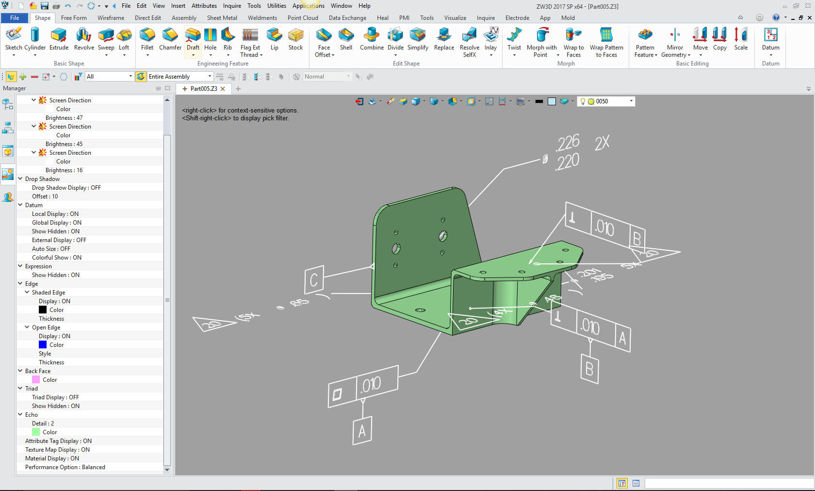 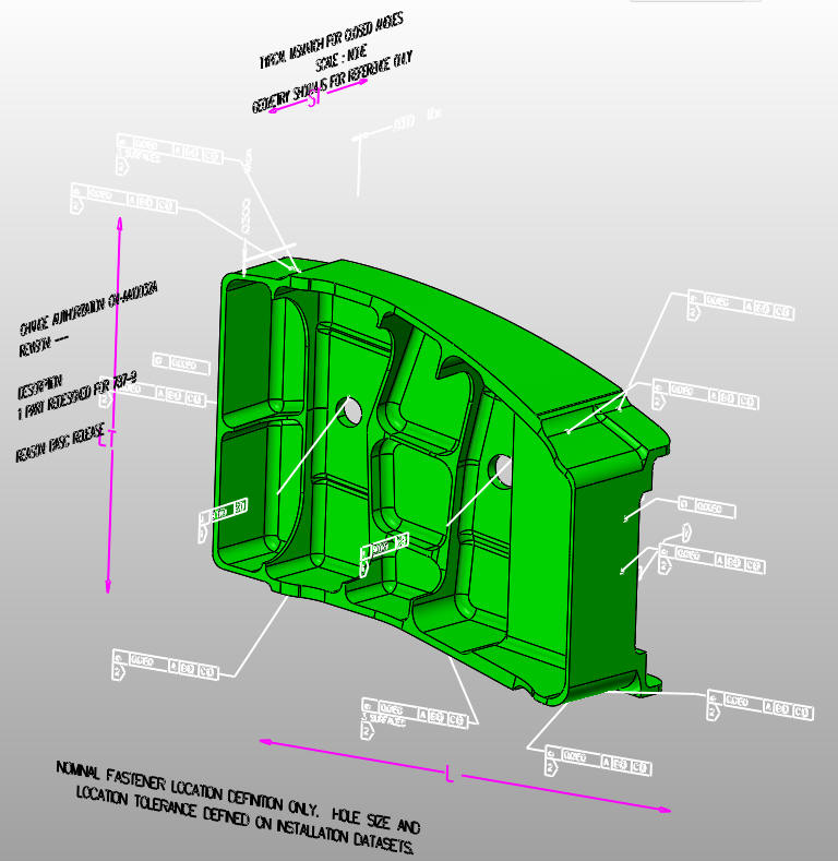 Redefining 2D/3D
DESIGN REVIEW
 We must now introduce the "AID
(Associated Information Document)" formerly fondly known as the
complete engineering deliverable authority "The Drawing". The
AID as a PDF is referenced to and travels with the 3D Model. We must distinguish the "Drawing" from
the AID. They are both handled very differently. The Drawing is a document using manual
or an electronic drafting package, such as Autocad, to create the different
unassociated orthographic views on a single plane. Many
"Drawings" are still created and must be maintained. Mostly used
for assembly schematics like panel placement and other
non-manufacturing information where little detail is required. The AID is created from views of the 3D model in an AIDs Module in the CAD package. This is very, very easy to create. Place the views and dimension the parts or assemblies, with a robust word processor for notes and other annotation. The AID is reference associated information delivered as a PDF with the 3D model in a native or neutral 3D format file. They are not the "2D Drawing". I hate that redundant term! I have taken jobs to make the associated information documents (drawings) from solid models for a couple of my aerospace customers. The original AIDS were delivered with just the GD&T, a step above a PMI, with a native UG part file. I really did not make a drawing, I created a AID (Associated Information Document) or what they called at Boeing the flat file based on the 3D model. I suppose we could call them prints, but they are delivered as PDFs or do they really qualify as prints only when they hit paper? I have never created an electronic drawing in CAD, I have only created AIDs. I started in 3D CAD in 1982!! 37 years ago. The 1980's - 3D CAD - The Beginning The Death of the Drawing While detailing these parts I could see that there were problems with the design. These 3D solid models are not being designed, they seemed to be created with very little thought or concern for standards by some CAD jockeys to basically fit. As you start to detail these parts you can see that there is not much rhyme or reason to the end result. The AID (drawing) defines what is important and what is not important. Now, of course, we do get some GD&T (Geometric Dimensioning and Tolerancing) in a AID (drawing) usually as a PDF. We now have two documents that have to travel together the solid model and the AID (drawing). Some systems like Catia have 3D annotation and other information included with the part, which is called PMI many with very little dimensional definition of the part. The new trend is to only include GD&T, having to have a CAD system to scrutinize the part. But very few programs can read the native Catia PMI file format so we may still have to have a separate AID (drawing) that goes with the model. There by creating the same situation of making sure both pieces of data are synchronized. Which leads to our next problem. Checking, Design Review, Manufacturing and Data Extraction! Free PMI Importer?
DATA VERIFICATION
Now that we
are attempting to use the model and not the drawing as the authorizing document, we seem
to have a problem keeping track of the data. When we had a
drawing we had something that was in stone. You could look and
say, "That has to be a .50 radius" and when it wasn't we had a
problem. Now we have model verification process, that compares
two models. No where does it say that the models are correct,
just that they are the same.
Of course we have a problem keeping the AID (drawing) up to date. This can be a bit time consuming, but you can check it on an AID (drawing) or check it at manufacturing after the part is made. Believe me a completely detailed AID (drawing) is much cheaper. The AID (drawing) allows you to scrutinize and allows more eyes on the design. As of now I am really not sure the procedure for checking and releasing parts to manufacturing. I am not in the design loop, but I am seeing what is being delivered to the vendors. It is not pretty. Some of the machine shops are sending parts back, saying that they can not be built. I can not imagine this happening in the days I was on the board. I remember working on the Manned Maneuvering Unit at Martin Marietta. I would take the drawings, after they were checked by the checker for fit and function and drafting standards to all the manufacturing , materials and stress engineers for review and sign off. At Boeing we would have design meetings with the drawings on the table. After seeing some of the parts coming out of engineering, I can't imagine how many of these parts being released. PTC Creo Totally Misunderstands MBD Solidworks Totally Misunderstands MBD The problem with AIDs (drawings) is that they take time to keep up to date. So no more AIDs (drawings), but the problems created without AIDs (drawings) seems to be worse. So now we need a CAD model verification program, that does not assure correctness. Update: Boeing now has a Producibility Group that reviews the design after release. I am not sure what happens when they find an error. Do they send it back to the original group? I can only imagine what problems with scheduling that would cause. Compare and Validation Programs? Band-Aids for Self Inflicted Wounds!
PURPOSE OF AIDS (DRAWINGS) TODAY!
So now we need CAD software to VERIFY the models and see the differences. This seems to be the unexpected consequence of eliminating complete AIDs (drawings). I have come to the conclusion the elimination of AIDs (drawings) are having devastating effects on our engineering process. So what is the purpose of the AID (drawing) in this day of "solid" models?
1. The original
purpose "To inspect the final part."
2. Ease of
design review, anyone can get a PDF and review the part design
and function. To see how the assembly of the parts affect each
other. No need for CAD experience or access to the CAD program or
viewer.
3. Absolute
authority for the part. A second check on the model.
4. A review by
the designer on any errors or design functionality the may have been overlooked. A chance to see if the design can be simplified or
optimized. I have had a manufacturer tell me that he has to
refuse some parts for lack of manufacturability. Even machine
shops have had to refuse some part because they could not be
built.
5. To teach new
drafters, designer and engineers how to design. They need to
have their designs scrutinized by an experienced checker, whose
purpose is to not only check fit, form and function, but to
impart his vast design and engineering knowledge and experience.
6. A history of
the design. Years ago we used the microfiche to review designs
of the past, today you have to have CAD software available to
access the data. I am not sure how we get to the data. With a
complete AID (drawing) you can recreate the part if necessary.
7. I am sure
there are a few more reasons, those above surely would save much
time and money as these parts are being delivered to assembly
and do not fit.
8. We need to move the engineering documentation out of the Native CAD system and deliver it as a 3D model (Native or Neutral format) and an AID. All release documentation would be managed by a document control group outside engineering. The Ultimate Document Control System
CONCLUSION
As I have said
before, to create an AID (drawing) from a model is very easy. Many of
the CAD programs will update the AID automatically. I
suppose that is the problem, the CAD software really doesn't do
a very good job updating the dimensions. But even then the
problems caused by the lack of AIDs (drawings) down stream, seems to me to worth
the effort.
Update: The Death of the Draftsman or “Where has all the talent gone?” Today, the millennial engineer is now doing the draftsman's job. Detailing a part is a time consuming and sometimes tedious process and engineers are not interested in doing it. Plus all of the form, fit and function design, investigating and fix any problems and revising and assuring these changes are recorded and maintained. Engineers have not been trained to do it and it seems that this lack of desire or knowledge has led to some peculiar solutions. The engineers lack of responsibility to establish a standard engineering process has left a void to be filled by the PLM (data management) and MBE (Inspection department) to create a process that fits their needs more than engineering's needs. Leaving the 3D CAD Millennial Engineer to jump through complicated processes, not realizing that PLM and Inspection should really be subject to engineering's needs. A bit like the cart before the horse. Sadly the draftsman, who were responsible for the standard engineering process in the past are being let go and being replaced by engineers with very little knowledge of the past standard process. The Engineering World is in Chaos. Where does your system stand?? The Worst to Best CAD System and Why! |