| Celebrating 30 years 1987-2017 Standardized Cloud Based Engineering Document Control 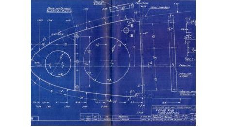 |
This article was originally titled:
The Ultimate Blueprint Counter
What is a Blueprint Counter?
I chuckled when I first posed this question.
Today’s young engineer may not know what a blueprint is. I can hear him/her now: “Why would they need a person or system to count blueprints?”
I searched for a “Blueprint Counter” on line and found a few images of cabinets. In fact, I searched on line for blue prints and after centuries of blue prints the above image was the only one relative to this article. Blueprints disappeared at Boeing Pre-1975, a complete standard media completely gone!
My First 17 Years or "How did we do it without 3D CAD!"
Boeing 1965
For Boeing and all the industries, the engineering deliverable was the drawing. We would draw on clear vellum, linen or Mylar so we could get a print of the drawing. In those days, the released document was white on blue print of the drawing. The original drawing was store in a vault, yes, a real vault. This shows you how valuable this information was.
Called? Yes, the blueprint.
We would go the blueprint counter at Boeing, where there were shelves filled with blueprints. These counters were always staffed with young women, we would ask for the drawing number and they would get the required blue prints. They were organize per drawing number. I am probably one of the last draftsman that experienced this.
The drawing was the graphic representation of the part in separate orthographic views. All engineering personnel were skilled in "Reading the Drawing". Which meant we could see it in 3D from the views. No, they did not include isometric views.
Did you notice I said "Drawing Number" not part number?
These were not drawings, these were prints! The drawings were stored in vaults. As a young draftsman, the “Blue Print Girls” provided quite a dating pool. I got out of the industry for a time and came back in 1975! No more blue prints. Boeing had moved to microfiche machines.

We would go to the microfiche room, get the cards take them to a viewer and get the prints that were required for the change, driven by rejection tags, new design or investigations. And again these were stored numerically.
Life was good. It was a very simple process. We did also get computer printouts showing the “used on” information.
So, what serves as the simple blueprint today?
Enter 3D CAD
The 1980's - 3D CAD - The Beginning
In the beginning of 3D CAD, the systems were sold as a way to create faster drawings. But even though these documents looked like drawing and were created to the drawing standards. They were hardly drawings. They were views or instances generated from the 3D model and dimensioned in a documentation module. All annotation was added. These were printed and handled just like drawings and delivered as prints, at Boeing the draftsman called these the "flat file" as compared to the 3D model. I coined these the AID (Associated Information Document) since they are now tied to the usable 3D model. It wasn't until the release of Acrobat did the AID move to the incredibly flexible and widely available PDF. Today, we can print our AIDs directly to PDFs from all 3D CAD systems. We can even create a 3D PDF.
The small manufacturing companies are now creating fully detailed AID (Associated Information Documents) (drawings). They cannot afford the incredibly convoluted PLM/MBE/MBE/PMI systems. They are probably stored in folders and referenced in an Excel file.
They still send the 3D model and the AID (drawing) as a PDF to the supplier. The 3D model can be a native file or any of the standard neutral formats. All of my suppliers demand a 3D model and a completely detailed AID. It is only Boeing and other large companies that can dictate that the suppliers be compatible with their complex MBE/PMI engineering deliverable.
Lost In Translation! A Guide to 3D CAD Translation Formats
Engineering's only purpose is to
make available concise, complete and unambiguous documentation to
manufacturing.
Many suppliers still demand completely detailed drawings. It shows that the part design has been thoroughly thought through and reviewed.
But how do they deliver the 3D model and documentation?
Probably by email. Email??? That is a small step above snail mail.
The large manufacturing companies, such as Boeing, with the high-end 3D CAD systems based on a convoluted failed PLM have tried to make the native 3D CAD file the engineering deliverable. Which has created complex Band-Aids such as MBE, MBD and PMI which have totally failed as a effectively tool to manage, maintain and deliver the engineering documentation. Yes, this incredibly convoluted, expensive and a fruitful playground for Murphy is still delivered as an Email!!!
Why MBE/MBD/PMI Will FAIL Part II
Here is an email I received from an old customer looking for help with a workaround for the Boeing MBE based requirements.
I read through several of your
articles/blogs and found it to be very interesting. For our
company, I’m asking if you could offer a suggestion or better solution
to our requirements. We currently have a seat of Catia V5 to look
at .catpart files for quote and I also use it to make paper drawings
from the models of parts that we currently make. 787 parts mainly.
This is expensive software as you know, and it’s what were led to
believe was the best solution for moving forward in the MBD environment.
Our shop prefers parts lists and paper
drawings. Maybe it’s antiquated thinking, but it still works best
for us. Is ZW3D software a good alternative for getting the
required information from a Catia V5 model to make a paper drawing and
parts list? Sometimes we do get an EPL or BEPL with the notes,
flag notes, etc extracted out already, but not always.
I’m sure you all well aware of what I’m
talking about and asking. We are a Boeing subcontractor but since being
bought by the ****** group, we now do other aerospace work as well,
Airbus, Bombardier, etc. Our parent company is based in France so
I’m hoping a move away from Dassault won’t be frowned upon. Any
advice or help in a better direction would be much appreciated.
It’s been some time but we used to buy Cadkey from you years ago.
This is just one of the many shops I support. Boeing request all suppliers to have a validation software at $5000.00 to validate the Catia models are the same as the model used for CNC, this forces many to buy a seat of Catia. No one said the folks at Dassault, who are now in control of Boeing with their PLM system, are stupid.
Compare and Validation Programs?
Band-Aids for Self Inflicted
Wounds!
We have the internet and the best we can do is deliver our engineering documentation as an Email?
This is only one step above sending them a print. How would we know we have the latest revision? Of course, we tie it to the purchase order the best we can. But as soon as the 3D model moves to the CNC there is no reference. It is quite strange that no would would think of putting "title block" information directly on the 3D model. Some confuse the 3D model with the part. It doesn't become the part until it is manufactured. Until then it is still part of the documentation, no matter what format it takes.
| "The
Native CAD file cannot effectively be used as a standard engineering deliverable." |
With that being stated. Let’s simplify and standardize “Document Control” and make it easier than going to the Blue Print Counter sans the blueprint girls.
Standardized Cloud Based Engineering Document Control
We look to Onshape. I have written a couple of articles on OnShape. Onshape is today's perfect "Cloud Based Blue Print Counter". Now I reference Onshape, since it is the only truly cloud based CAD system and offers all of the features necessary to make a fully functional standardized engineering document control system.
Update 5-11-18
We now have another program available! Free GrabCAD Workbench!
Update: 1-5-18
Solidworks has moved to the cloud. But does not offer the flexible, what you can only call the "Documentation Bucket" that Onshape can potentially supply.
There are a variety of cloud based systems that could be a model for this concept. The web based programs are not very complicated. One that comes to mind is the 3D CONTENTCENTRAL. If also offers a good idea how this system could be set up.
Onshape! A View from the Clouds
Onshape! The Party is over!
You would release your engineering to a document control group, outside engineering, in a standard format. They would upload and release the 3D model and PDF and all pertinent documentation in an cloud based document. It is truly a bucket for any type of information. You can completely view the 3D model and review the PDF, word, excel, image or any other document.
Today, OnShape is struggling to make it a 3D CAD design system. But if we could make it the standard “Ultimate Cloud Based Blueprint Counter” they could provide a very cost effective solution. They could probably eliminate most of the 3D CAD functionality. Maybe some measuring tools. If you get a company like Boeing standardizing on this, you would really have a huge demand for Onshape.
Boeing could save millions if not billions on a higher level of quality documentation and interoperability moving to this system. They could eliminate the engineer as a data manager by moving the document control out of engineering and into a documentation control group.
Of course, the engineers would still have to understand the part/assembly file management system of the company 3D CAD system. Which, of course, would now be considered the vault as in the past. A company could have multiple CAD systems using one as an accumulator for assemblies. Many of today's CAD systems can actually import related parts or assemblies from other systems.
Even the engineers would use this cloud based document control system first to see the latest releases and changes. Plan for the changes and then check the original out of the PDM system. This would be the native 3D file, AID, drawing (electronic or scan of the manual drawing as a PDF). I assume if any changes to the manual drawing would be a conversion to 3D.
You could keep a record of those that viewed the document and downloaded the model.
Changes and revisions would be easily documented. Always having all of the drawings and parts in any level of revision. Think how that is being done today. Here is another little trick to keep track of revisions that is "totally" Murphy proof.
The ADCN (Advanced Drawing Change Notice) vs MBE
7-25-19 Update
As I study this more I realize this cloud based system can be the storage for the native original documentation. We all really know there is no such thing as the "cloud" it is just data stored on a remote server. Document Control cannot be some "Digital" automated process it has to be in a separate group that is responsible for the release, maintenance and archiving. PLM has completely failed to understand the nature of engineering document control.
We have to do something that has been in the major CAD world since the introduction of Pro/e. We have to eliminate associativity of parts to assemblies on release documentation. When we deliver assemblies we deliver the unassociated file in a single model format. We can control the parts and sub-assemblies much easier.
When you release a product, let's say a refrigerator, all of the engineering is done. The product is being delivered. Any engineering on that product is done. You should have all of the engineering available of that refrigerator in an archive.
You do have to have the AID tied to the native model.
So we have to look at a much more flexible 3D CAD system.
Would my engineering information be safe?
You would set levels of access from viewing only to 3D model download. But remember this information is in stone and is created and maintained by a group that is separate from engineering. In the past this was call the "Document Control Group".
But what if someone got access to the data. Well it would be hundreds maybe thousands of parts. You would never put your 3D assemblies on line. You just put the assembly drawing delivered as a PDF. Yes, on OnShape. (See Below)
We don’t manufacture assemblies!!! We assembly them!!
In the past, you needed the physical drawing, today you would only need a computer (Apple or PC) and a browser. This would take very little to set up. Imagine how much simpler than that huge, costly and complex PLM system and the MBE and the MBD and the PMI, requiring expensive translators/viewers. The overhead would be hugely reduced. One system for all of your sites. Available from any location not requiring any complex system.
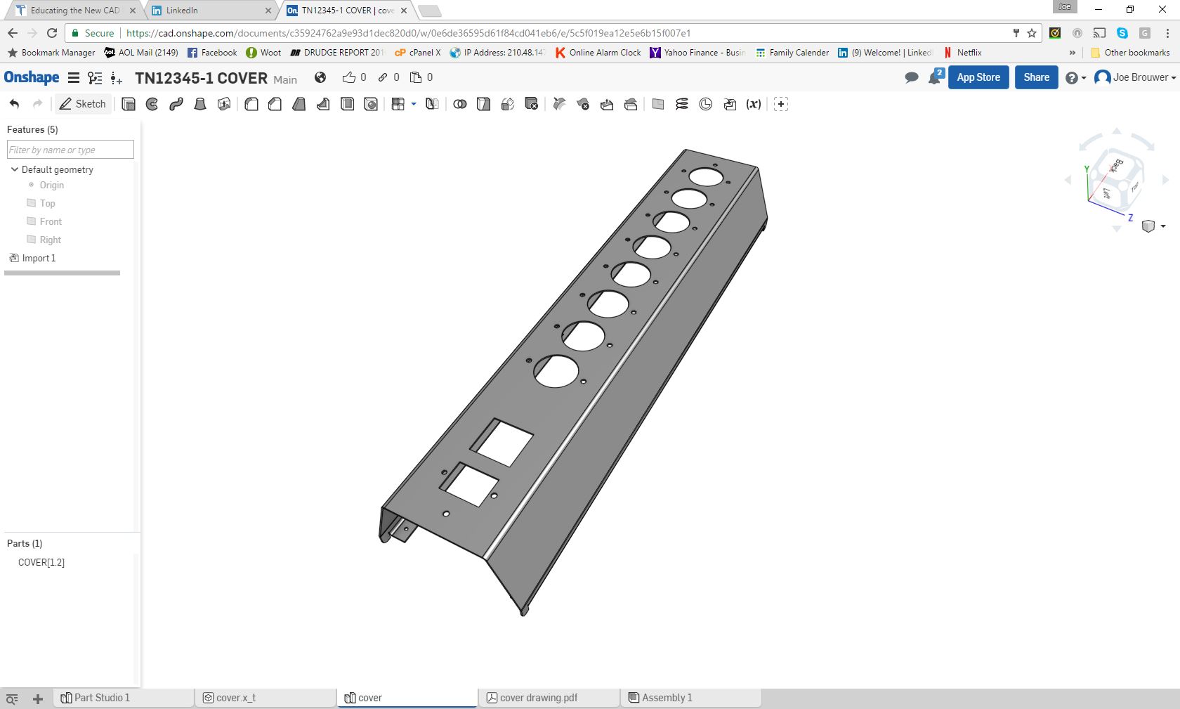
You can view the part. Yes, in 3D, rotate and review. What could be more clear? You could view the AID or even just upload the PDF of a drawing. All formats would be available. No limitations of documentation. You could set standards in the the environment.
This is actual information in Onshape!
You could just as easy have inseparable assemblies, weldments, bonded assemblies, riveted assemblies, sheet metal assemblies with fasteners, etc.
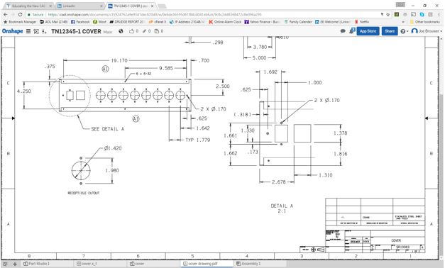
And the drawing uploaded as a pdf "IN THE SAME DOCUMENT". You can upload any file format and view it. No special software.
You could include any level of information. Today we do not draw the drawings. The drawing standards are leftover from the past. We could easily devise much more clear, concise and unambiguous documents. Especially on the assembly level. Planning and other departments could also use this system for planning orders, instruction, etc. Manufacturing could include tool paths, more instructions. Remember you do not have to have the 3D model. It will work with "any document". Amazing!! Think it through! Actually, you could offer its use to any department in the company. Easily accessible engineering information in the cloud without any special setup of the cost of the expensive Infotech folks.
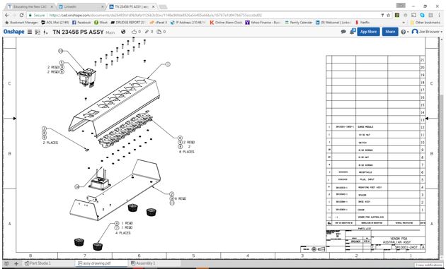
If you need the assembly in 3D, you really need to get the original file in the native system. Now if you wanted to have the complete assembly on line, it is no problem, just upload it.
Here is the assembly PDF uploaded to Onshape. No, we do not include the 3D model. Why in the world would you do that??
I suggest you create an AID (drawing). You can include any level of detail. Yes, yes, you could use PMI. At this time OnShape does not support PMI. With any demand I am sure they could make it available. But a completely detailed AID (drawing) is a much better deliverable than the obscure PMI. GD&T can be much more clearly defined (Minimized GD&T seems to be bastardized for PMI). It also gives the designer a second look for errors and maybe a new design. It is a much better format to review, check and use for manufacturing.
PMI vs AID (Associated Information Document
I can tell you from 50 years of experience in the industry as a draftsman:
"If it is difficult to detail it will be equally difficult to manufacture."
For the life of me, I cannot understand how this simple fact has been completely overlooked.
You could even scan manual board drawings as PDFs and upload them. Here is an interesting article about bringing back the 757. I wonder if today's Boeing engineers can even read the board drawings. It would be a great place to start the new 3D CAD engineer, turning drawings into 3D models. Imagine what they would learn?
I was just offered a job to convert a few old Boeing drawings to 3D models. Funny how fast they throw out the "3D model is the authority" when things have to be expedited. It shows that Boeing engineering based on Dassault Catia 5 PLM has so many holes.
Example of the state of the industry!!
I was offered another job to review a board drawing from Boeing by one of my CNC associate working for a local machine shop. He described the problem that his modeler actually found un-machinable cavities inside the part after the part was mostly done. I asked if it was a sand casting? He said no.
I got the drawing and the 3D model and sure enough right on the drawing in huge letters "SAND CASTING".
I have worked with this fellow for 20 years. I was shocked that he obviously didn't look at the drawing before calling and wasting my time. I was supposed to 3D model it. It only took about 30 minutes to review the drawing and the model in IronCAD. Sadly, the model was not correct and the error stood out like a sore thumb.
It seemed like no one looked at the drawing. From engineering at Boeing, Boeing purchasing, the supplier and the 3D CAD modeler.
Makes you wonder about the state of Boeing today. Do they even know what a sand casting is and that it cannot be machined?
Educating the New 3D CAD Engineer - 2015
There are no limitations on the level of communication that this system could deliver. All with a computer, Apple or PC, and access to a web browser!
You cannot shortcut engineering. Do I really have to tell you why?
Sadly, all these decisions are being made by those that are not engineers and do not design and have never delivered an engineering document to any supplier.
I just saw an article ‘Use Right CAD Techniques from Concept Design through Fabrication to Launch Products on Time”. This guy has a Master’s degree in Thermal Engineering? I can’t imagine a fellow with these credentials writing this article when we used blueprints. I never saw a MSME or PHD in the drafting room, and there were very few engineers on the drafting board. Now they are telling us how to create the engineering documentation.
Again, I will restate and conclude.
The Native CAD file cannot
effectively be used
as a standard engineering deliverable.
I have written article after article on this subject and one day there will be someone with the responsibility to at least consider this concept and say.
OH, I GET IT!! Our engineering is costing us a fortune!
But I believe there are not enough people with the necessary applicable knowledge to make this happen. Plus, the vested interests of the major 3D CAD systems are heavily invested in the failed PLM, MBE and PMI system that puts a company’s dependence on the 3D CAD system to manage their complete engineering department. It is like renting and being stuck with the same drafting board forever. Sadly, those that should have been involved in the implementation of 3D CAD into the industry should have been the draftsman, whose job was to create, check, release, revise and maintain the engineering documentation.
The Death of the Draftsman or “Where has all the talent gone?”
Quoting Tools: CAD Dimensioning - Another Band-Aid for MBE!
How long can the industry be fooled? I had to write this article before I wrote this next article.
CADKEY or Catia? Boeing’s Billion-Dollar 3D CAD Mistake!
Of course, none of my articles would be complete without referencing:
The Worst to Best 3D MCAD Systems Expanded!
TECH-NET Engineering Services!
We sell and support IronCAD and ZW3D Products and
provide engineering services throughout the USA and Canada!
If you are interested in adding professional hybrid modeling
capabilities or looking for a new solution to increase your
productivity, take some time to download a fully functional 30 day
evaluation and play with these packages. Feel free to give me a call if
you have any questions or would like an on-line presentation.
For more information or to download IronCAD or ZW3D
Joe Brouwer
206-842-0360