|
Cloud Based Engineering Document Control We are so Close!!  | ||
|
Please review this article for the
basic concept.
The Embedded Title Block! A PLM Solution! That was the first time I conceived of a simple cloud based engineering document control system plus the embedded title block. Onshape was released and it completely fit the concept I described. I quickly wrote this article. Onshape is a marginal CAD system and is not viable for your engineering. The problem is the lack of a locally saved file format, thereby, locking your precious engineering documentation and Intelectual property into their CAD solution and cloud storage. Very short sighted of them. Viable Options to Replace Subscription Only CAD software But Onshape offers an incredible basis for engineering document control system. As I describe in the above article this could eliminate the complex PLM that has caused so much trouble, pain, confusion and is incredibly complex and costly. The Death of PLM I don't understand how document control fell under PLM. When it was introduced, even though CAD was available the documentation was delivered as printed documentation. The problem with the PLM guru's is that they look at information as digital. Engineering is driven by documents. It is not PDM (Product Data Management) it is Product Document Management. Can you see the different mind set? It is sad that the PLM guru did not even look at the past document control system and tried and failed to recreate the wheel. The expert in engineering documentation was the drafting group, who was obviously not consulted. Engineering Documentation - A Primer for the PLM Guru!
We first have to define engineering documentation. I have realized lately with the Elimination of the Draftsman there is now no engineering documentation training available. In the past the young engineer, not trained in drafting in college, was tossed into the drafting group for a year to learn the language of engineering documentation in the larger companies. Yes, that was the drawing pre-3D CAD.
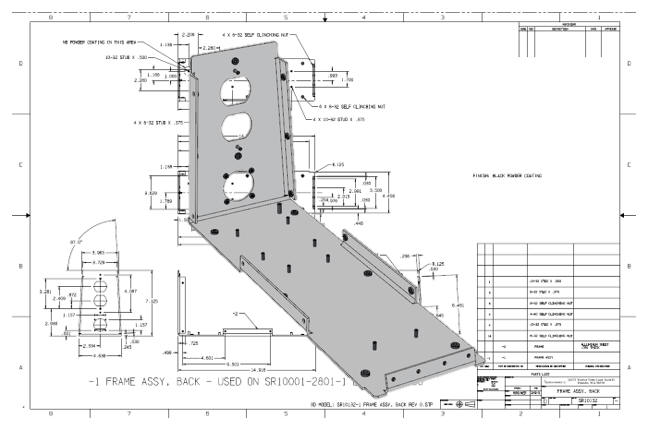
1. The Drawing - Delivered as a PDF. There are two forms of the drawing. Manually drawn or from an electronic drafting package. These documents are made up of non-associated orthographic projected views. Today, these are delivered as a PDF. Why do I reference manual drawings? Boeing is still sending manual drawings to the suppliers. It is funny in a MBE world that Boeing would overlook such a blatant violation of the model being the authority. Also there is other information that can not be based on 3D, such as different charts, floor plans, schematics, etc and can be only presented as a drawing. Note: I didn't call it the 2D drawing. This really bugs me, what other kind of drawings are there? Please stop using that idiotic term!!! 2. The 3D Model - Delivered as a native or neutral 3D file format. Today this is the replacement for the drawing. We now design in 3D, I started this in 1982 and it was in the realm of the draftsman mostly through to the end of the century due to still delivering, what Boeing draftsman fondly called the flat file, as a print. Companies soon realized that the engineer could do the design directly in 3D and there was no need for the draftsman. Sadly, they did not plan for this transition which demands a thorough knowledge of engineering documentation. 3. The AID (Associated Information Document) delivered as a PDF. In 1988 surfacing was made widely available on the PC and the model was done in surfacing providing CNC with 2 and 3 axis information this move the model beyond only used to create the flat file. Now the 3D model was being delivered to the suppliers. While the 3D model completely defines the geometry of part or assembly, it does not include information like material, finish, tolerance, process, parts list, part number, part name, revision history, used on and the list can go on. Sadly, the part number and name are only available in the file name. How nuts is that? I will again reference the Embedded Title Block! Even though solid modeling was introduced in 1988 with Pro/e it was not widely used until the release of the Parasolid and ACIS solid modeling kernels which spawned a multitude of Solid modeling systems. With this break through the 3D model became even more important. We now create the reference documentation at the end of the design cycle. The AID looks very much like the drawing. But that is where the similarities end. This is a much, much easier document to create. It is based on and associated to the 3D model and created in a documentation module of the native CAD software. Any time the model is changed the dimensions in the AID are affected and show the change. The Death of the Drawing They can be completely detailed (fully dimensioned) or minimized GD&T definitions. I prefer that they are completely detail since this gives the designer a second check on the part, an easy to review and check format and also have a well defined reference document for inspection. We archive the AID by releasing them as PDFs. They are bundled with the 3D model which make up the complete released documentation authority. The model should include a engraved or embossed title block with the information of the part. This what I call Murphy proofing the documentation. The advantage of the AID as a PDF along with the 3D model takes the documentation out of the native CAD system and in a functional Cloud Based Document Control and removes the dependency on the infotech PLM guru and the CAD vendor. 4. The PMI delivered as a native CAD file. The PMI (Product Manufacturing Information) is the basis of MBE (Model Based Enterprise) and is somewhat of a Band-Aid to solve the PDM problem of having PLM control the data management: Having one document. But that was lost long ago with these documents referencing other documents required to define and inspect the part. But we have to understand the limitations of PMI that only machined and sheet metal 3D models can be used by manufacturing. Fabrication as in weldments, bonded or riveted assemblies and other detailed assemblies when standard shapes, tubing, plate, sheet, etc or integrated components are involved you need a detail document that may or may not travel with the 3D model. From what I have seen there is virtually no support for assemblies. The following article is about a part that has nutplates referenced in the notes. I am not sure when they get installed, with an AID this would be an inseparable assembly. But we then have to look to the limitation of how Catia software handles assemblies. PMI vs AID This is an example of using a catia .catproduct assembly PMI file. It is a complete disaster. No standards what so ever, my customer could not even use it to quote the part. Actually, even though he had ZW3D that could read PMI, he had to come to me to help reviewing it. Why MBE/MBD/PMI Will FAIL Why MBE/MBD/PMI Will FAIL Part II This is a very expensive process requiring a seat of the native software or an approved viewer. These are still being sent to the suppliers as an email. It is quite shocking. I mean, what could go wrong? You have lost control of the information. Free PMI Importer? The cloud based engineering document control would completely solve this problem. Each company would set up the system to have the native PMI available in an approved format. You would have a record of when and who accessed the file. The supplier would download the native file or an approved neutral format elminating the need for a validation program if you are not using the native CAD system's CNC. They would always have access to the latest part/assembly revisions. This would be a single source for all engineering data. It could be set up for company specific information. It is truly unlimited in scope. Compare and Validation Programs? Band-Aids for Self Inflicted Wounds! Today, engineering documentation looks very much like a moving target instead of something set in stone. Cloud Based Engineering Document Control So what have I found to to make me write this new article. I have been introduced to GrabCAD's free Workbench. While it is not as robust as Onshape it would take little to make it the optimum cloud based engineering document control system. Before we jump into GC Workbench let's take a look at how Onshape handles the documentation. Onshape is a bit superior because there are no folders. Onshape is what only can be called a documentation bucket. You can load any file format such as word, excel, images, etc and it is noted on the tabs on the bottom. You can have the 3D native file and/or the part in a variety of neutral formats. The 3D model 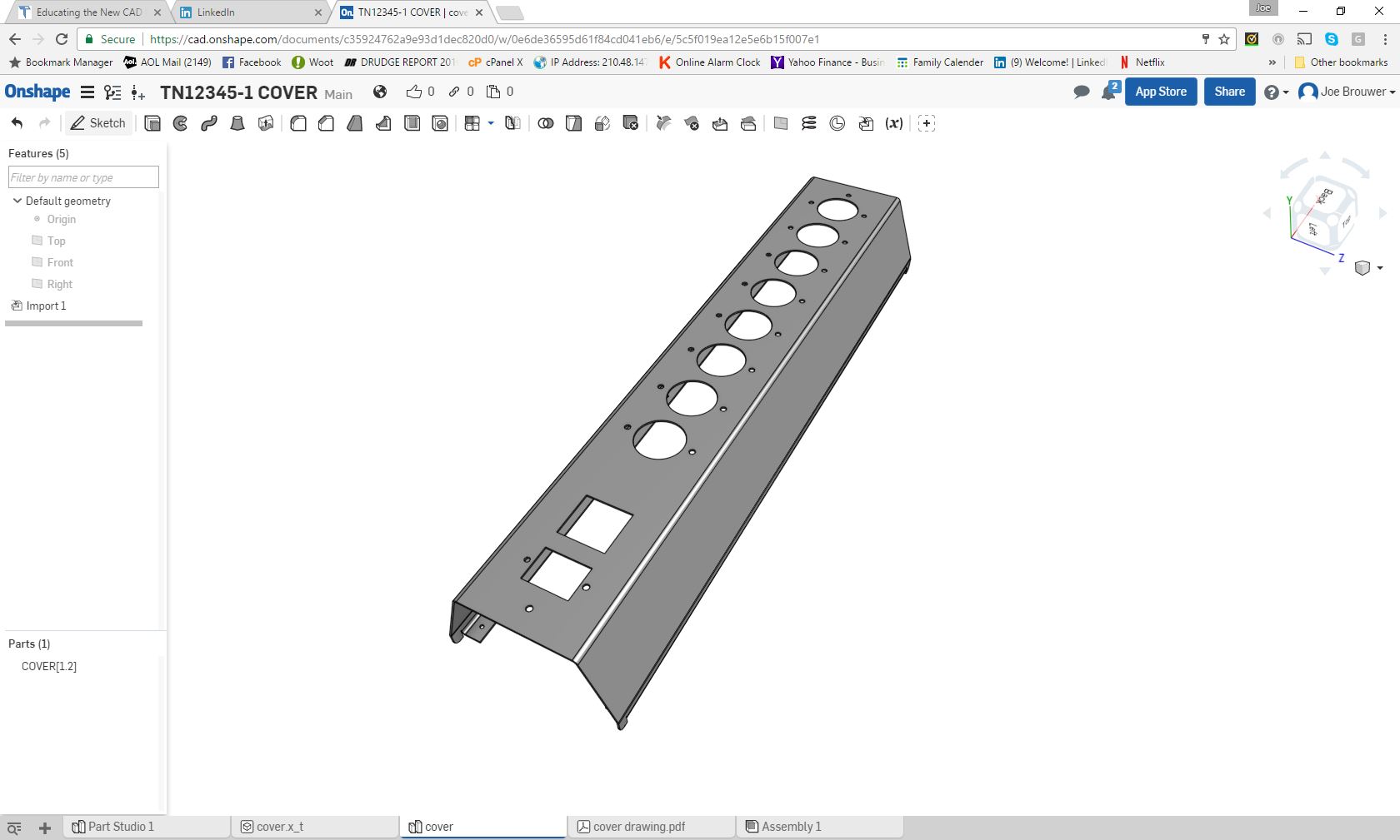 The AID as a PDF 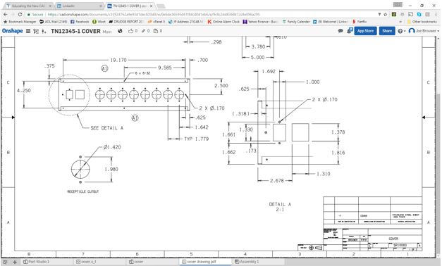 Let's now take a look at GC Workbench. Yes, I said "FREE". GrabCAD Workbench CAD collaboration tool that works the way engineers do This is a view of the PC based program. Yes it has the documentation stored locally and on the cloud completely synchronized. This is a feature that I could have only dreamed of. As for now, it really is for the smaller companies with limited sized projects. How much documentation could be managed would have to be evaluated by each company. Hey, who is that handsome guy?? 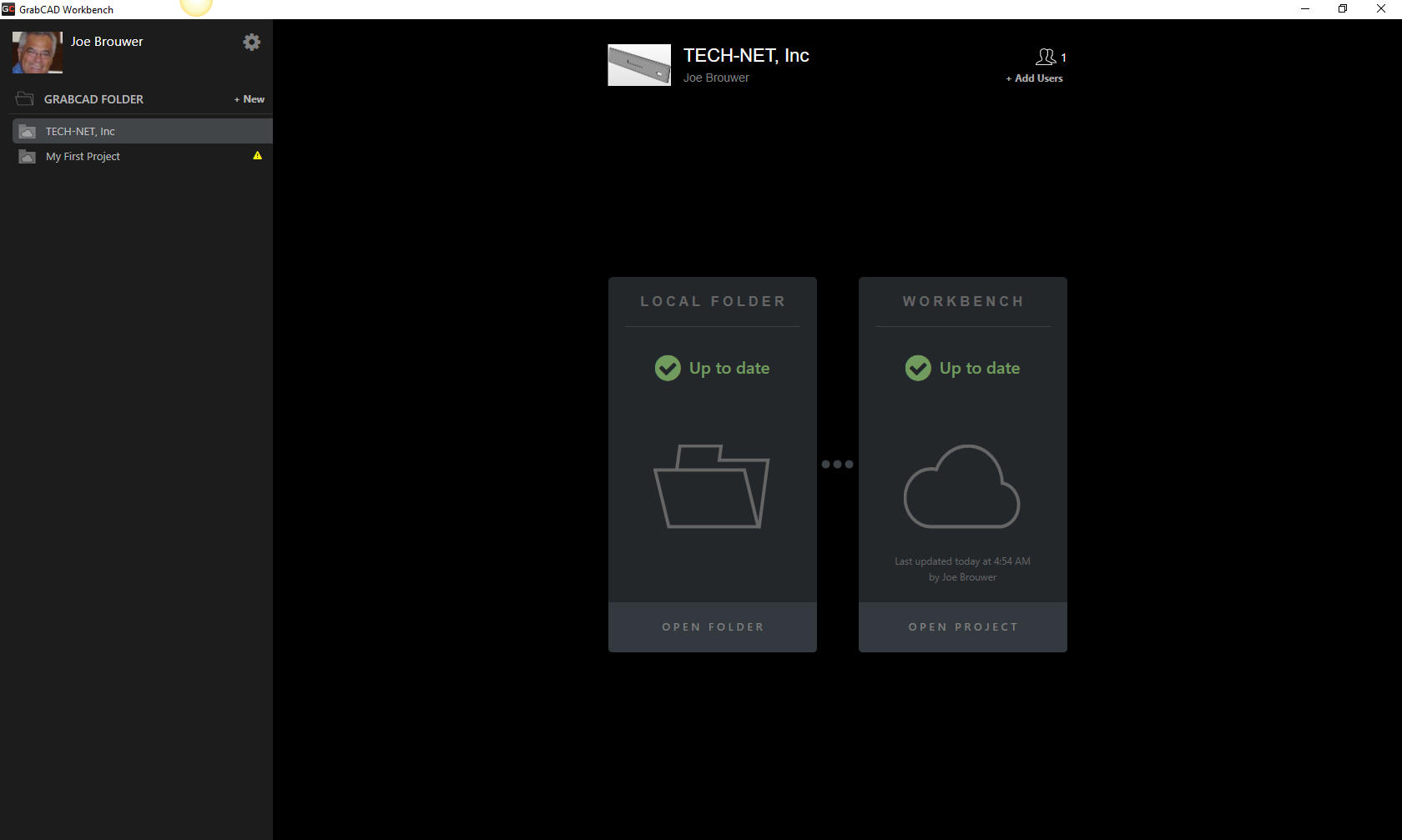 When you select Local Folder. 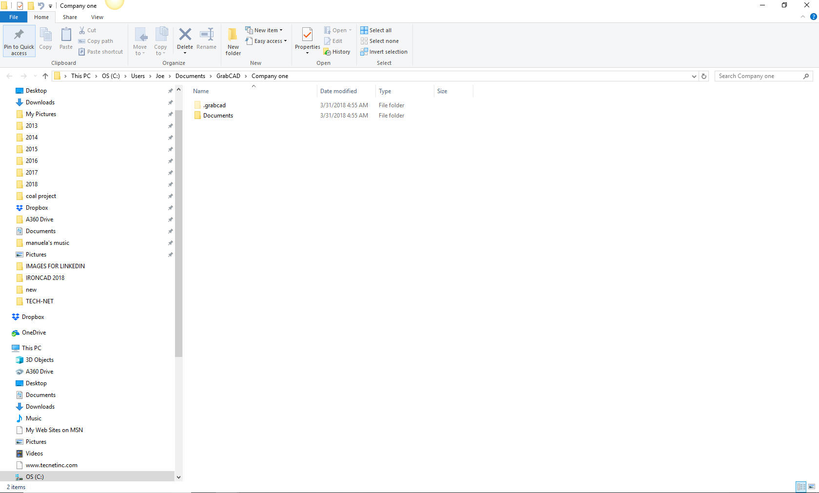 When you select Workbench 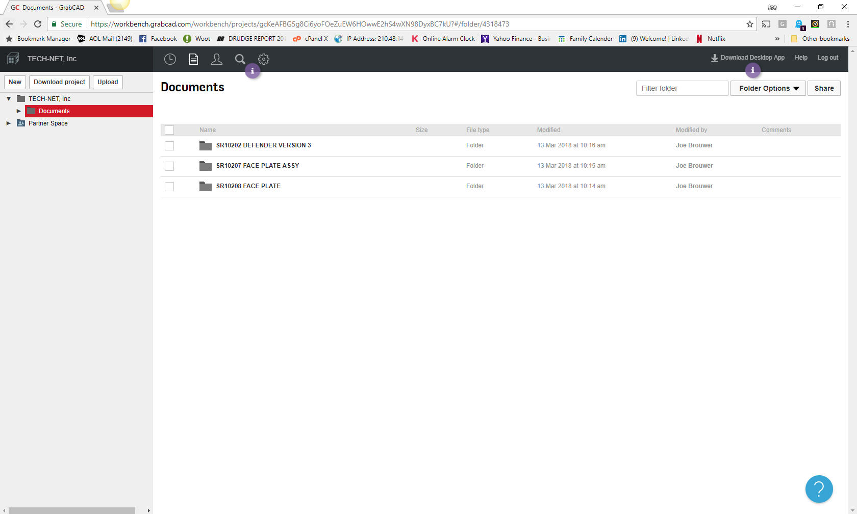 You can define those who are allowed access 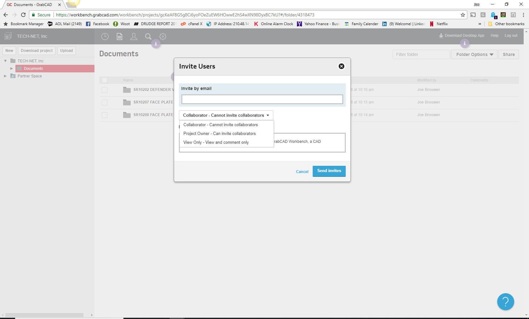 You can load a file this is a parasolid based assembly that you can rotate. 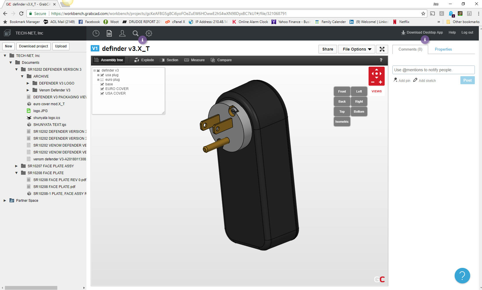 You can zoom the page 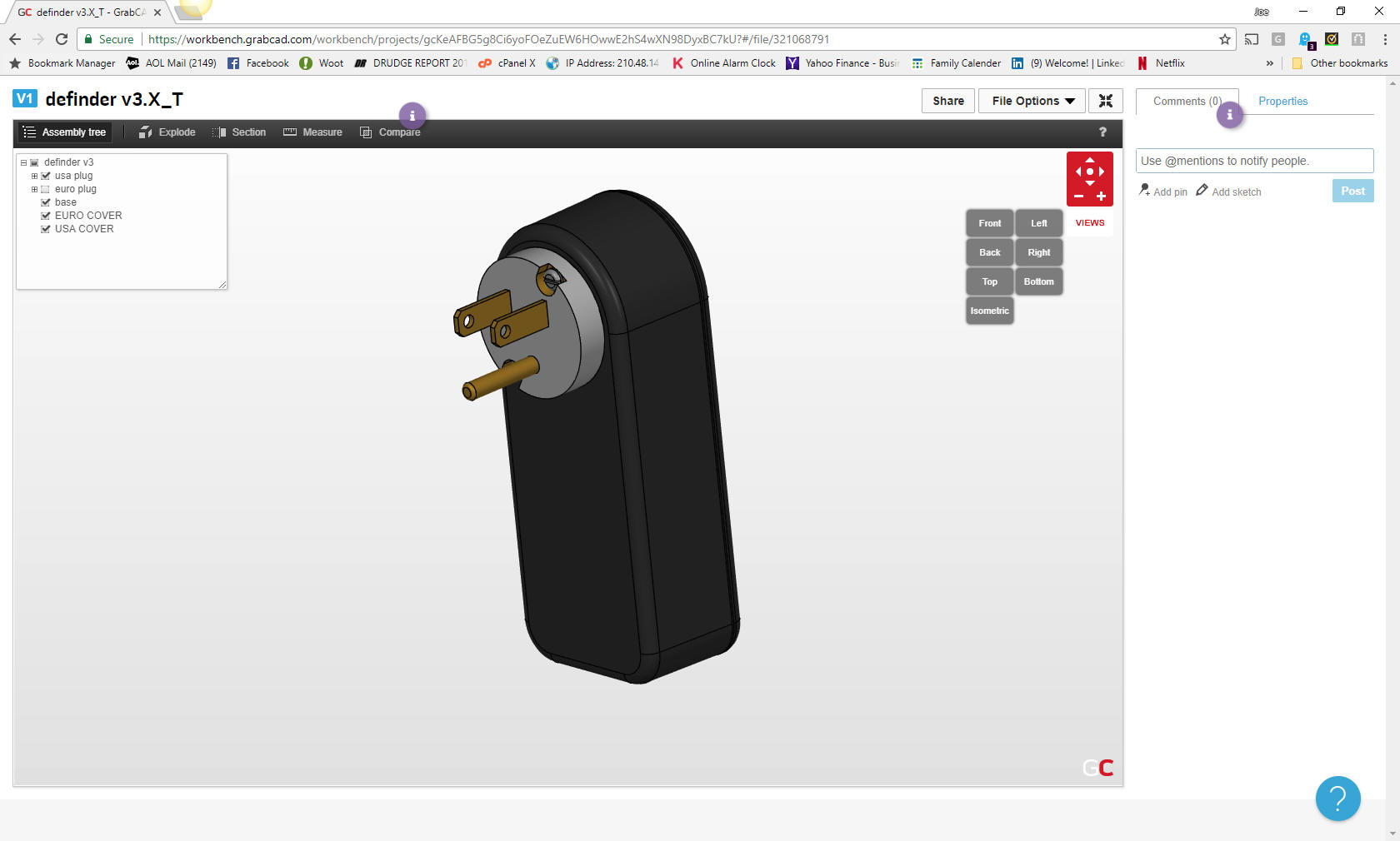 Here is the AID 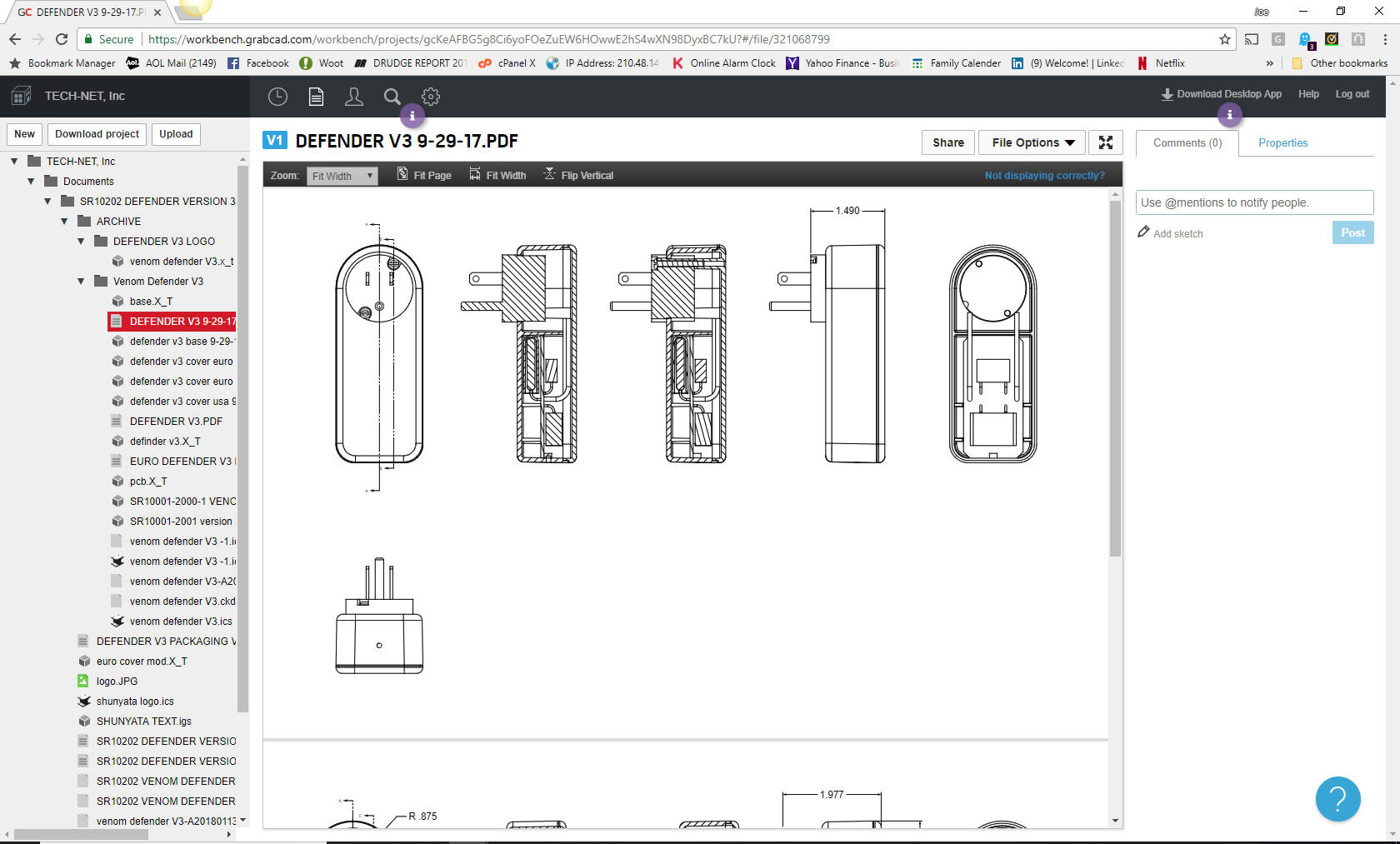 Zoomed 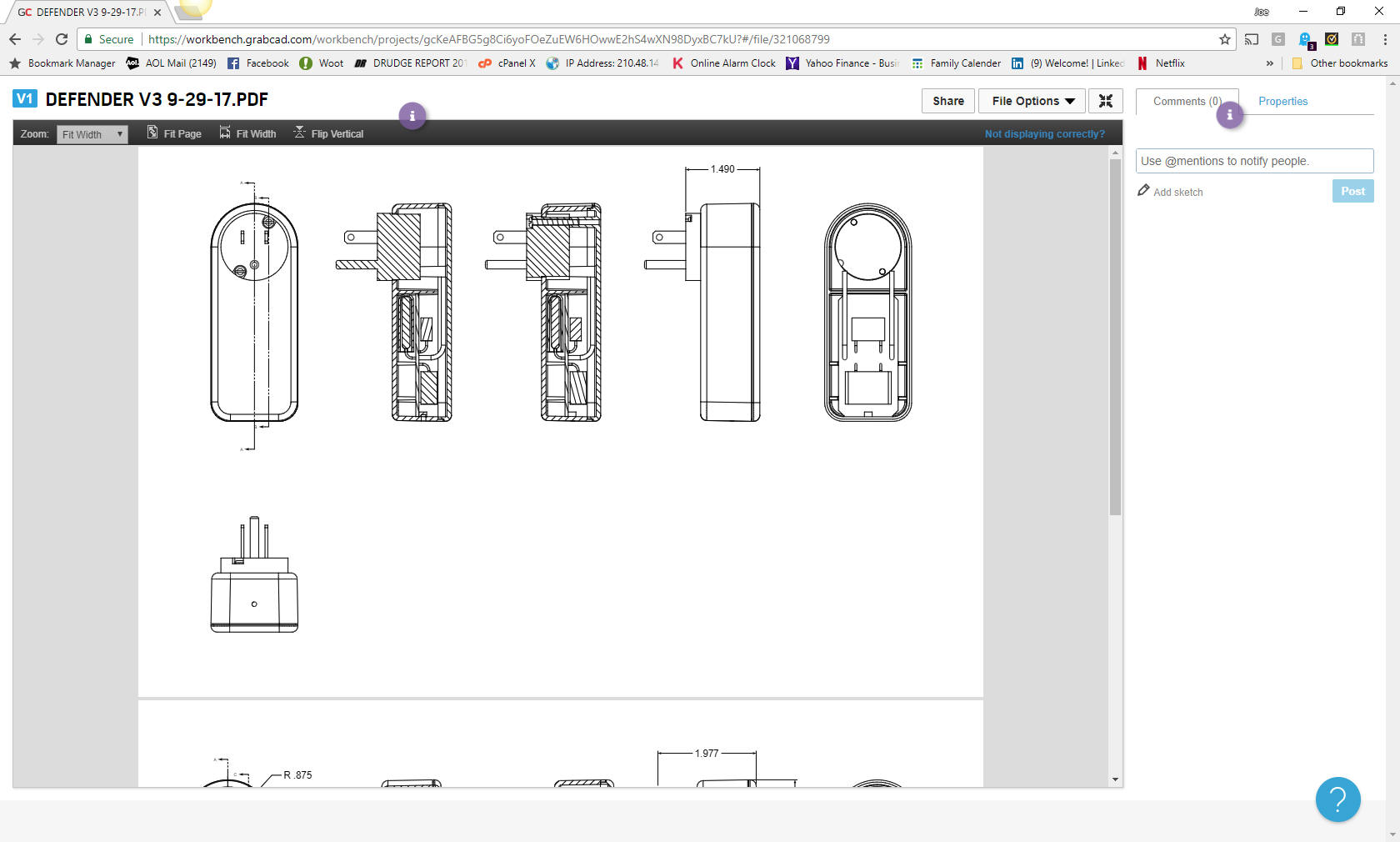 But what I envision is quite a bit simpler. All you would have would be a Google like page with a request for part number or name. 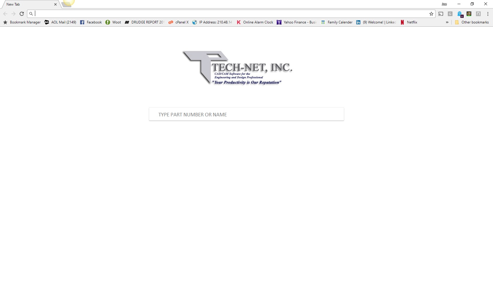 Now, of course, this would be customizable. We also have to set up a standard and release process for your documentation. If you use PMI, you can still use it, but I suggest you move to the AID/Model format. You can have both the model and drawing file included for download and modifications. Even if you are creating drawings you can keep the file and the PDF in the same webpage. There are truly no limitations on type of file format of the documentation to this concept. The cloud is nothing but a remote server so backup is the same as any documentations. You have to be a bit careful on what level of documentation you include. Most parts and inseparable assemblies are fine. We have to rethink associated parts and start thinking about complete standalone sub-assemblies. When a project is complete, we really do not want associated parts. So this has to be revised, I would look to how they were handled in the days of the drawing. All part files would be available in the webpage. I use a single model environment, I suggest you look into this concept, it eliminate much of the document management and offers a much more productive design environment. Both IronCAD and ZW3D have this functionality. You can see its increased productivity as compared to Catia 5. IRONCAD vs Catia Lesson 3 Assembly ZW3D vs Catia Lesson 3 AssemblyBut understand the cloud based engineering document controls system is not just for suppliers. This would be very similar to the blue print counters or microfiche machines of the past. It would be available to anyone with a need to view the documentation. Purchasing, marketing, sales, tech pubs, manufacturing, planning, tooling, analysis, materials and even the design engineer would look here first for the latest release. He/she would they have the information to scrutinize and establish a plan before checking the original documentation (documentation includes the 3D model) for modification or to be used in a new design. The design engineer could check out the part for any revisions. Depending on the change you could limit access to the web page with a notice that this part is being reworked. Imagine, instant notification of any changes, putting a stop to any manufacturing in progress. All revisions are included in the web file, again, having one current source for all engineering documentation. There you go, a functional standard cloud based document control system completely Murphy Proof. Well, as close to Murphy Proof we can get, we are only human after all. Cost? Virtually nothing, it would be managed by a small inexpensive admin staff outside of engineering, leaving the design engineers free to do their job of design and documentation. Also you can have multiple CAD systems with little complications, since the released engineering documentation is outside the native CAD system. You will have a reference in the documentation of the system type and file name. Just think, you are not at the mercy of a specific high-end costly CAD system. So how do we get there? The first product that offers this flexibility could actually set the standard. I hope GrabCAD or Onshape realize what they have and develop: The Ultimate Cloud Based Document Control System! TECH-NET Engineering Services!
We sell and support IronCAD and ZW3D Products and If you are interested in adding professional hybrid modeling capabilities or looking for a new solution to increase your productivity, take some time to download a fully functional 30 day evaluation and play with these packages. Feel free to give me a call if you have any questions or would like an on-line presentation. 206-842-0360 |
TECH-NET ASSOCIATES | RENDERING OF THE MONTH | CAD•CAM SERVICES
HARDWARE | TECH TIPS | EMPLOYMENT | CONTACT