|
PMI (Product Manufacturing Information) vs AID (Associated Information Document) | ||||
PMI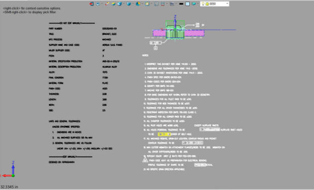 AID 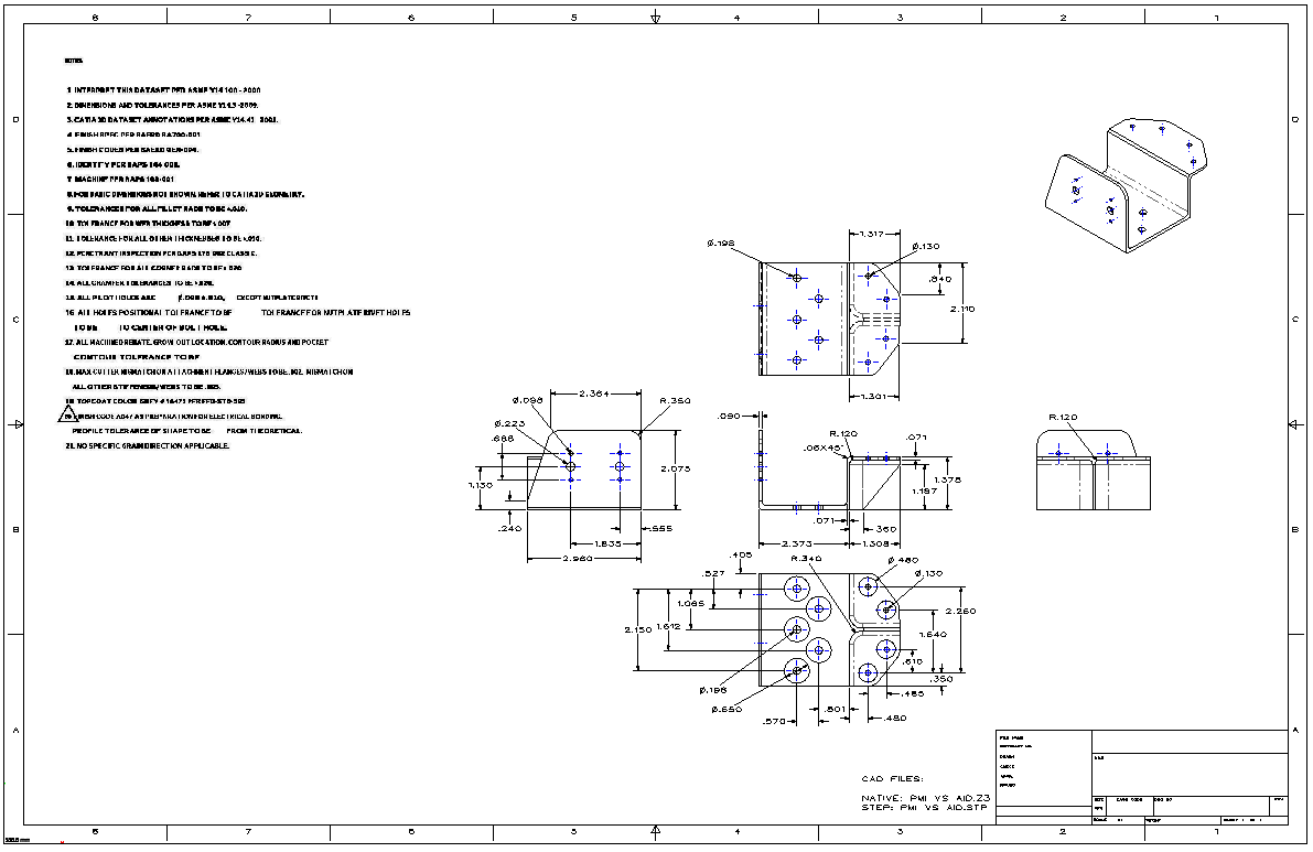 To start I will give a few definitions. MBE - Model Based Enterprise This seems to be the overall title for this unworkable convoluted mess. MBE is mostly only used by the largest of companies that can afford this failed experiment. It seems mostly prevalent in the airplane companies. The way Boeing goes, so goes the industry. I can hear Dassault patter now, "Boeing uses it so it has to be good"! I have worked with Boeing and Catia for over 30 years. Dassault is responsible for keeping Boeing one of the most ignorant and isolated manufacturing companies. Their lack of interoperability is beyond belief. MBD - Model Based Definition MBD and MBE seem to have a bit of confusion of what each other mean. I assume MBD refers to the actual modeling PMI - Product Manufacturing Information This is by far the silliest engineering deliverable ever devised. Here are two articles from PTC and Solidworks that show a complete lack of understanding of engineering documentation. It is like no one there has any experience and have never released any documentation to manufacturing. Solidworks Totally Misunderstands MBD PTC's Creo Totally Misunderstands MBD Why do we have this convoluted process? PLM working with the current popular CAD programs based on Pro/e's (Creo) paradigm of separate part, assembly and AID (Associated Information Document) found it very difficult to keep the part and AID synchronized. So they thought if it was one file it would be easier to manage. These folks did not have any knowledge of engineering documentation and thought that the native CAD file could be used for the engineering deliverable. I will show you why that will not work. One important note, the above process was developed when the engineering deliverable was the "paper" print along with the 3D model. Adobe Acrobat and the PDF was just around the corner and may have altered the direction of engineering documentation, by getting it out of the CAD system.
The Engineering deliverable is the documentation that goes to manufacturing. Engineering usually does not know the final supplier. They just have to make sure that the engineering documentation is concise, complete and unambiguous.
The PMI is in the native file format of the companies CAD system. Now, if it is to be used as the engineering deliverable, it has to be widely available to any department in the company and any outside supplier. It also should be as equally available as the blueprints of the past. But these are not easily available, in fact they are quite out of reach. We have to have the native CAD system or a compatible viewer. Now this has to be made available with a PLM document control system. I have come to the conclusion that PDM (Product Data Management) should only work inside the native CAD system and only available with access and knowledge of the CAD system. This would be similar in operation as the drawing vault in the past. Of course, I may be wrong, which even makes this more confusing. The PMI data is in 3D space. Not easy to work with. It doesn't have dimensions, just some feature qualifications controlled by quite obscure minimized GD&T. You have to have a native CAD system or CAD system that can import this information. At this time there is no free standard translator. The STEP Translation Fraud There is an effort to create a STEP PMI standard. Unless you are going to create STEP files and use them as your engineering deliverable this is basically a waste of time. For anyone that wants to access the information in a STEP format they would have to have someone convert the part or assembly to a STEP. We really don't want to send out native files (you can see why below). We want to send it out in a format where the PMI information is not part of the model. We just need to easily view it and it must included the native model. All documentation should be in stone, where any alteration cannot occur. MBE PMI Validation and Conformance Testing Project When you make the model the authority it has to be the "Native" model. Boeing and other large companies that are using MBE require the suppliers, if they do not have a seat of Catia 5, to purchase validation software to assure that the model being machined duplicates the "native" Catia 5 model. Apples to Apples? Of course, but Catia 5 produces some of the more corrupt files. Compare and Validation Programs? Band-Aids for Self Inflicted Wounds! Corrupt 3D CAD Parts 3rd Party Translators There are 3rd party programs that will read the native PMI files, but they have to keep up to date with the different versions of the 5 popular CAD systems. So these can not be the standard. Also they do not meet the original "native" model requirements. Many suppliers are using the files without the validation process. Many first tier suppliers use second and ever third tier suppliers. Many use independent CNC programmers. One associate called and ask it I could read PMI. This was before ZW3D could read PMI and he ended up buying one of the popular translators, of course, violating Boeing's rules. Remember any translator is only a snapshot in time, only good until the next CAD version is released. There you go, the PMI in a native CAD files causes too many problems for it to be a standard. Now, I am sure many are happy not to have a standard. But not having a standard is costing the industry a fortune. Now the smaller companies have not implemented PLM, MBE, MDB and the PMI. It is just not cost effective. Large companies obviously have millions maybe billions to waste on this overly complex unworkable system. What do the small companies use? They create a fully defined AID (Associated Information Document). This of course looks just like a drawing and has all of the dimensions and annotation on a sheet, but it is based on the 3D model. It is printed as a PDF and is stored with the native or neutral format of the model in a folder. The AID is treated just like a drawing and has all of the information on one or many sheets in one PDF. It shows the revision history. It can be printed and easily used for design review and checking. Like the name describes the AID is directly associated to the model. Any changes to the model are automatically reflected in the AID. Is there anything special needed to view this information? You just need an adobe viewer to view the AID and a compatible CAD system to access the model. Virtually no cost. That is why I say that the MBE system will fail. Why MBE/MBD/PMI Will FAIL Why MBE/MBD/PMI Will FAIL Part II With all of that under your belt let take a look.
We will start with the Catia 5 PMI. This is a sample part from a major aircraft company. I will import the part with PMI data into ZW3D. This will probably be the first time many of you have see a production PMI. Mostly, we see simple parts without any annotation. We have brought in all of the graphics. I am not sure how many other viewers work, but realize this is a 3rd party importer. Have any of you worked with dxf? You know you do not always get the perfect results. This is another problem with the engineering deliverable based on a native file. You cannot view the notes in one screen. How do you print them to use it? Snipping tool images? That is what I am showing you. Can you imagine the pain this causes planners, estimators, quoters, machinists, inspectors, etc. How about checkers? How do they review the documentation. You can see this process is not thought through. 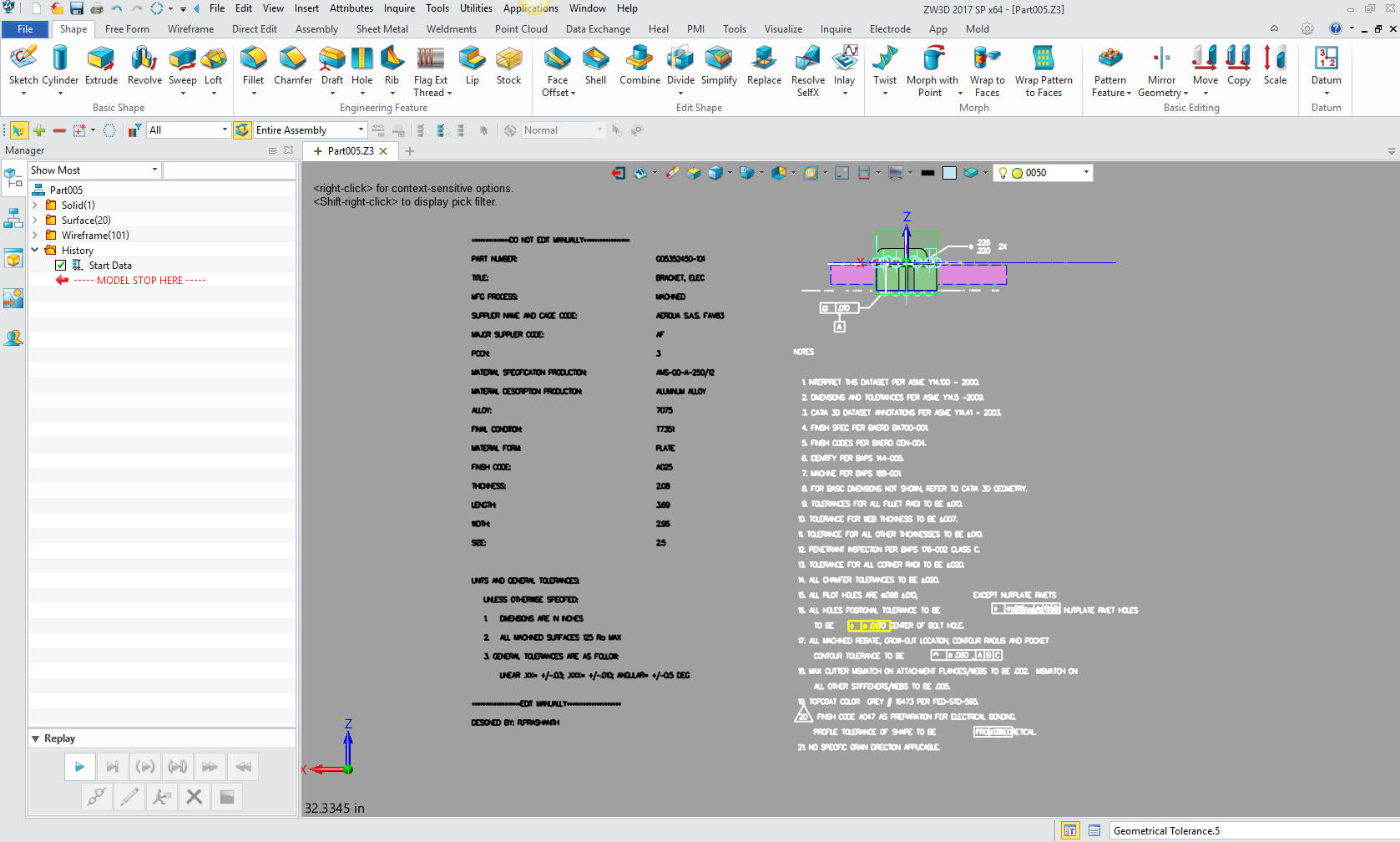 Let's take a closer look at the part itself we will get into the annotation later. They have some of the construction geometry we have to turn off. No extraneous information should be sent to the supplier. You need to have a clean net model unless there is some geometry needed for manufacturing that would be covered in a note. I would suppose that is a good reason to send the model as a neutral file such as a STEP. You could see many PDM problems with a "model only" native file. I am not sure you can save the native file with any of these entities turned off. 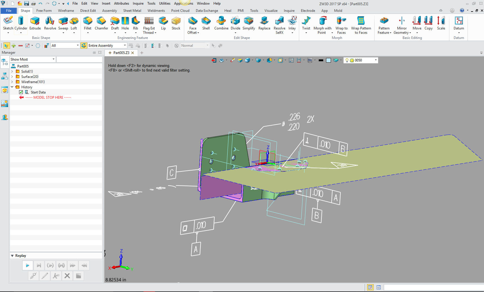 There are a couple of 3rd party programs that do a couple of things. Some actually put the PMI on a sheet. But as you see with the extensive notes, how could they be put on a sheet automatically? The PMI system is so useless by itself for quoting, that a software company has released another 3rd party program to just create quotes. It actually provides the ability to create 3D dimensions to find out the size of the part. Quoting Tools: CAD Dimensioning - Another Band-Aid for MBE! ZW3D reads the native file and it is now a ZW3D file. And as you can see below is one of the few systems that the AID is integrated into the one file. Free PMI Importer? Ah.. this looks better. So what are we looking at. Is a relatively simple model with at bit of feature control. But you have to have it available on your computer to review it. Also, virtually all of the tolerances are provided in notes. I am not kidding. I can only come to the conclusion that those that have devised this system have not followed through on the implementation. Any draftsman worth his salt, would laugh at this and question the sanity of those that are responsible. Does anyone besides me think that +/- .003 is a bit tight for a nutplane clearance hole? 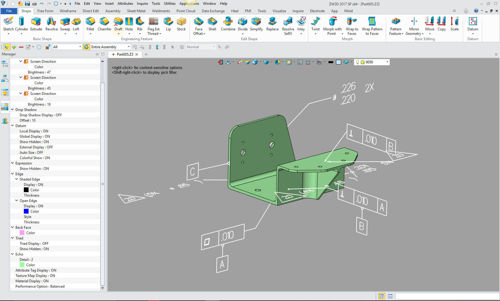 Now if I had to show you all of the GD&T info I would have to show you 3 views. But many parts have many different planes where more definition needs to be displayed making it even more cluttered and confusing. Let's take a look at the other annotation. We cannot view it all at once. This would be a problem with any system. First thing that bothers me is it says "DO NOT EDIT MANUALLY". Hmm This is obviously read by another file. Oh, oh, another file to maintain. You would think it would be made read only. 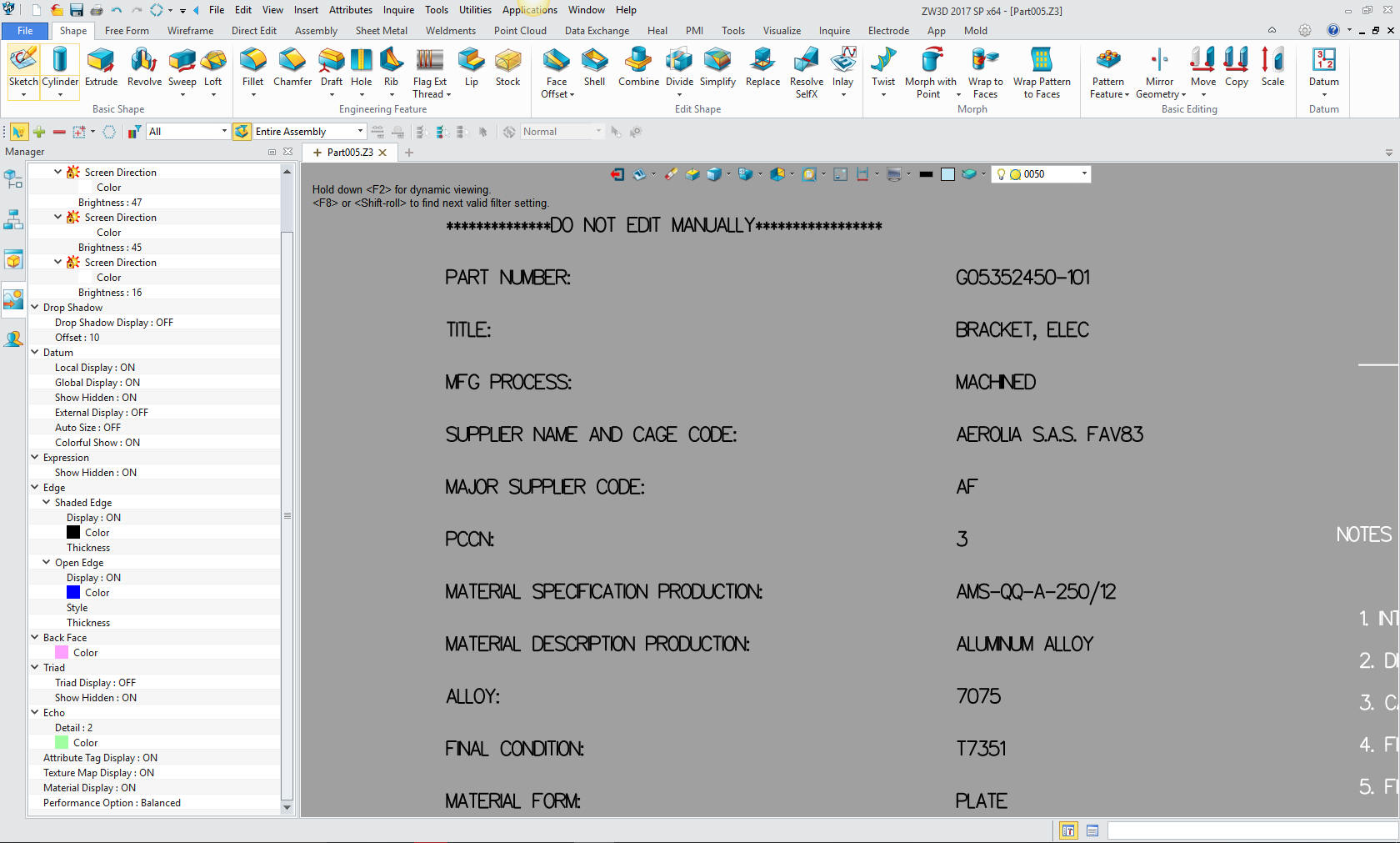 This is interesting. Dimensional tolerances. This is pretty much Boeing UOS standard tolerances. But dimensions on a PMI is a bit of a no no. But here they are. 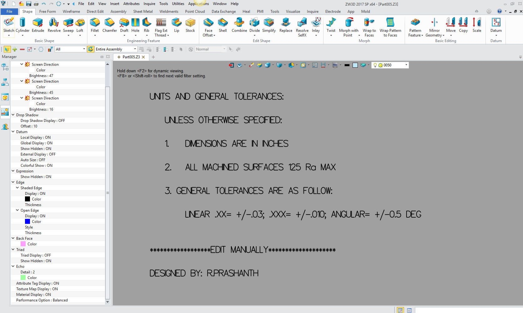 Now this is quite bizarre. They have tolerances for all of the features and even sizes for the holes defined in the notes. Now, even the most ardent MBE person has to shake his/her head. Is this is ludicrous? No, it is an attempt to make this system work. Since there are no standards, it is up to each company to create them. It is funny how they assume the suppler knows these are nutplate holes. Actually when do the nutplates get installed? This would be a detailed assembly in the past since it is inseparable. Another level of ignorance by those that do not know engineering documentation. It even makes reference to nutplate rivets. If this is a sample for the suppliers (from which I got it), it surely is not a good one. You would expect it to be thought through and represent the best of their documentation. I expect this level of incompetence runs throughout their PMI documentation system. It would make you yearn for the days of the drawing. Of course, if any of you were around then.. LOL I actually think when we based the engineering on the "drawing only" it was more cost effective. All we did was add the 3D model as a pattern. You would think it would be more productive. Well, keep on reading, I show the way! You can see we did not get a perfect translation. Or maybe we did, who knows? 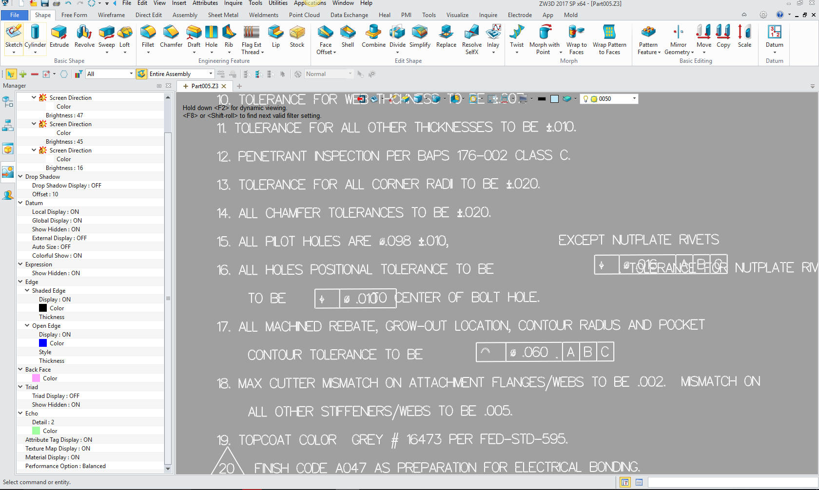 So there you go. Viable engineering deliverable? Absolutely not! The Solution - Back to the Future CGED - Computer Generated Engineering Document This was the very first format used with 3D CAD. Computervision (1982), Catia (1985) and Pro/e (1988) were developed to making the drafting easier. But the product was not a drawing, there was no drawing done. They were dimensioned instances of different views of the model. The Death of the Drawing Since it served the purpose as a drawing and was released as prints they continued to call them drawings. Today, many call them 2D drawings. How redundant is that? What other kind of drawings are there? I coined these CGED, the Boeing draftsmen were a smart bunch and called them the "flat files" as compared to the 3D model. Soon surfacing and solid models appeared and the model could be used as a pattern for manufacturing. Enter the AID - Associated Information Document The AID and 3D model are the engineering deliverable. While the AID, can be a standalone documented, it is designed to accompany the 3D Model. Lets make the AID! First we blank all of the annotation. 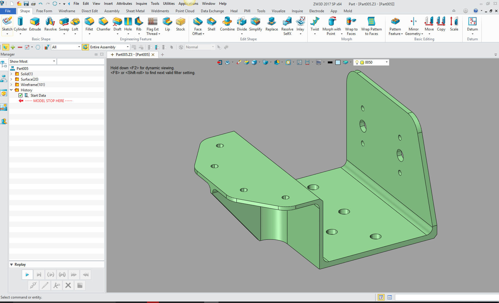 We can do this in ZW3D in an integrated AID. Now we create a 2D sheet (Yes, I know, what other kind of sheets are there?) What I have done is just detailed the part. The notes and tolerance can be applied to the dimensions. But this is the basic difference in time. Is it worth the lack of information? Now there are many things that don't need to be noted and we have the model to compare. I have detailed this without any GD&T. GD&T is really not required. You can still equally inspect the parts. Notice that the dimensions come off the same face or from a feature. These were implied datum's. This is how we defined how the part must be inspected. The drawing is an inspection document, we didn't care how the part was made as long as it matched the drawing. In the past I would make sure my dimension were incredibly thought through showing the correct relationships, only to see the tooling drawings with all the dimensions defined with base dimensions. Those were in the days when they actually turned knobs to machine the parts. It drove me crazy. Today, of course, they are CNC programmers creating tool paths directly from the model. Today inspection has the model with the AID. This part would be mostly covered by the UOS note. You can see the UOS in one of the above images. Now, before all of you GD&T gurus start jumping on me. GD&T is based on feature control and a much more precise way of tolerancing. But rarely needed in 80% of the parts. But there is a vested interest to make it the de facto way of tolerancing and keeping the PMI viable since you cannot dimension in PMI. It would be just be a cluttered mess. I consider the minimized GD&T, as presented in the PMI, a bastardization of the intent of GD&T. With an AID we would have many less notes. The text in the PMI is a graphic entity and not usable. I just created an image and inserted them as an example. This is just an example of how this works. I should have included the nutplates and made this an inseparable assembly. The above PMI would probably require another documents showing the installation of the nutplates. I still have not seen a released production PMI assembly. One of the benefits of creating the AID is that it allows the designer to check for errors or a better design. It also is a much better format for review and checking. It offers a higher level of certainty on the correctness of the part. It leaves no doubt in the minds of manufacturing. They can print it and have it in front of them for reference. And If you look at the PMI there are many reference notes that are not easy to view. I am not sure that MBE is the total culprit for the state of engineering documentation today. But here is an article that will have you rolling your eyes in disbelief. Engineering Documentation Today! The Reason I do Completely Detailed AIDs I would release my plastic parts to the mold maker without an AID, just the model. We were working with China on some molds. We shot our first parts and I noticed that a couple of the ribs were taller than the others. Now, this did not alter the functionality of the part, but it was quite sloppy. From then on I would completely detail the parts. I found it much better to have an AID to refer to for any problems than going to the model itself. It was much easier for the customer to have the AIDs to archive. Actually, as you think this through, you could not use PMI as your engineering deliverable when you have to deliver the engineering to a customer for review and archiving. These are not 3D CAD people, and don't want to be. But there is some thing interesting in this part. I noticed that this face was not perpendicular by the difference shown. 1.317 and 1.308. This is less than one degree on a face that does not appear to mate with any other part. Is this part of the design or a small error? Every time I make an AID I usually find a small error or even a better way to design and I have 52 years experience. I have to tell you this is sloppy modeling even though it is small. We all know the part has to be dead nuts! 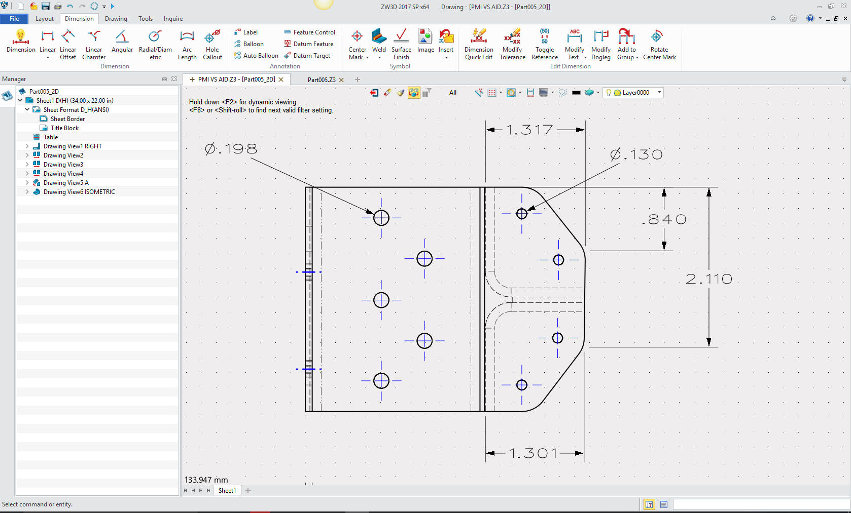 Here are areas for a special finish defined by circles. They are not centered. These are quite obscure in the PMI. This step has nothing to do with machining and is part of the finish instructions and is only defined in the notes. Planning is probably pulling their hair out and creating a well defined AID with clear and concise instructions. What do we save by catering to the PLM folks to only make it much more costly down line. You have to know what you need when you import the part. These circles are imported as wireframe. There are other extraneous entities also imported as wireframe. If this sample file represents the delivered engineering it is quite lacking and is an embarrassment. But without a standard what can we expect? This is just a simple part, can you imagine a complex released part? I can't 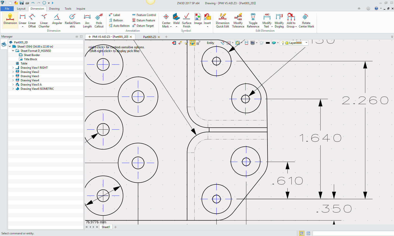 There is one very important bit of information that has to be included on the AID. We have to reference the native part and/or the STEP file (or what ever neutral file agreed upon) on which the AID is based. 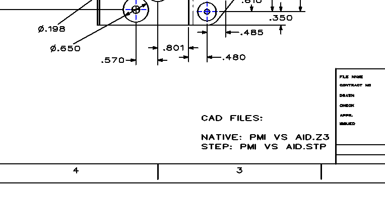 As you can see the AID is very simple and easy to create. It offers so much more to engineering than the PMI. But we need to realize the AID as a PDF gets released along with the model. It is outside the CAD system and requires no special software to use or view it. I can send any of you industrial/mechanical design professionals the model and AID and you could totally understand it. The same goes for the manufacturing professionals. You don't need a myriad of viewers or STEP and 3rd party translators, just access to these two files. Even the engineers would look here first then move to the CAD system to make the changes. The native CAD AID is there for easy modification and revision history. Imagine changing the PMI and noting the changes? Do we really need huge studies on how to communicate our engineering information. It is quite a joke that after a decade that this standard has been in place they are still trying to figure how to communicate it. We need a separate "Document Control" group. This would put the engineer back in the job of engineering. How many BSME's, MSME's and PHD's have made of career of data management? Wasted degrees? You tell me. The major CAD system have made PLM the basis of their programs. Can you imagine the 3D CAD system used only for design? How easy would that be? Basically, you could use a system more conducive to design with a decent AID module. (See the Integrate AID, below)
So our engineers are trying to use this silly complex system to deliver our engineering documentation. Here is a comment by a highly experienced engineer that is actually using PMI for the deliverable. "The big problem is, any failure will be blamed on the responsible engineers and not an unworkable system. MBE is already being backstopped by drawings in many organizations that are forced to use MBE, but the drawings are frequently not in the release control process because they are not the "primary" data driving fabrication. A fine mess.." So tell me which is more cost effective? Another Solution: The Integrated AID Let's take a look at the Integrated AID. When I was working at Boeing and was introduced to CADKEY, they developed the integrated AID or the "Layout Mode" as compared to the "Model Mode". CADKEY had a single model environment that allowed you to do multiple parts in one space or file. You can do complete projects in one file. You could also create all of your AIDs in the same file. If Boeing would have based its engineering on this concept instead of Catia 5 and its separate AID, I would not hesitate to say, we would not have PLM or MBE or the idiotic PMI today. They would also have been on the PC a decade earlier. Dassault has been fooling Boeing upper management for years. CADKEY or Catia? Boeing’s Billion-Dollar 3D CAD Mistake! Recommendations to the New CEO of Boeing ZW3D also has that the integrated AID, as you can see. This is so incredible cost effective it is worth the move. Imagine, no synchronization of the model and the AID. Just a click with the right mouse button and you have the AID available to revise in both the part and assembly, The lack of this functionality in all of the major CAD programs have cost the industry millions, if not billions, in trying to work around the separate AID problem. But again even with the Pro/e clone we can move the engineering documentation out of the native CAD system and into a easily managed document control system. In conclusion: This PMI sample shows a level of sloppiness that is intolerable. It lacks an incredible amount of scrutiny. It defines the information in a format that is nearly impossible to use. It shows that the engineering department does not know the requirements of those that would need this information. In the past the drawings had many eyes review them. Outside the realm of the different engineering disciplines review of the design, the basic standard format, completeness and correctness had the draftsman, checker and lead engineer review it before release. It is time for engineering to get back in charge of engineering. We need the expertise of the old draftsman to bring their knowledge back into the process. We need to actually create cost effective and useable engineering documentation. At least equal to the blueprint of the past. The Death of the Draftsman or “Where has all the talent gone?” Our problem is that the fox is in charge of the hen house, in the form of the major CAD vendor, PLM guru, MBE proponent and others with vested interests. This leaves most of the engineering managers in the dark, blindly trusting these sources. Engineering Documentation - A Primer for the PLM Guru! But one day there will be one bean counter that stands up and says "This crap is costing us a fortune". And some CEO will give the VP of engineering the task of studying it. He/she would have to be very clever and not look to the industry hacks. Most of those hacks don't have "any" applicable engineering industry experience. Hopefully, he steps out of the box, he brings on an old experienced draftsman that can show him how we did it in the past. He talks to manufacturing and ask their opinion and what format they would like the documentation. I was there when Boeing started dictating that the supplier use the unworkable MBE. They rolled it out without any notice. No, introduction at all. It all was quite bizarre and incredibly confusing and still is. Can Engineering Survive without the Drafting Group? They would have to start with the basic building block of engineering: The Individual Part Design and build from there! Not PLM, data management, MBSE, MBE, MBD and other extraneous failed experiments. So there you go! Will anything happen? We will see.
|
TECH-NET Engineering Services! If you are interested in adding professional hybrid modeling capabilities or looking for a new solution to increase your productivity, give me a call and I will send you a link to download a fully functional 30 day evaluation and a starters guide. Play with these packages awhile, then give me a call if you have any questions or would like an on-line presentation. For more information or to download ZW3D or IronCAD ZW3D Learning Mechanical CAD The Ultimate CAD Program Ironcad Five Functions that Increase CAD Productivity!! IronCAD vs Solidworks and other Pro/e Clones Joe Brouwer 206-842-0360 |
TECH-NET ASSOCIATES | RENDERING OF THE MONTH | CAD•CAM SERVICES
HARDWARE | TECH TIPS | EMPLOYMENT | CONTACT