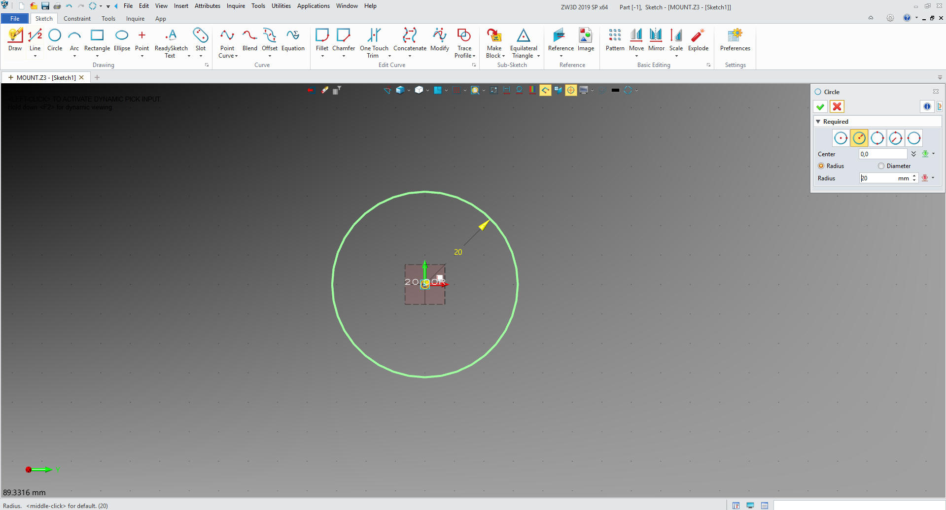
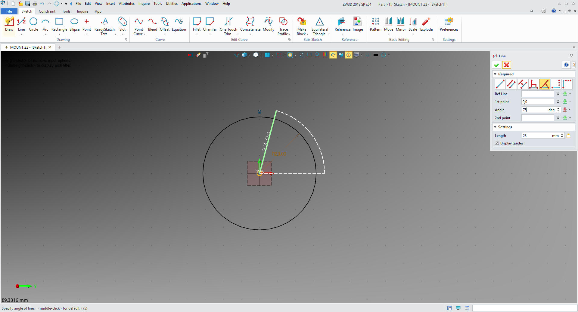
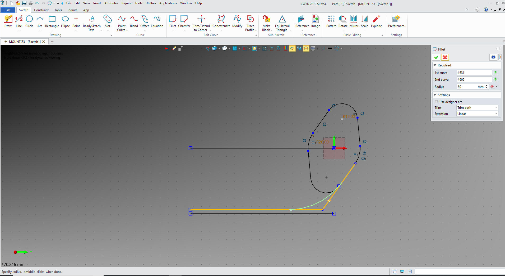
We extend the diagonal line to the mating line.
We are going to put in a 50mm radii
since it is not a mating face and will not matter.
I have seen three other Solidworks
clone users define a radius using tangent to an arc, it results in a
arc that goes out 3 places and looks like the designer didn't think
it through, LOL. Tangents do not exist in the real world, once this
is done there is no way to inspect it.
Sadly with CNC and non-contact inspection
standard drafting standards have been thrown out the window. We now
have a bunch of CAD jockeys that have no idea of what parts should
be based. All the draftsman are gone so we are entering a new
world.
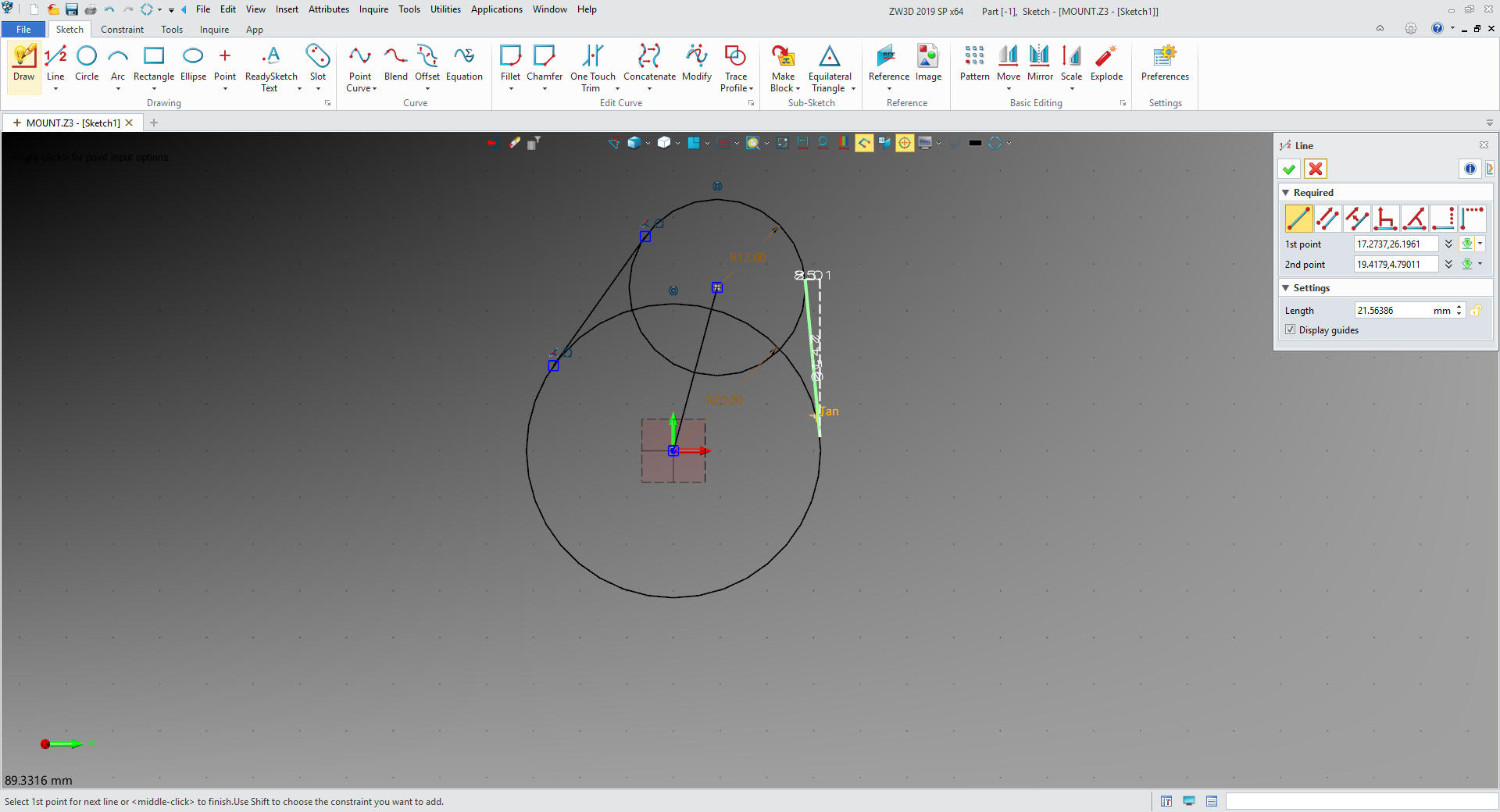
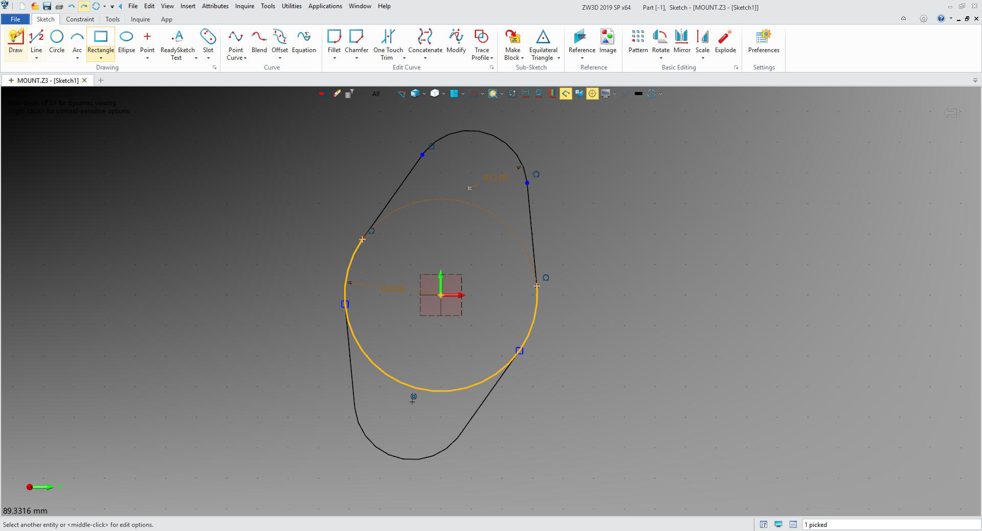
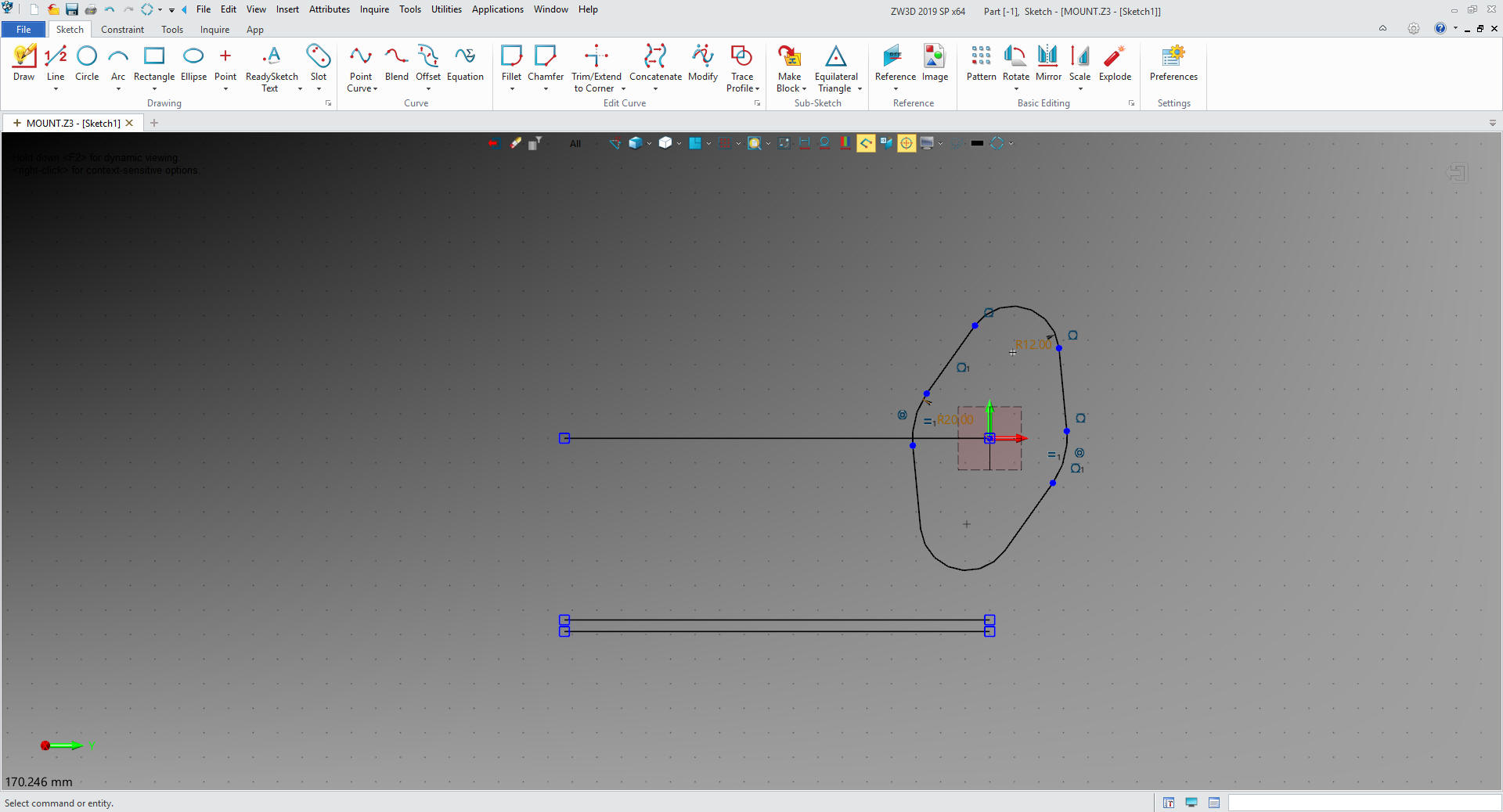
I sent the image on the left to customer and the product manager wondered what the lines
were. I realized that the tangents are only something, we as CAD
designers, know about. So I sent her the image on the right without
the tangent lines shown, she completely understood.
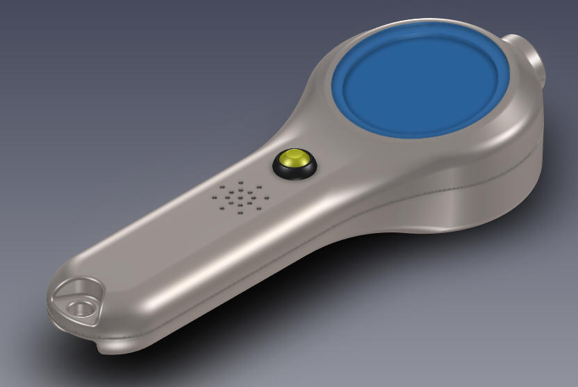
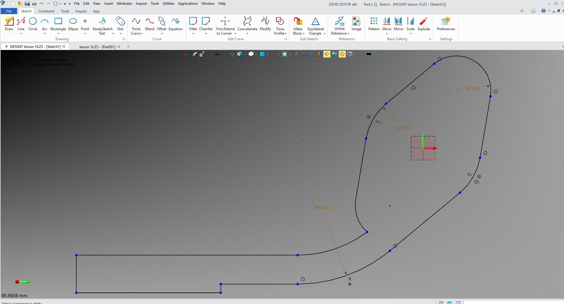
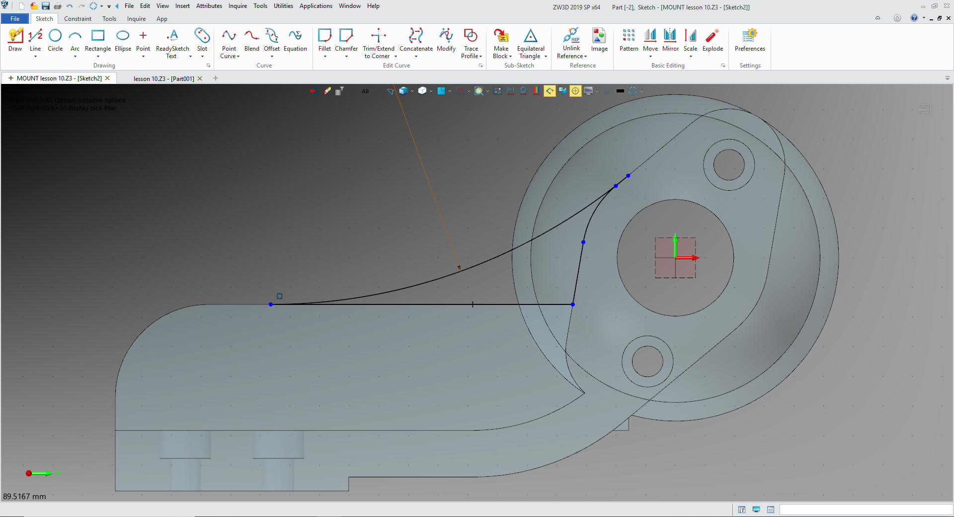
I offset the arc and line 10mm and offset the
50mm line and trim and add the block in back. Notice there are no constraint dimension.
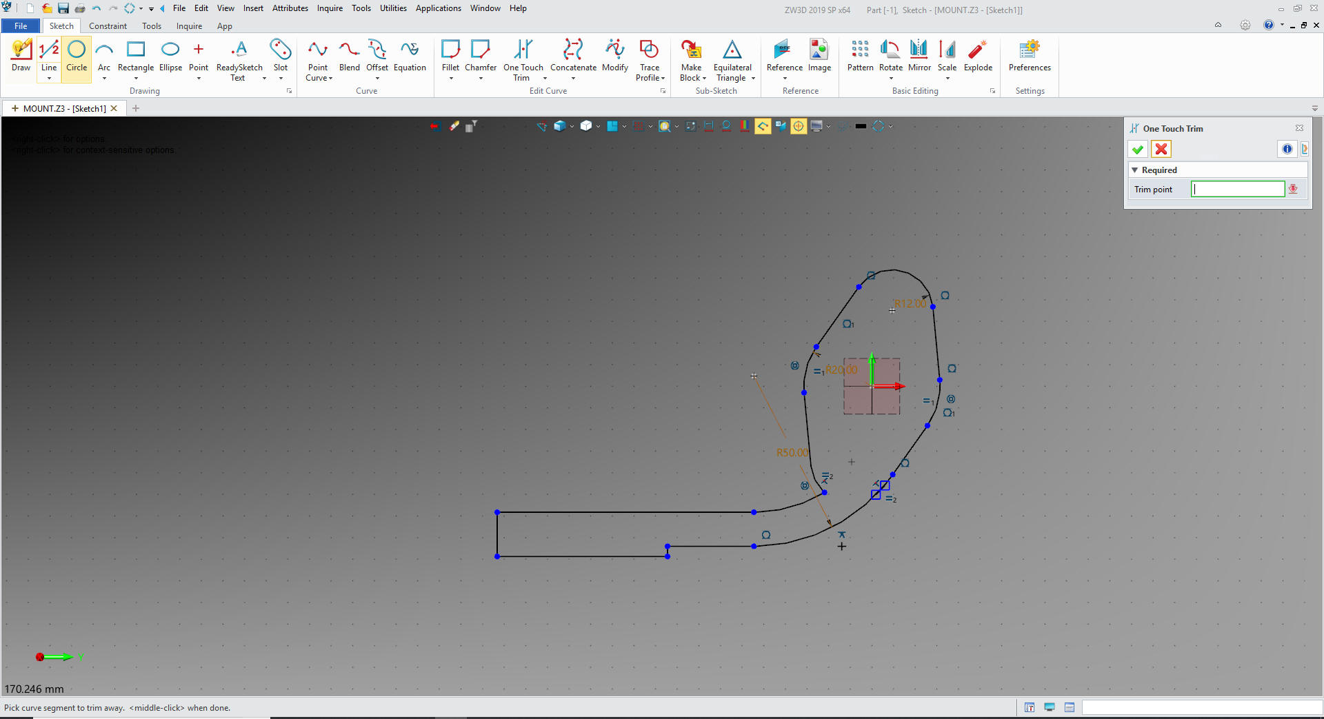
We
exit our sketch and extrude the profile
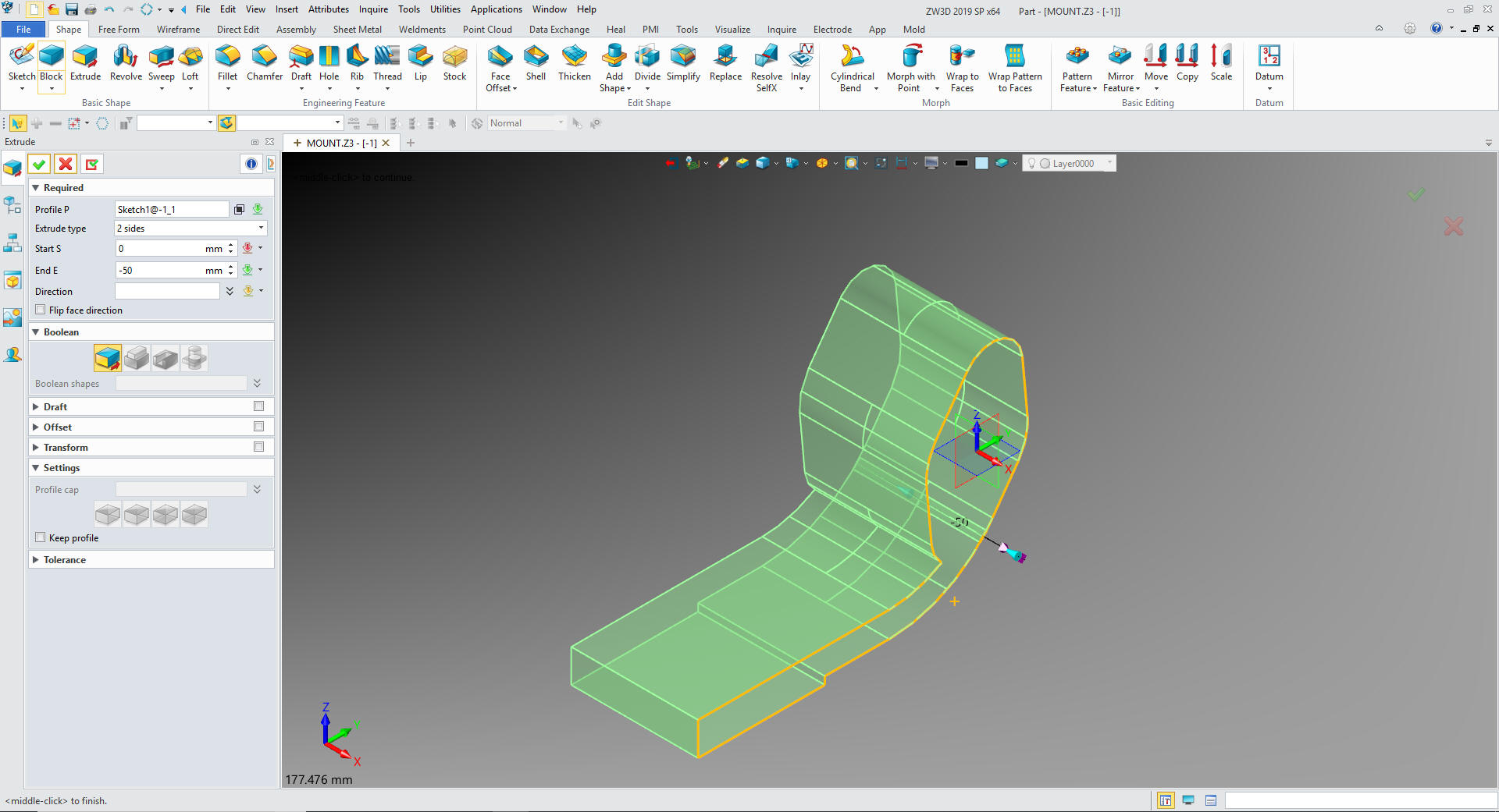
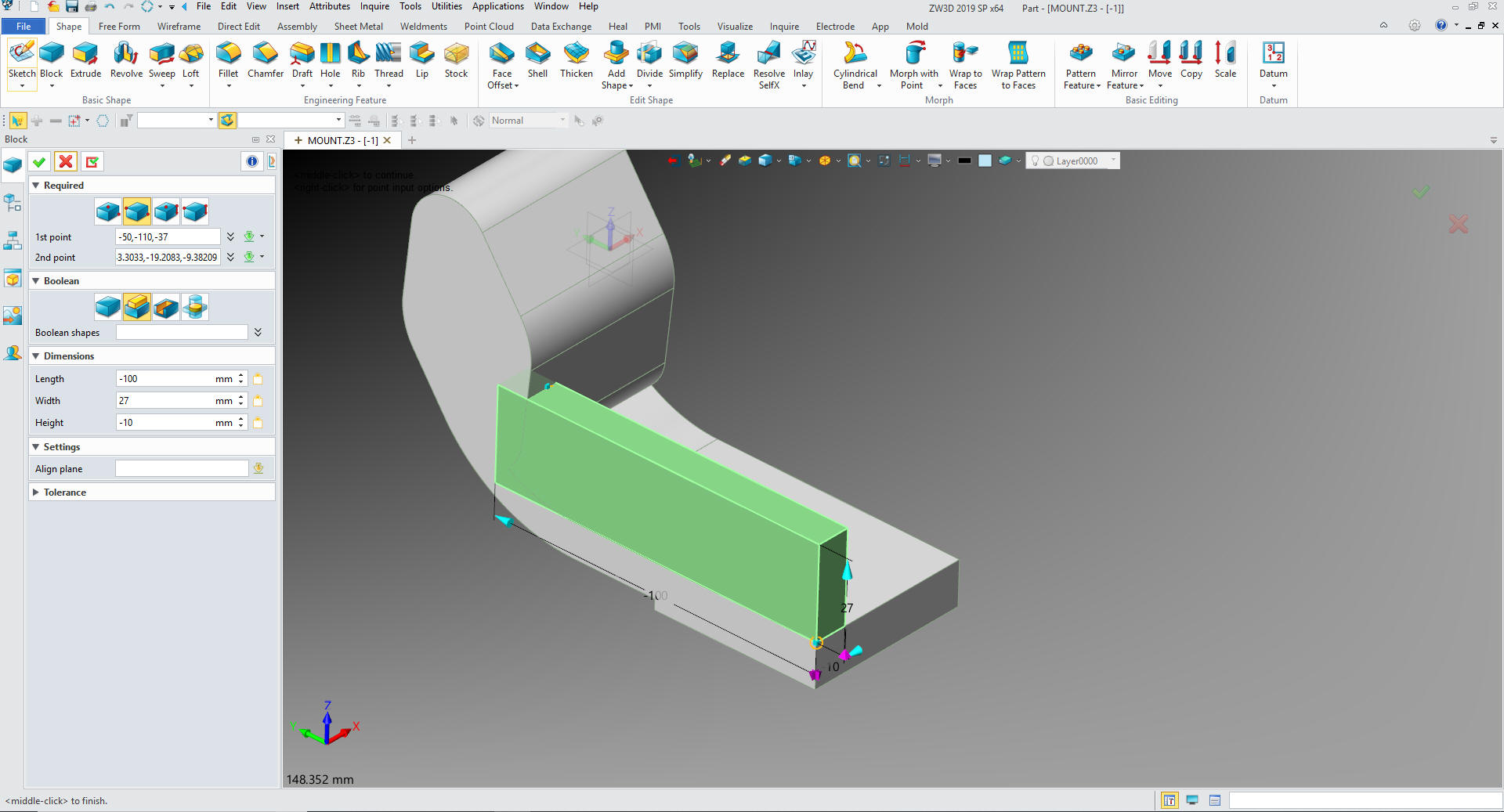
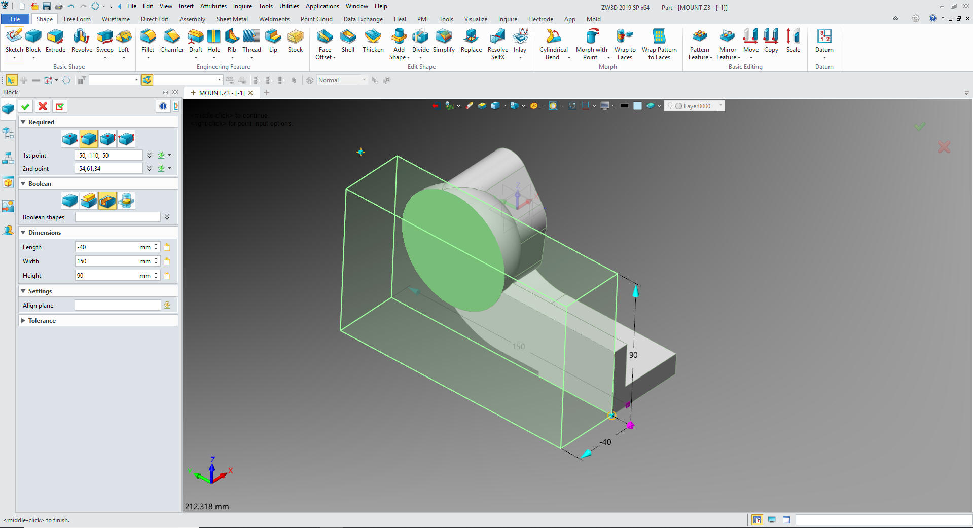
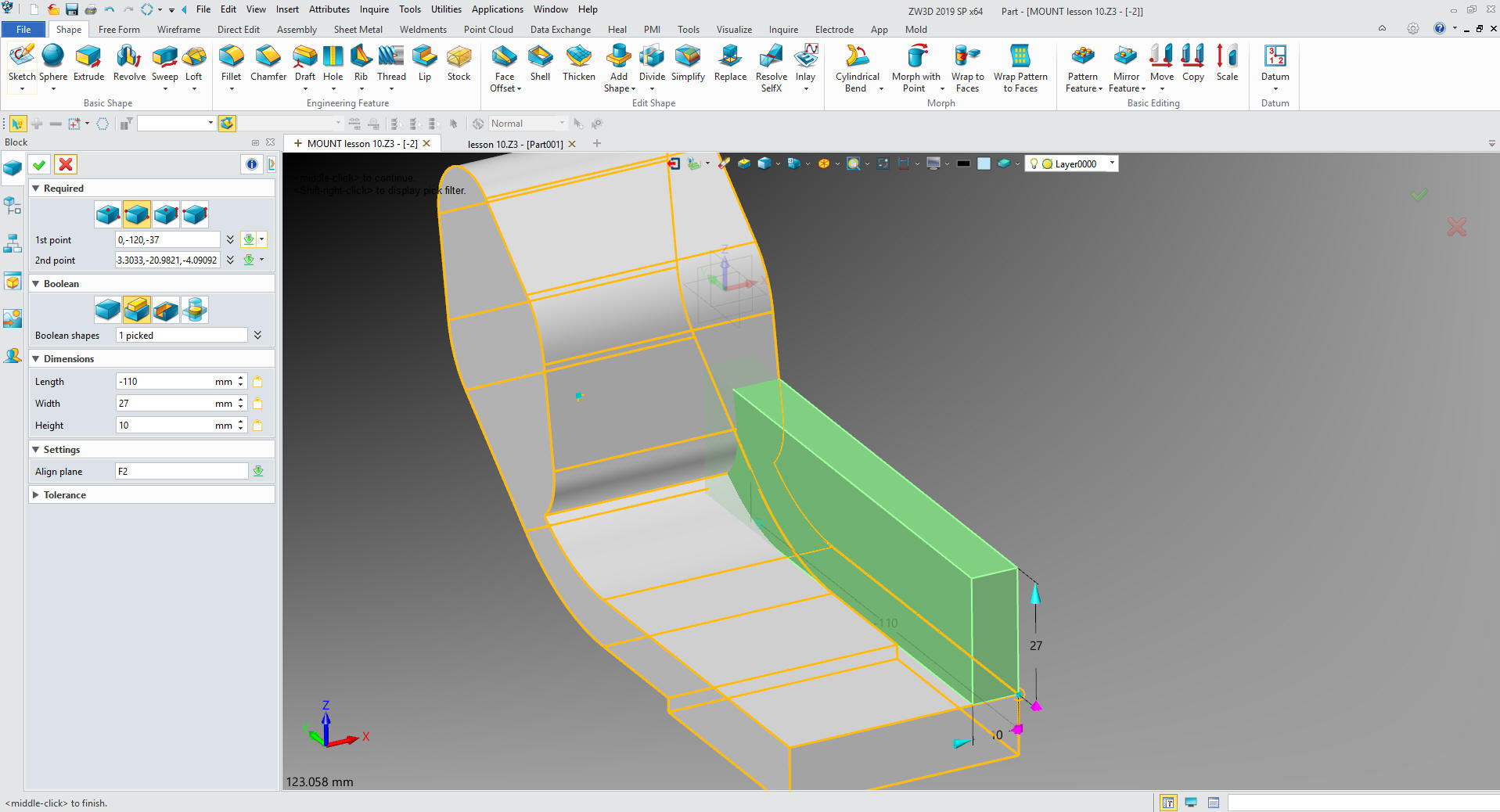
I
will insert a primitive block on the back edge and size it.
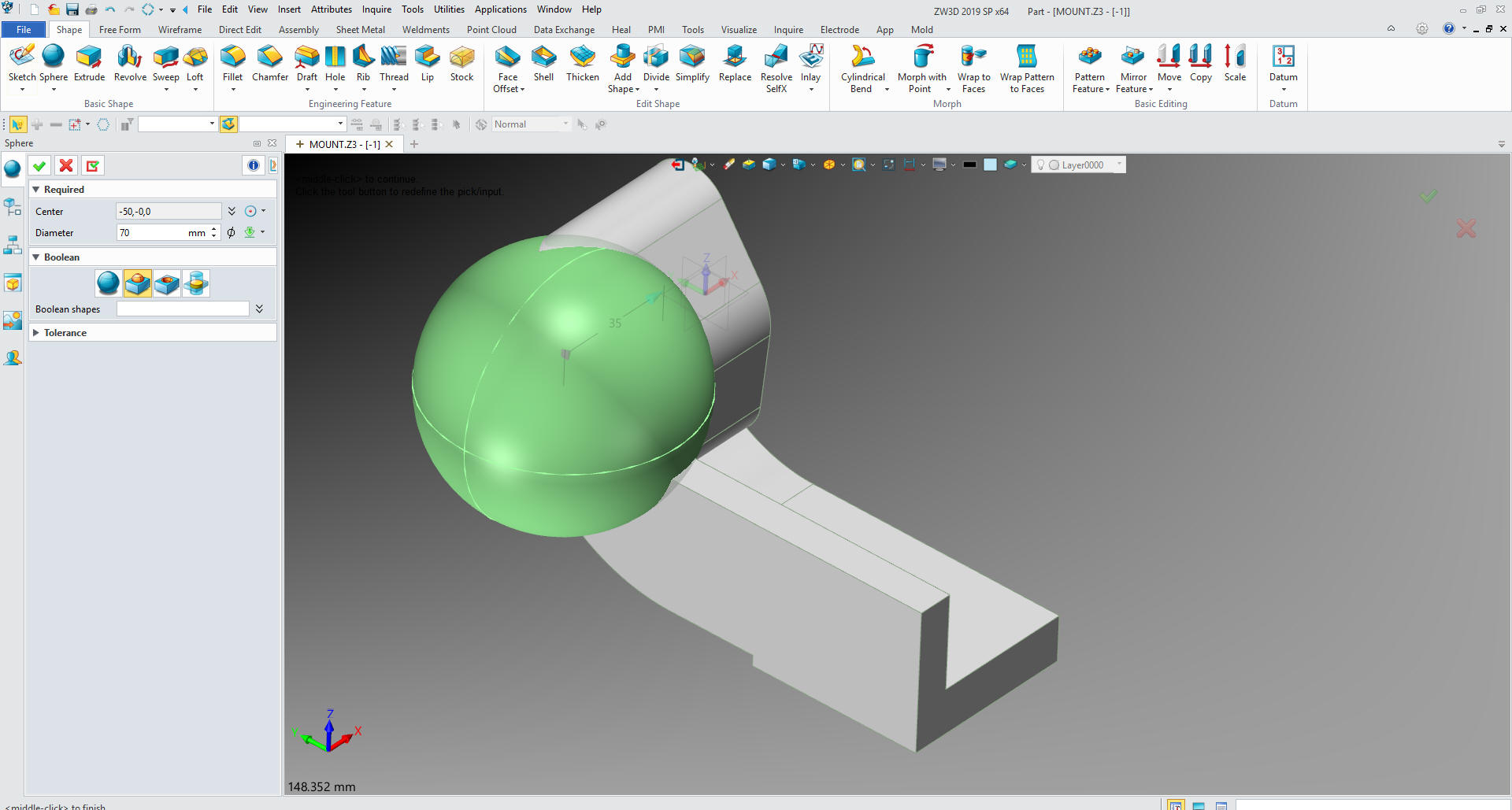
We
drag and drop a primitive sphere to the center of the boss and size it
We
insert a primitive block on the back face and set it to remove.
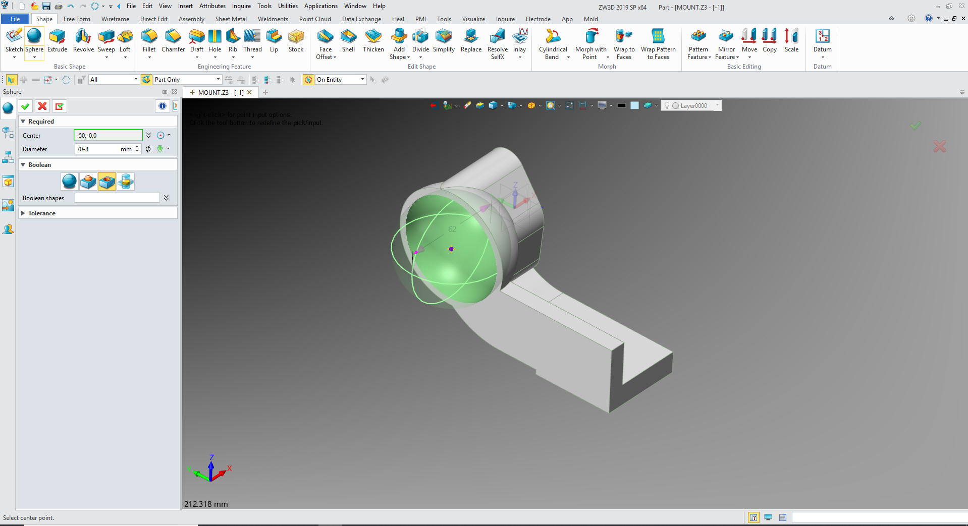
We
insert a primitive sphere to the center of the sphere, size it and
set to remove.
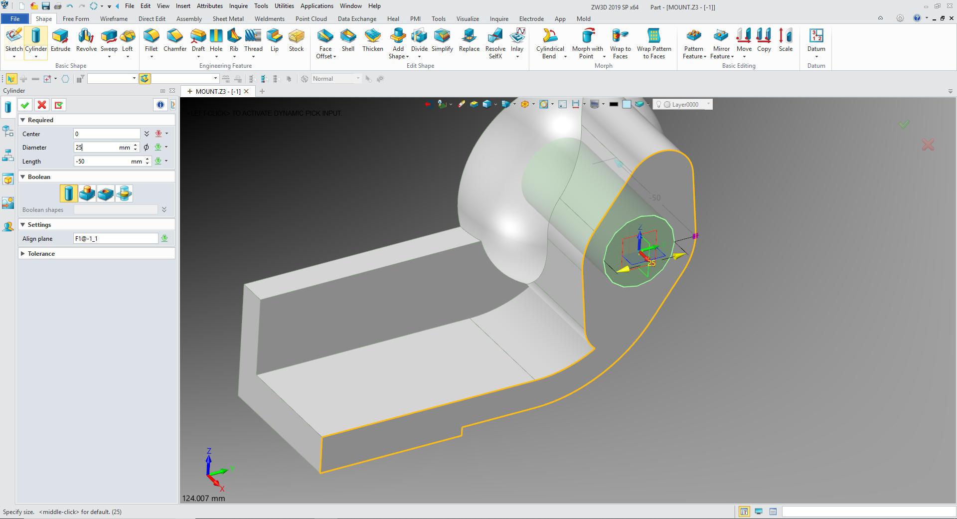
We
insert a primitive cylinder at the center of the boss, size it and
set it to remove.
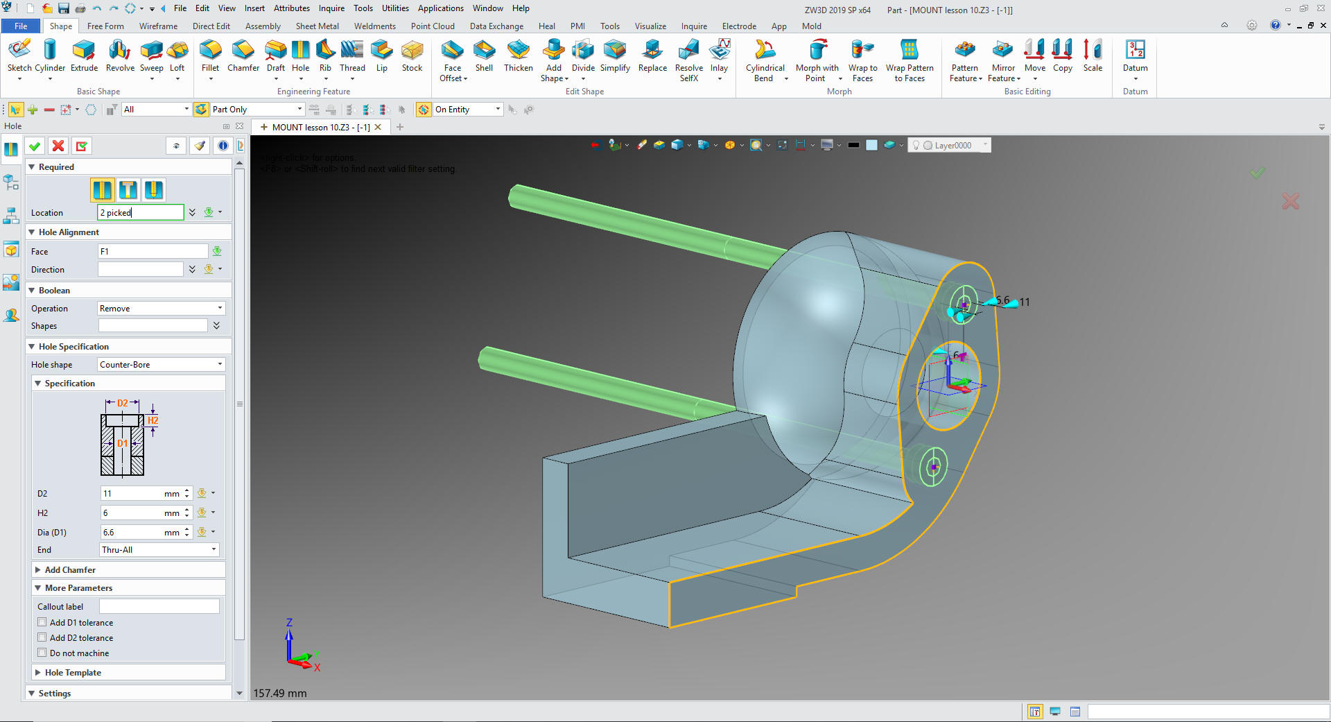
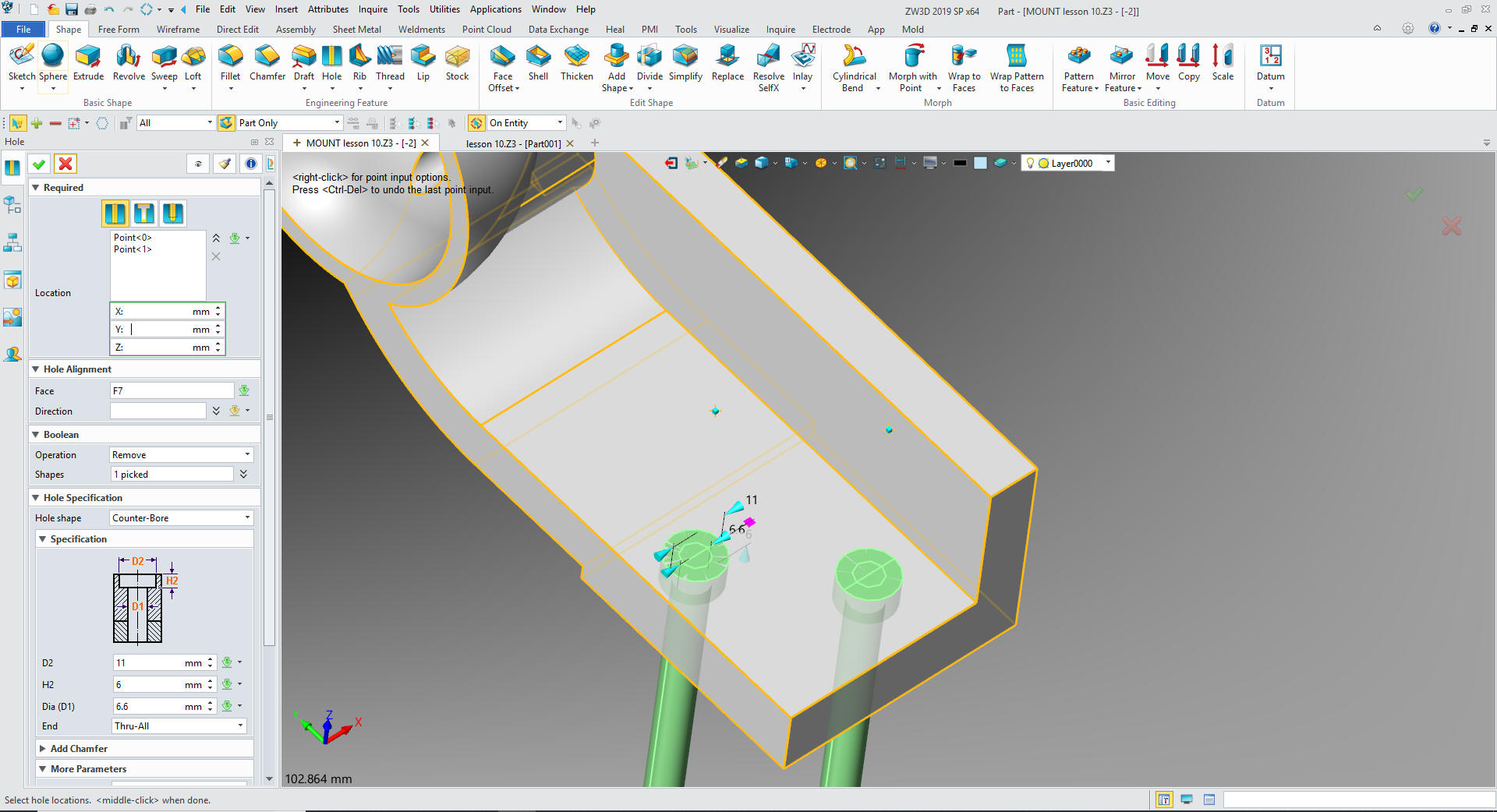
Now
for the counterbored holes. We use the hole feature set the size and
locate on the face of the boss at the centers.
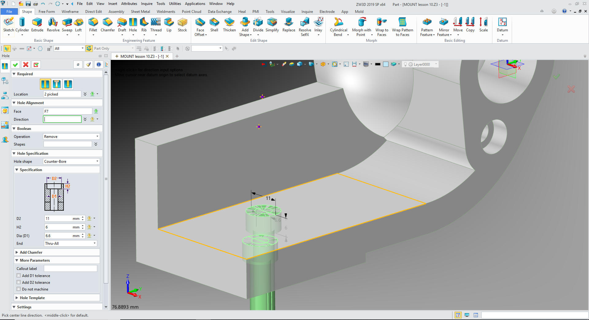
Now
the other two holes
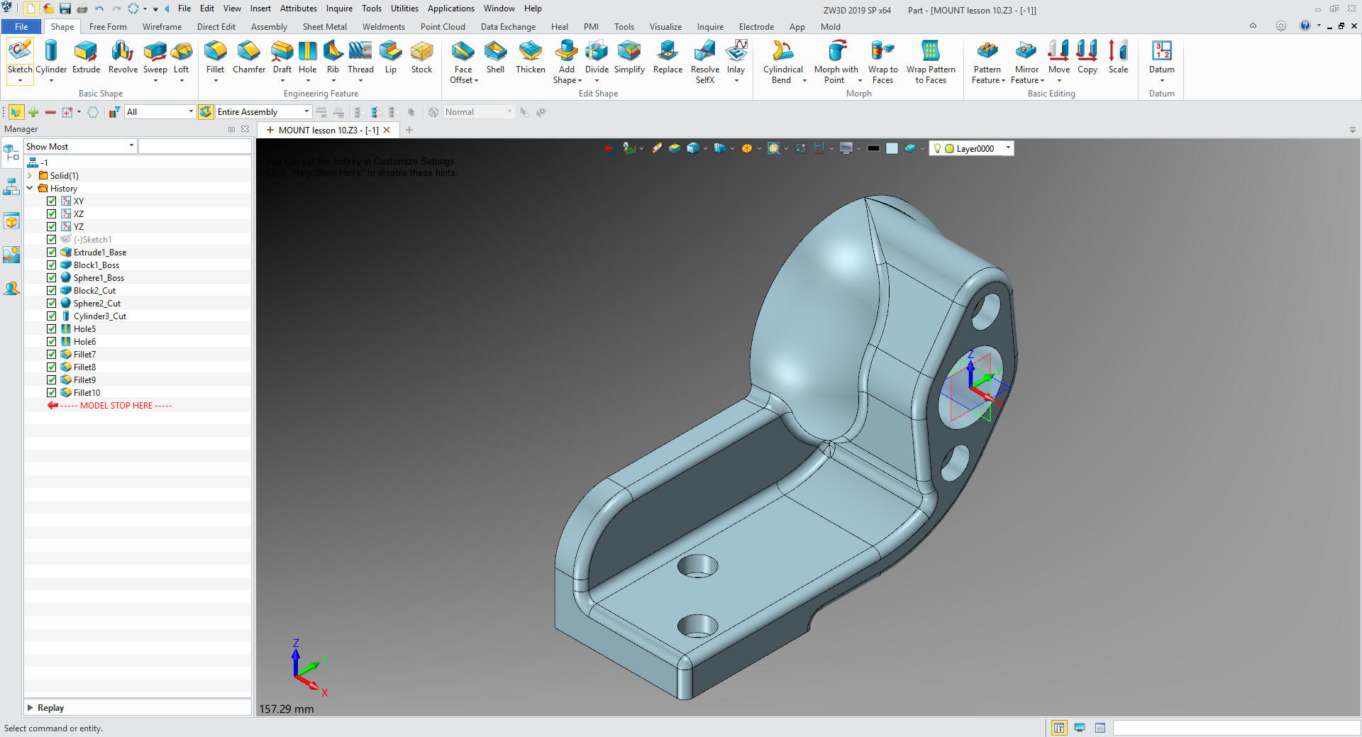
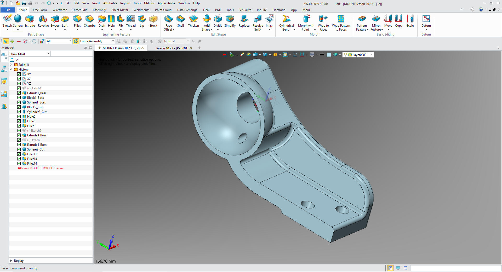
Now
for the fillets and we are done!
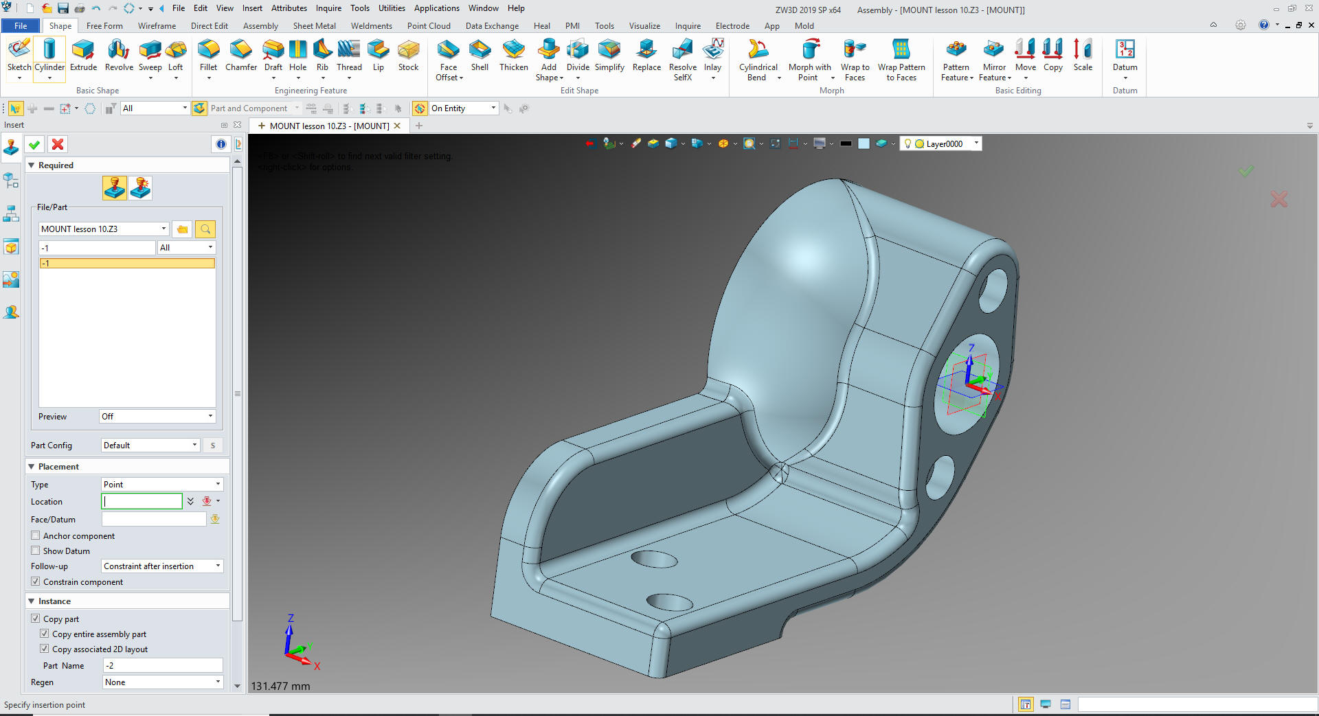
Now
for -2. We will insert a new component under the MOUNT Assembly. We will take the -1 copy it
and name it -2 and locate it to X0Y0Z0
We
open -2 and delete all of the fillets and edit the main sketch. We
rotate the boss 15 degrees.
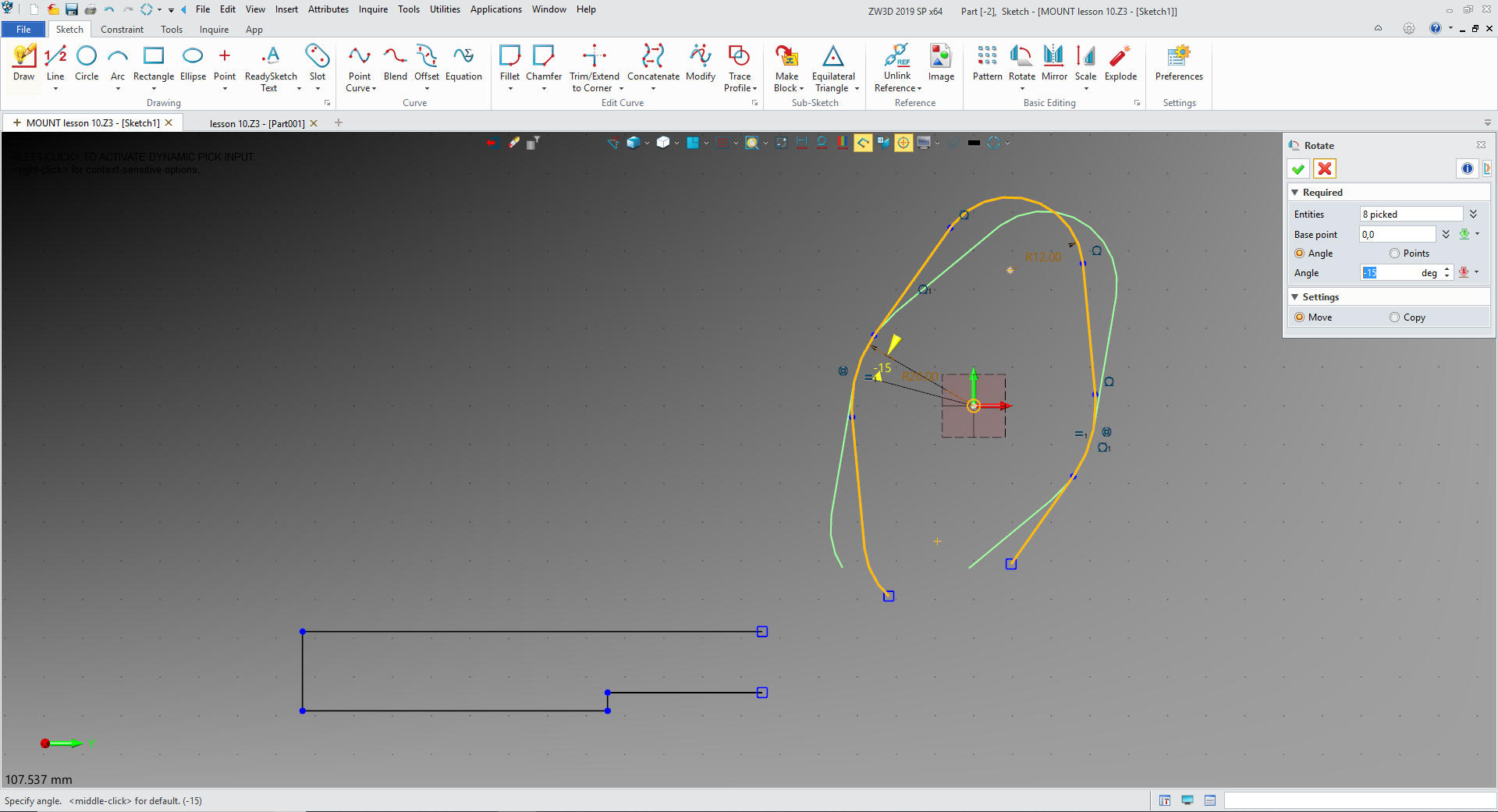
We trim/extend the related lines basically clean up the sketch,
again no constraints.
We
move the block
We
move the holes
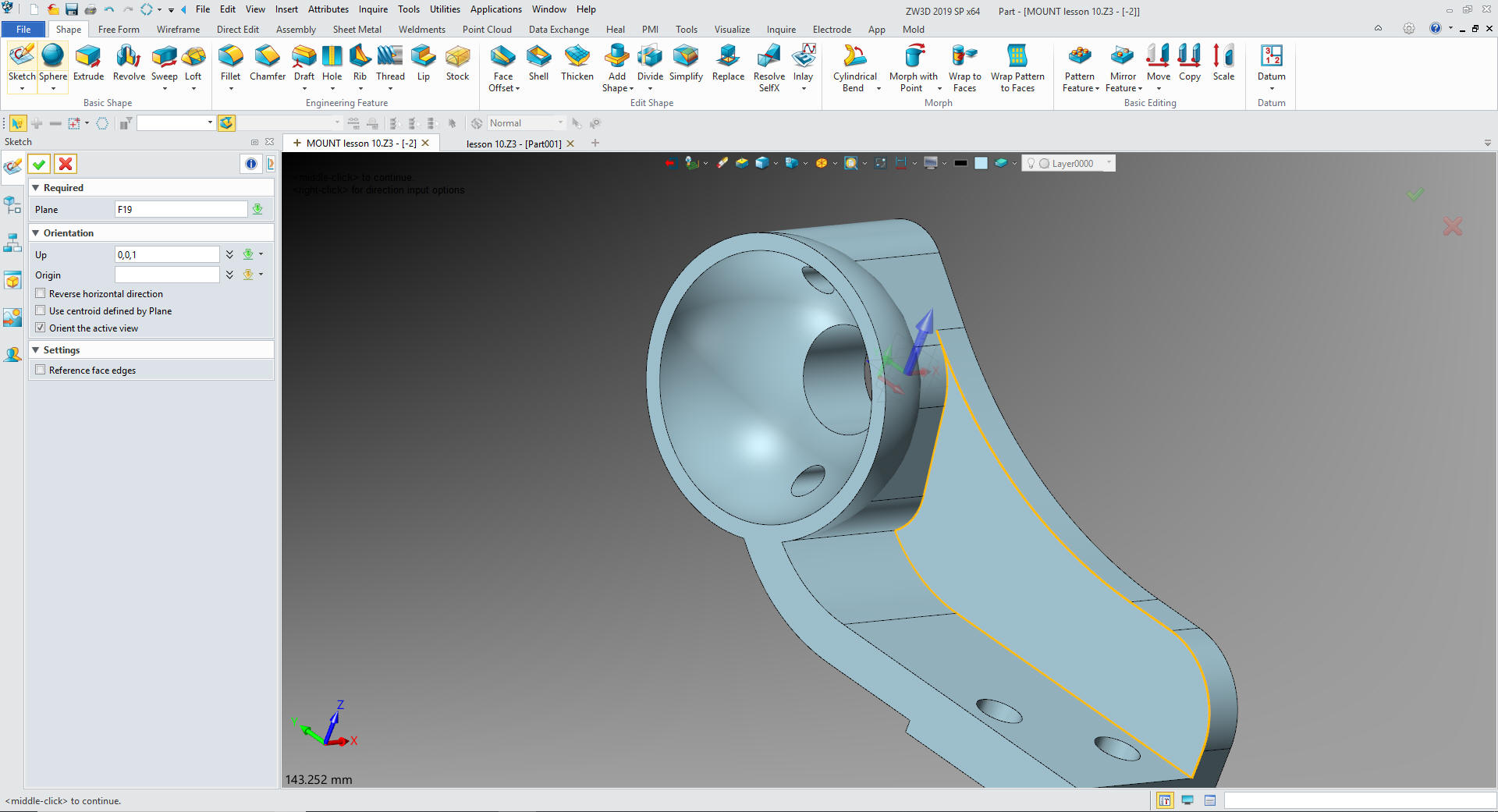
We
create a sketch on the boss and select Y as up. Create a small
wedge.
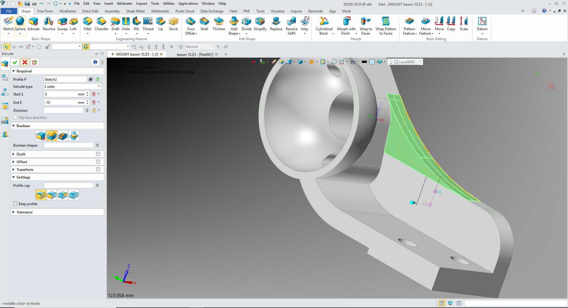
We
exit the sketch and extrude the profile
One
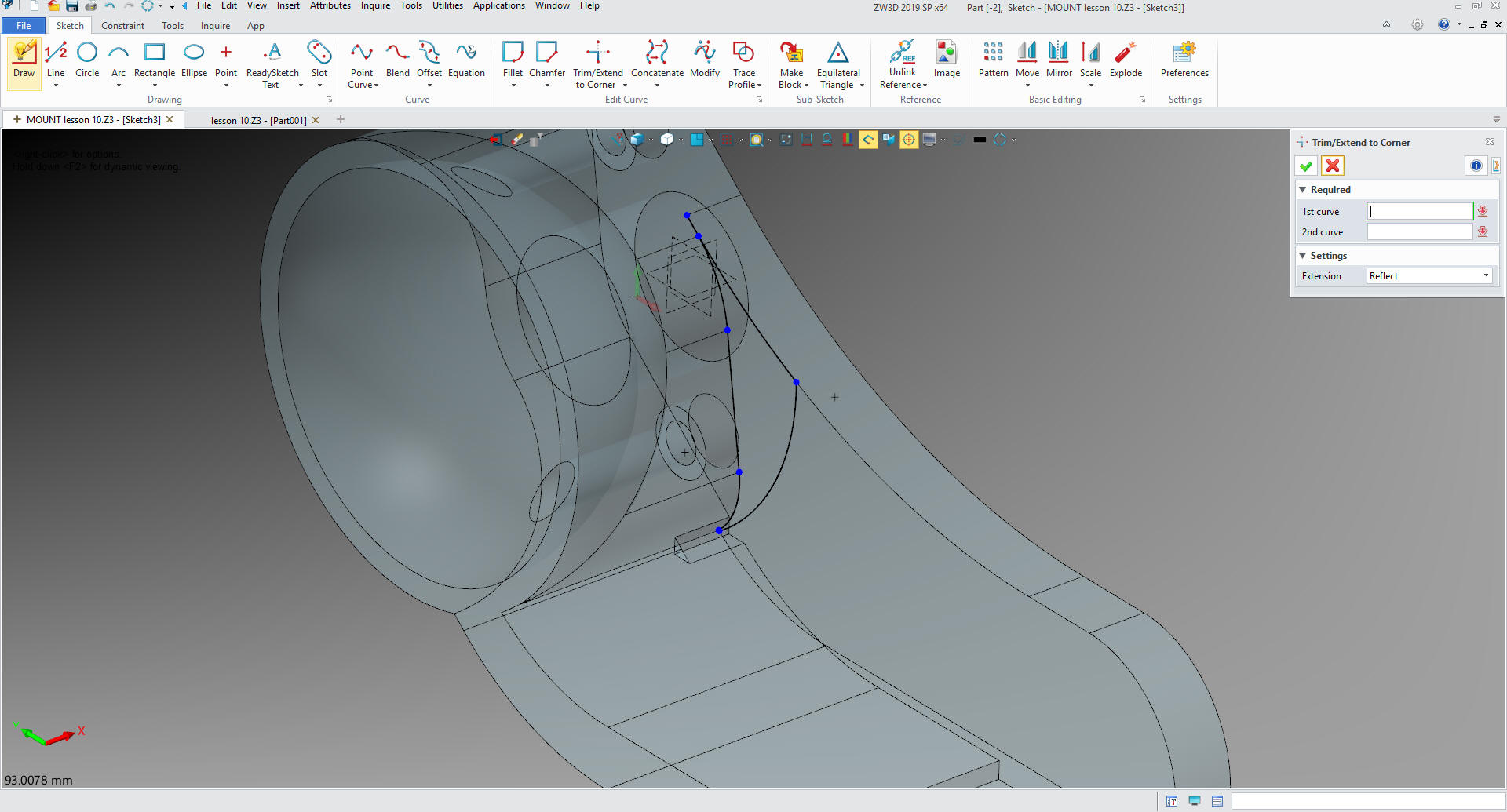
more sketch. Selecting the inside face select Y as up.
We
use reference curve to define the edges.
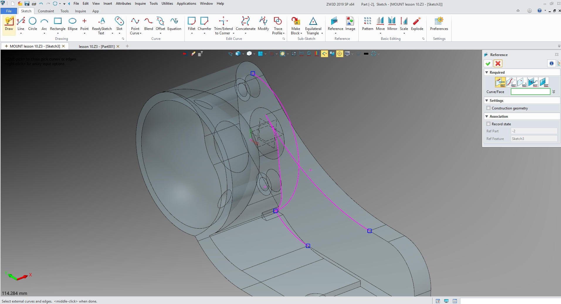
We
unlink them converting them into usable entities. We trim the sketch
again no constraints.
We
extrude the feature.
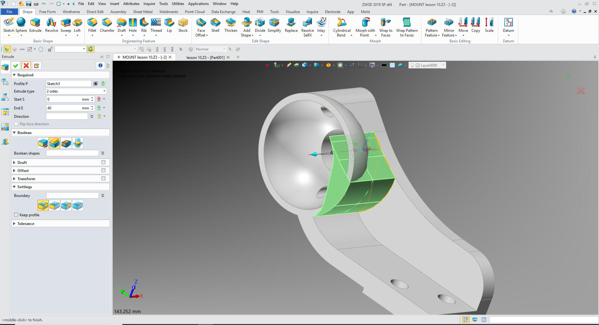
We
notice that the extrusion is in the sphere.
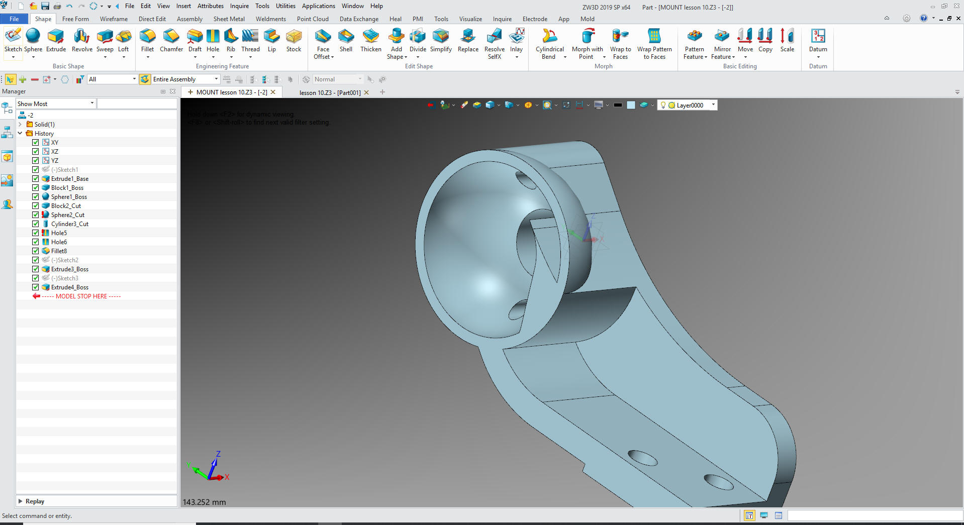
We
just move the sphere cut to the end.
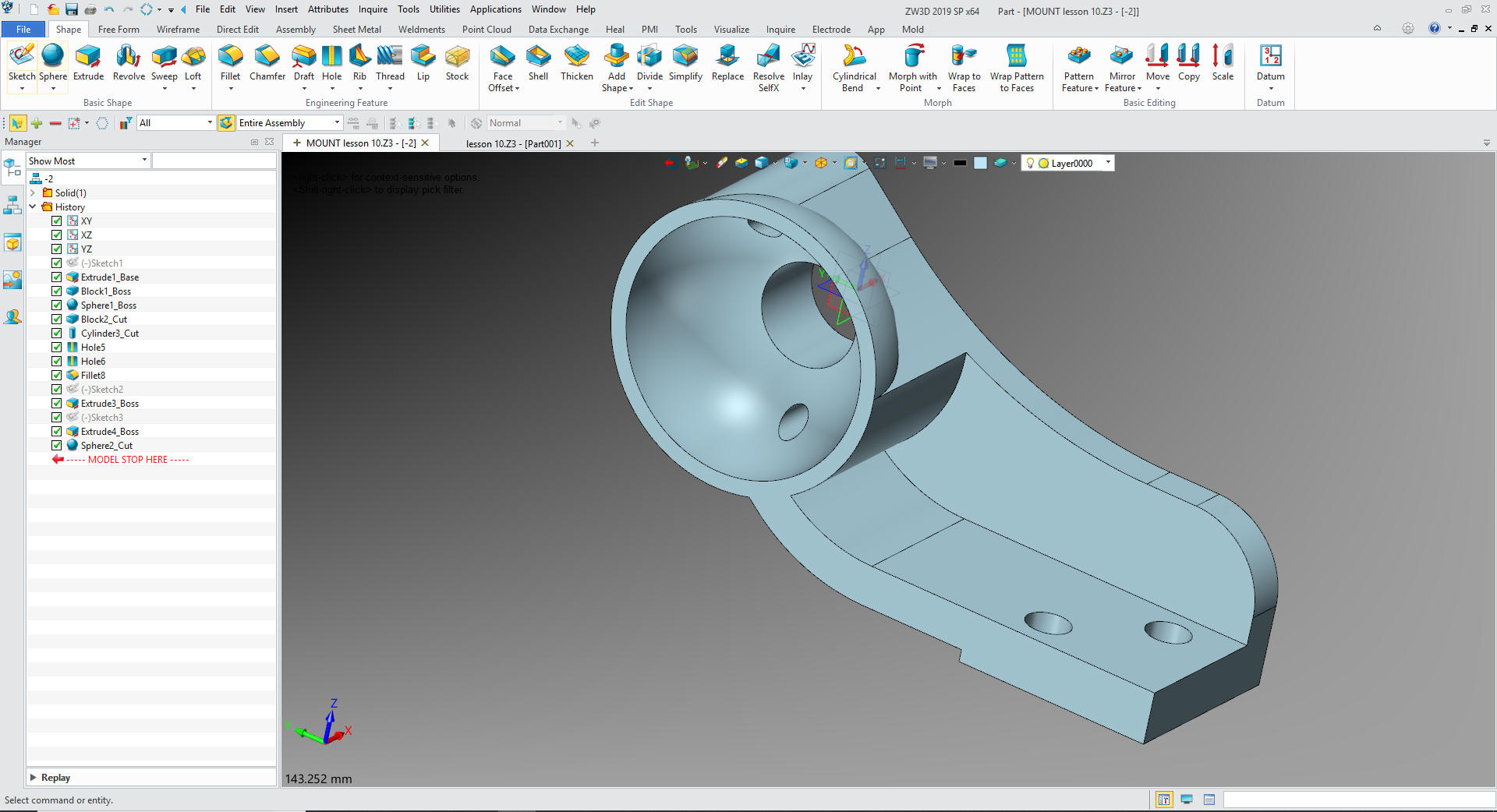
Now
for the fillets and we are done
Oops
we didn't rotate the bottom Hole in the boss. Will delete the bottom
hole and use the rotate pattern feature to create the hole.
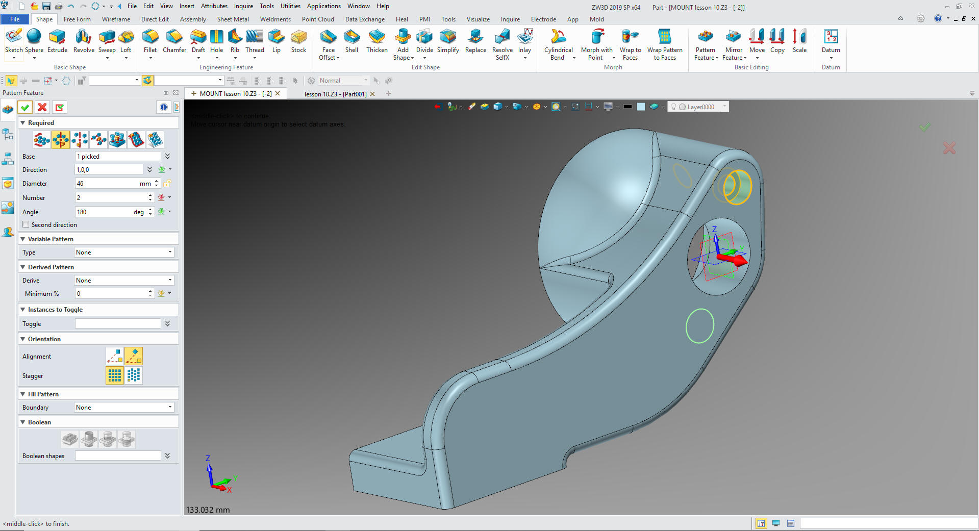
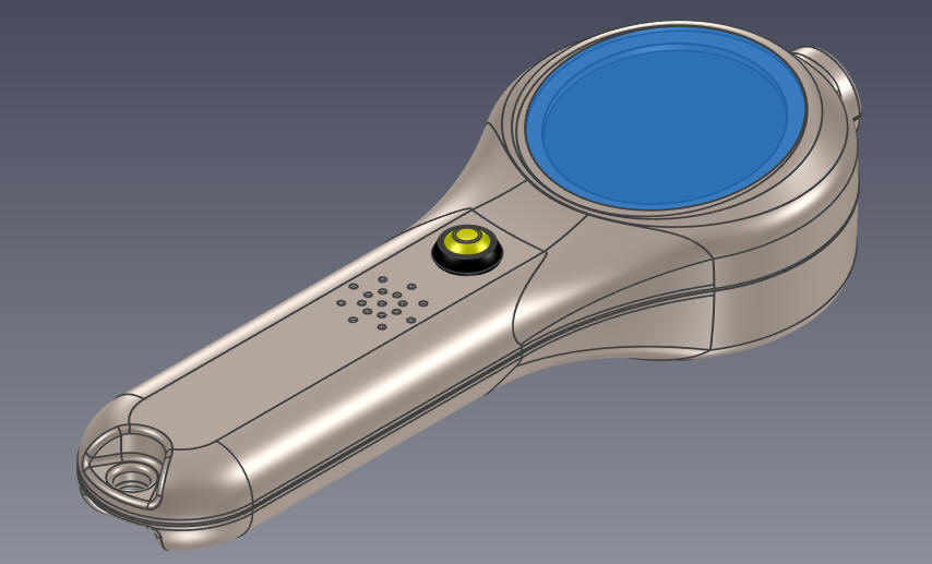
Now
we are done.
DIRECT EDIT MODIFICATION
I thought it would interest you to make the changes by direct
edit. Now this is a very simple model and you could easily recreate
with just using features. But I thought this would be fun.
IronCAD is the only integrated history/direct edit based system. NX
and Solid Edge have given it a try but fall far short due to their
dependence on previous history so let's take a look.
You can see in this article the extensive experience I have with
direct edit.
Using Multiple 3D CAD Systems
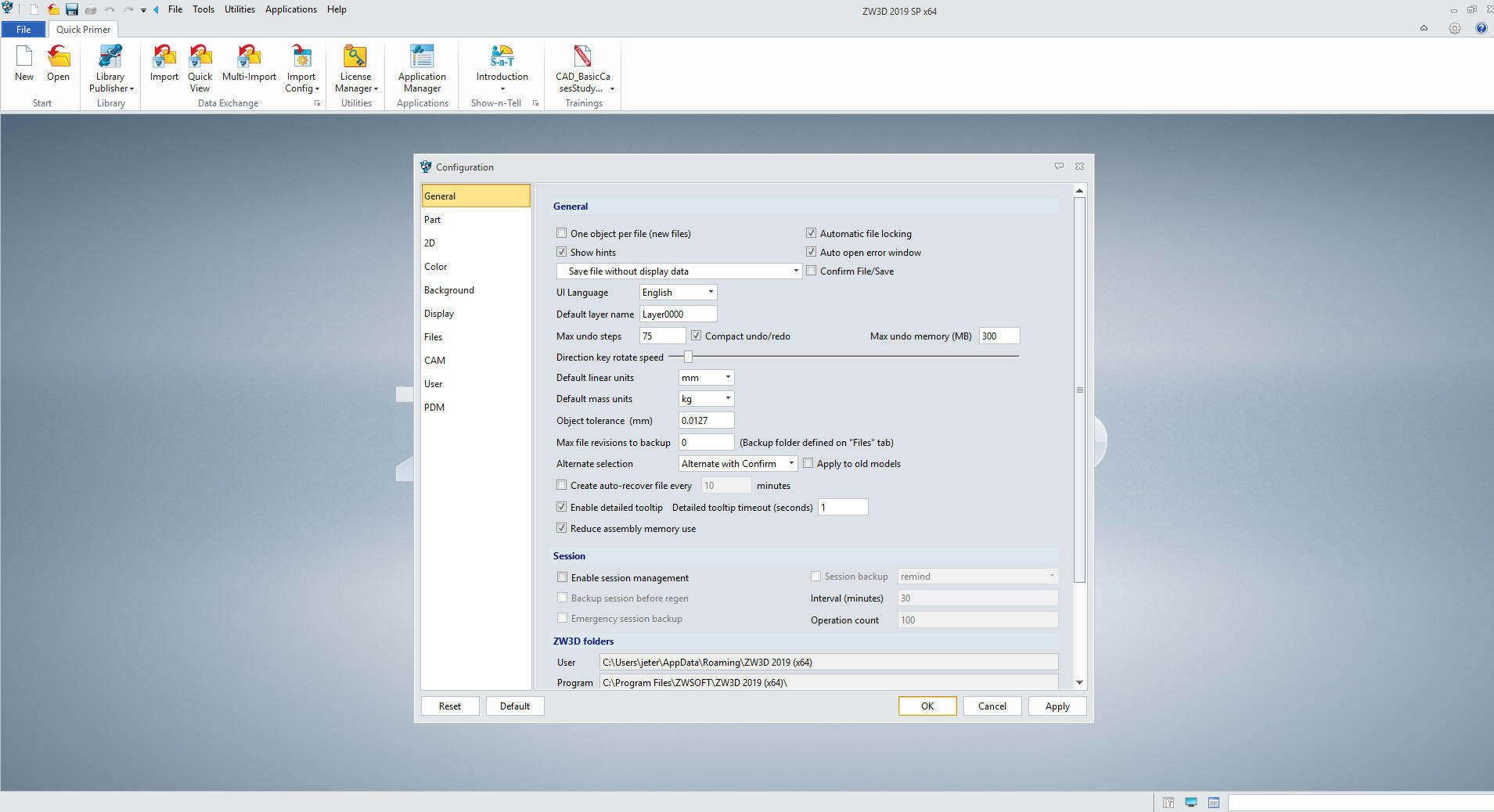
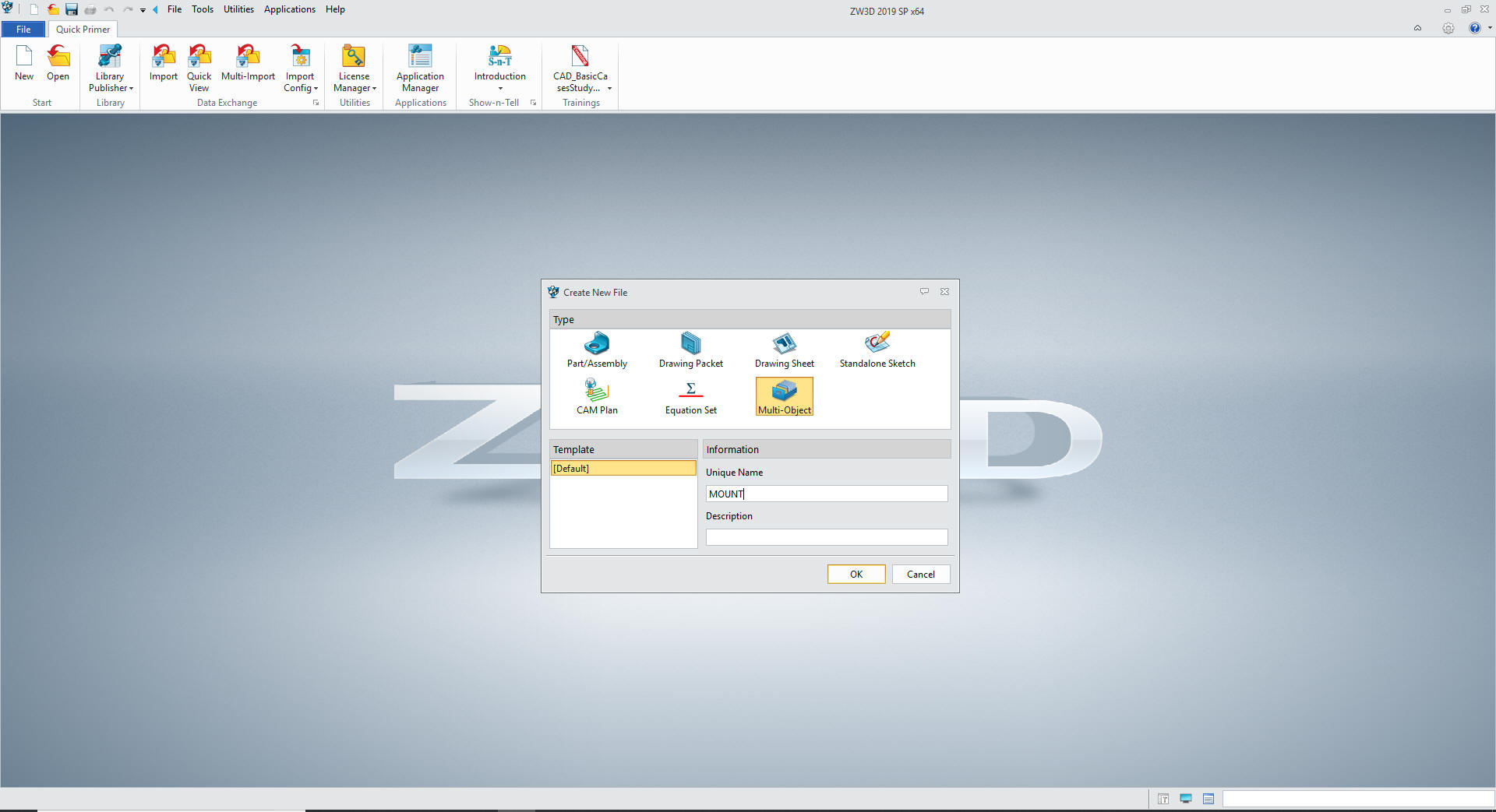
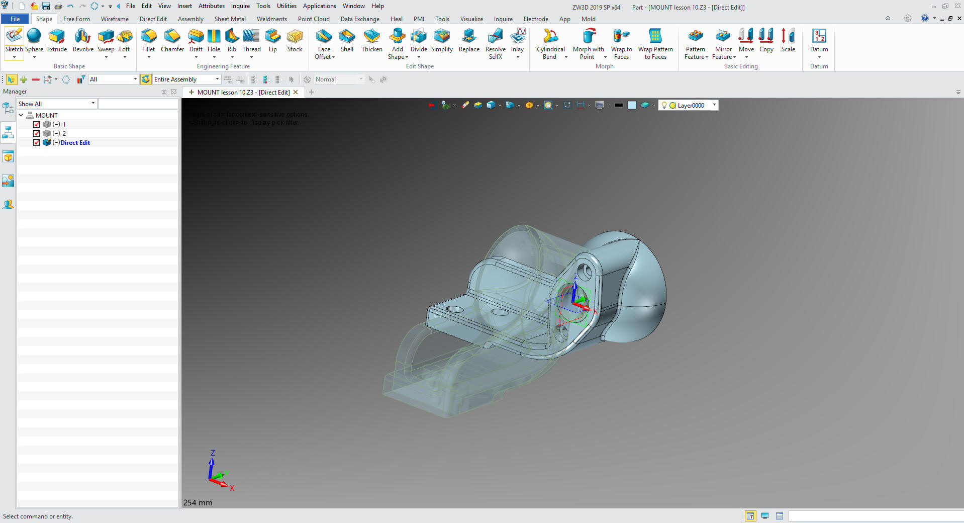
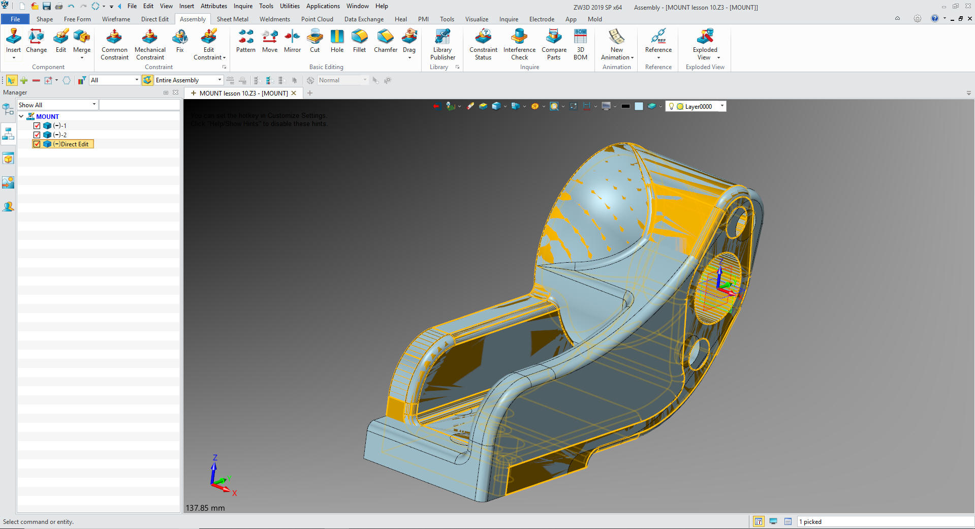
The first thing we need to do is insert a component under Mount
and name it Direct Edit. I really have to reiterate that the
Multi-Object environment is by far the most productive feature in
ZW3D along with the integrated drawing.
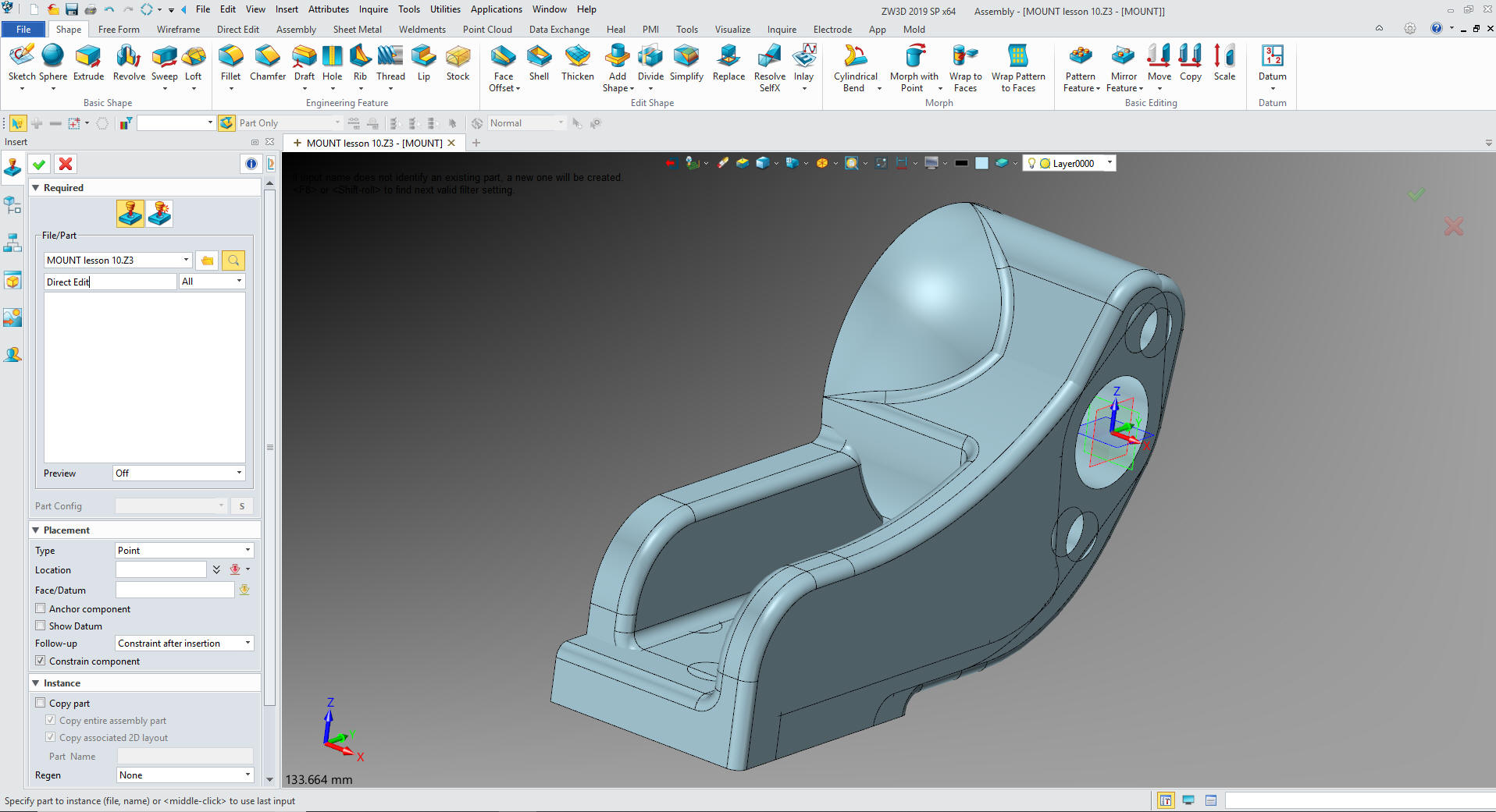
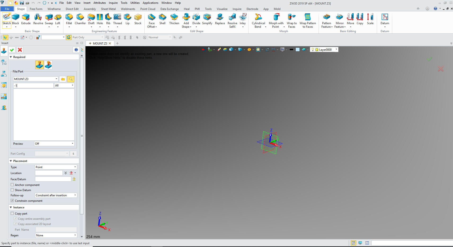
We will import the new part and import a STEP file of the
original part that was generated in IronCAD. It comes in at X0Y0Z0.
I rotate it, because I want all of the parts in the same
orientation. We go the the top assembly and go to the assembly menu
to move the part.
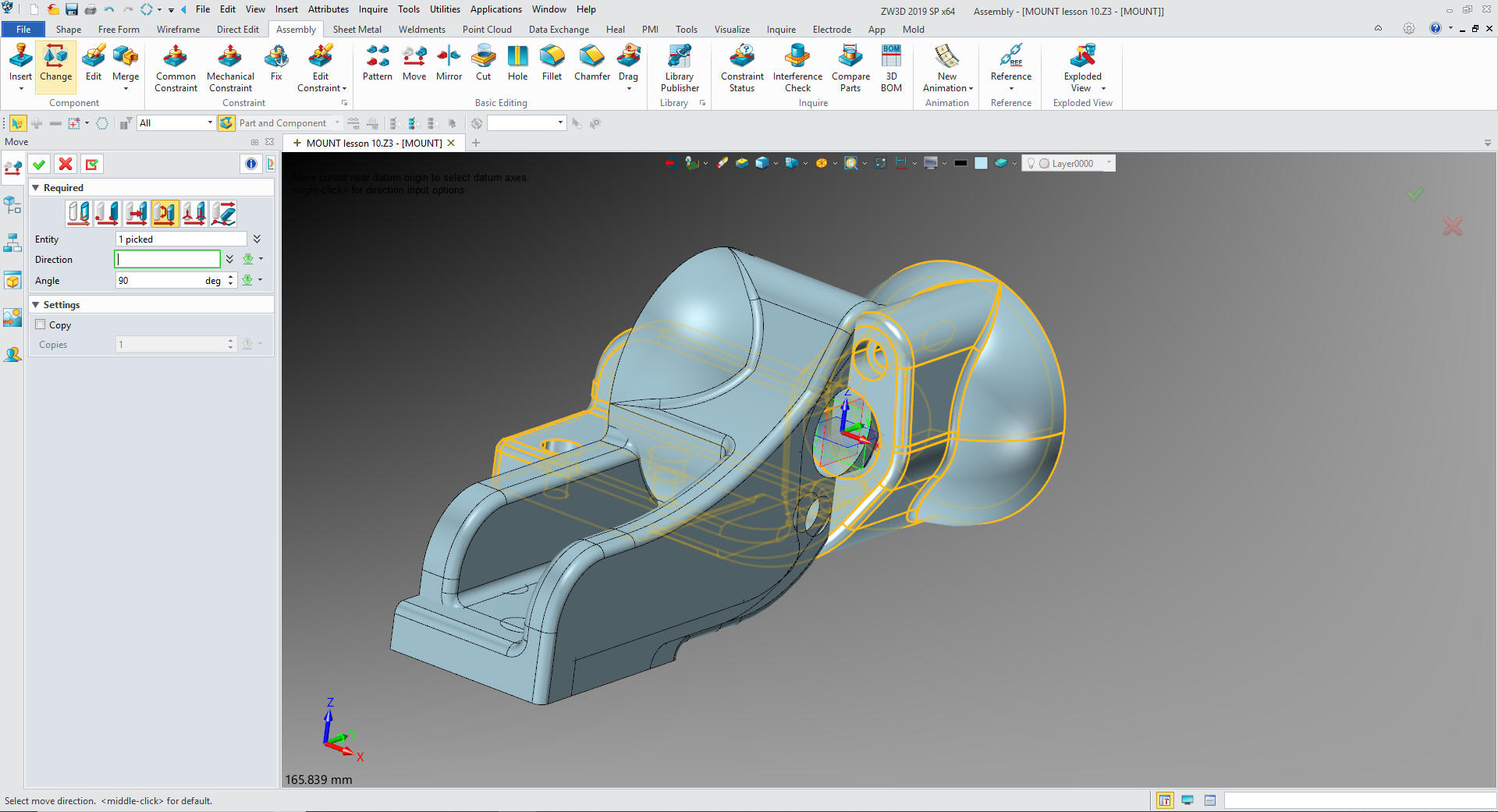
You can see it matches -1.
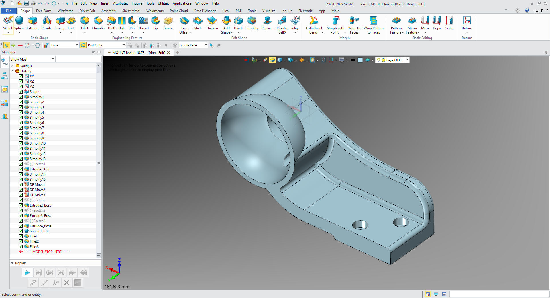
We
will open Direct Edit and the first thing we do, like when just
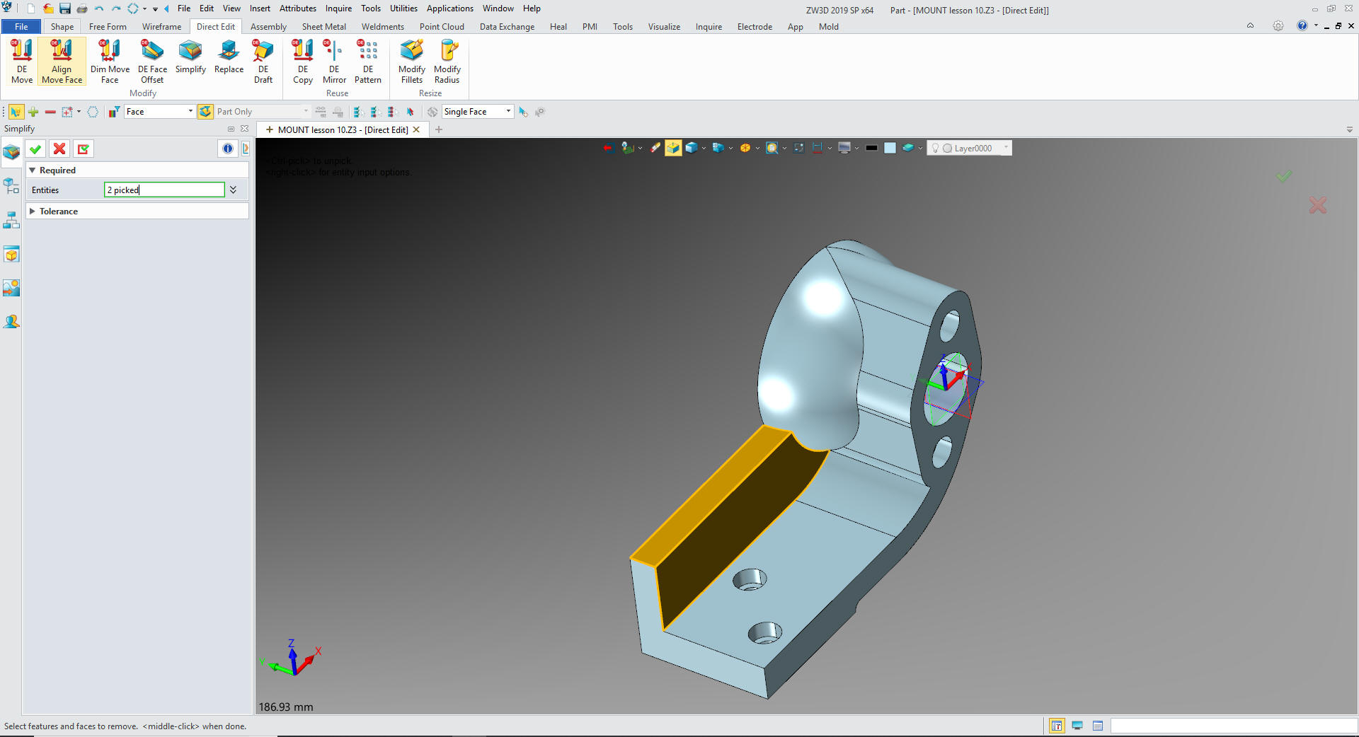
modifying a part is to delete the blends. We turn on Direct Edit
function and go to the Direct Edit menu. We use the simplify option
which deletes the fillets and other shapes.
This may take a
bit of investigation. I found these were the first blends to delete
and the rest fell into place.
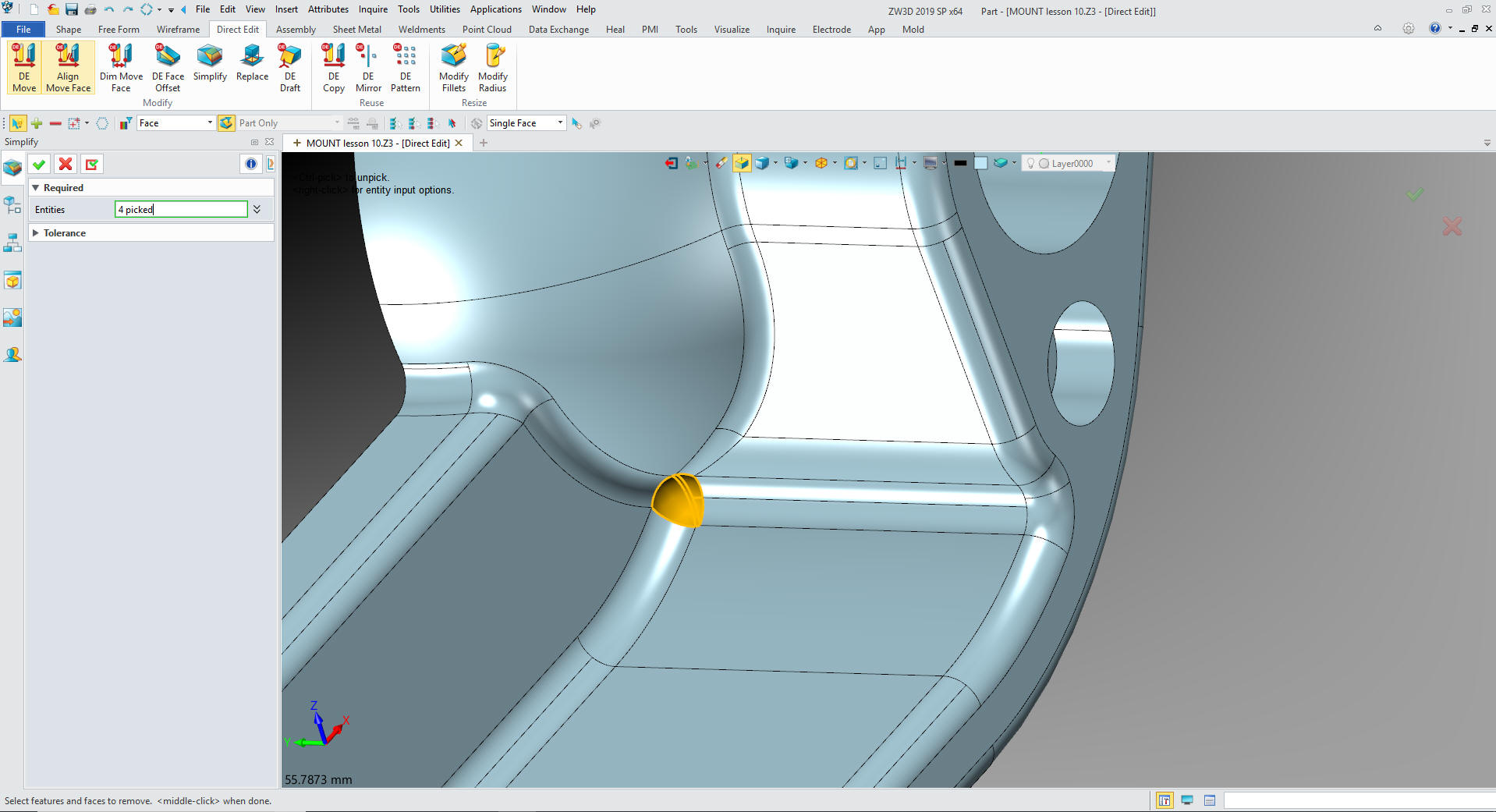
It is
a bit of hit and miss, but it gets done.
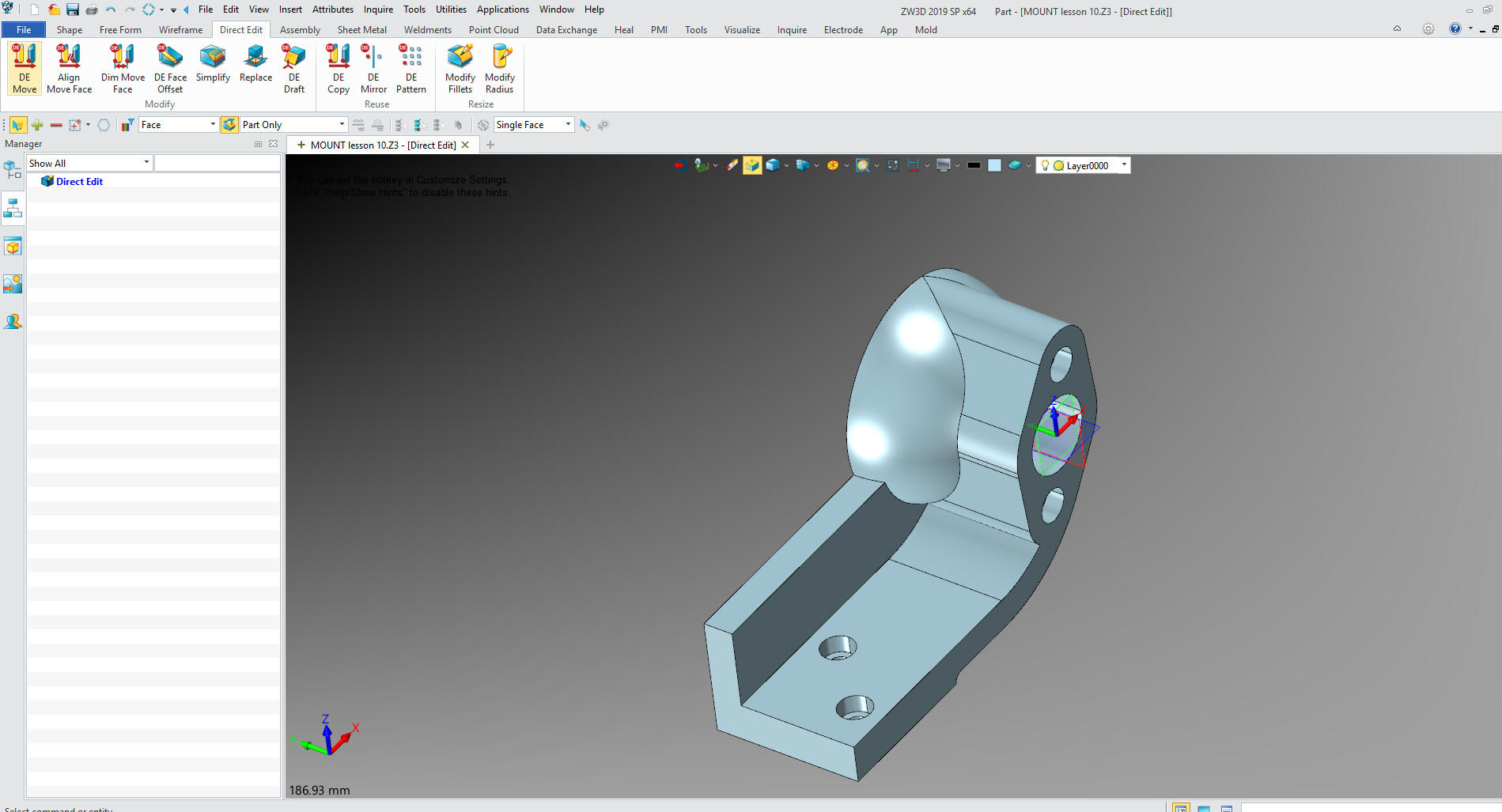
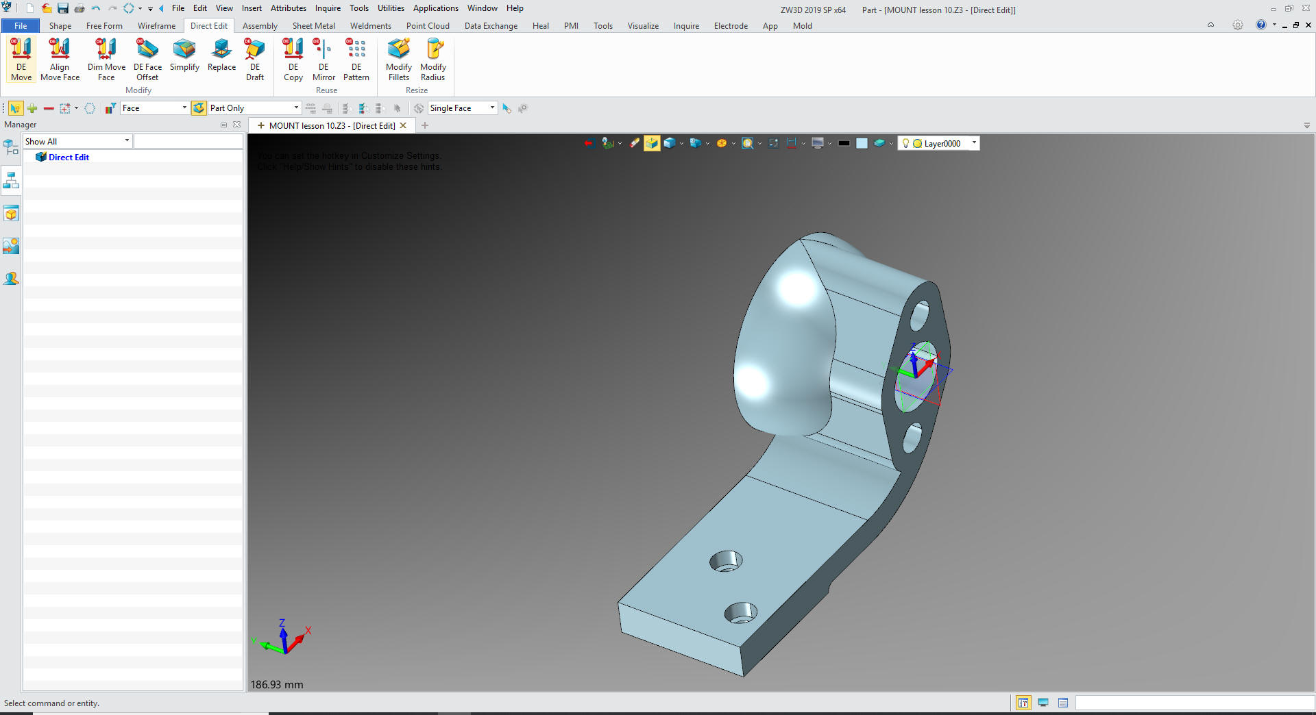
Now
to get rid of the wall again with the simplify command.
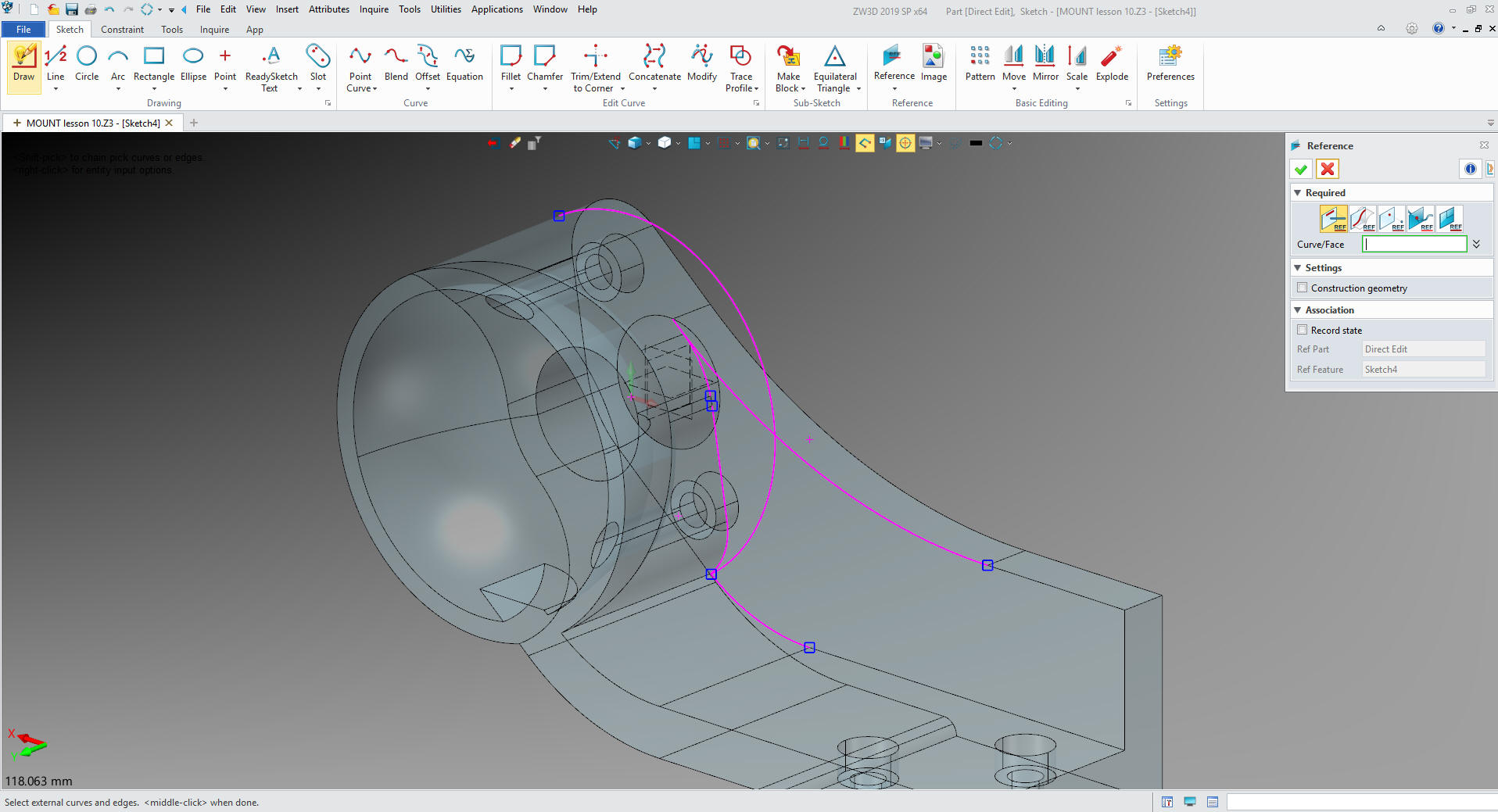
With
that gone we need to isolate the boss and sphere for rotation.
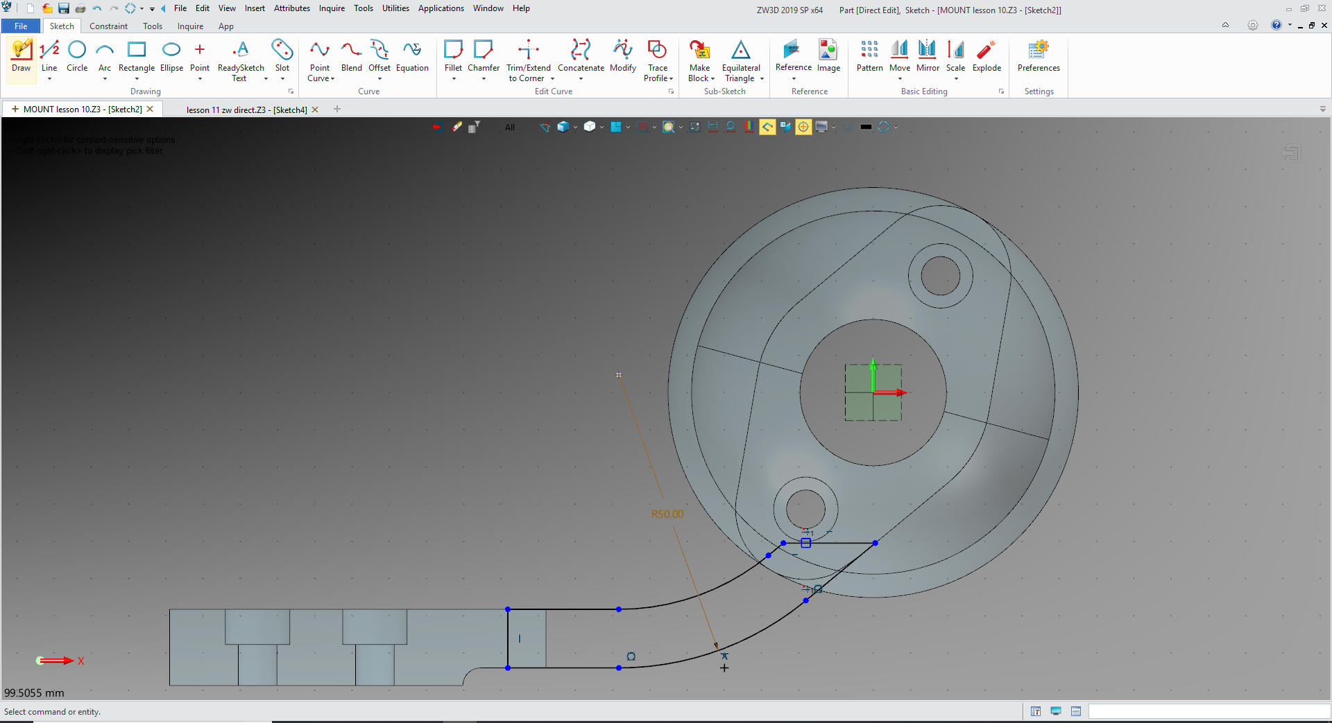
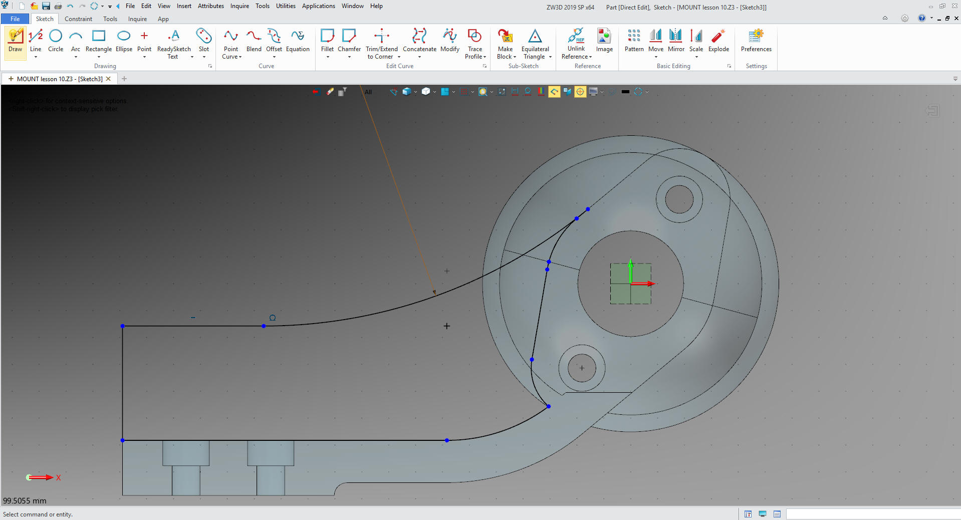
We need to make a sketch and trim the model close to get faces that
can be easily simplified (deleted). We project some reference edges
and create an offset.
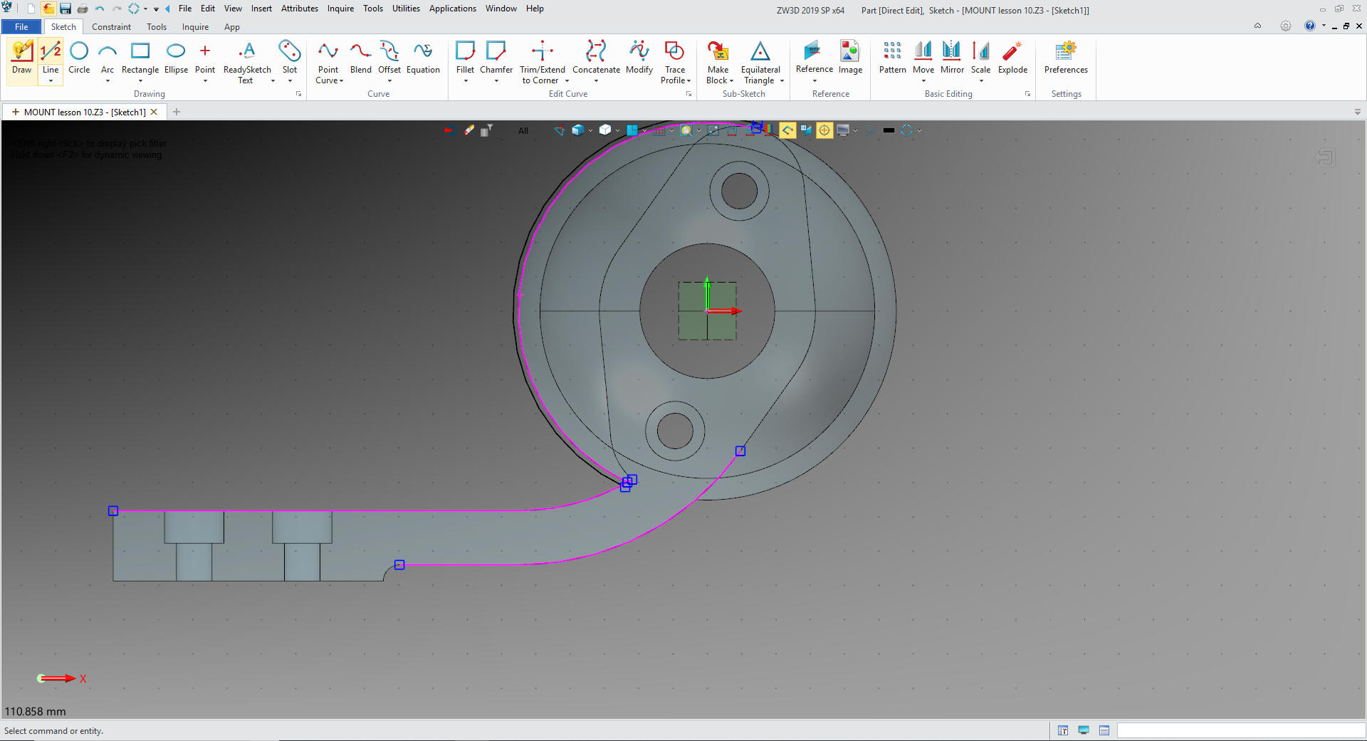
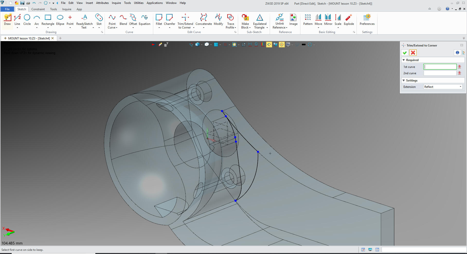
We
convert the reference entities to usable entities and trim or extend
adding the line outside the tangent. Again there are no constraints.
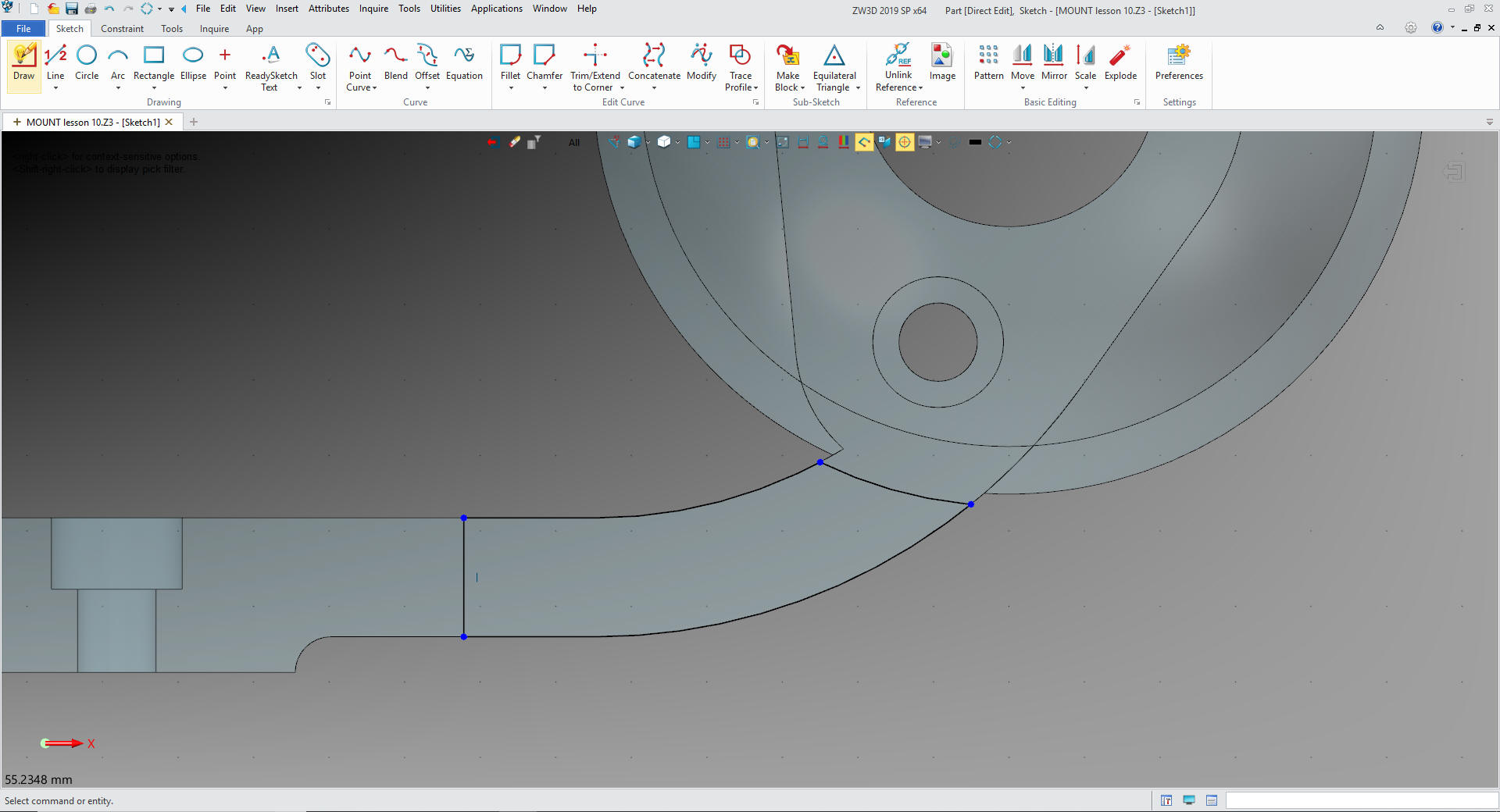
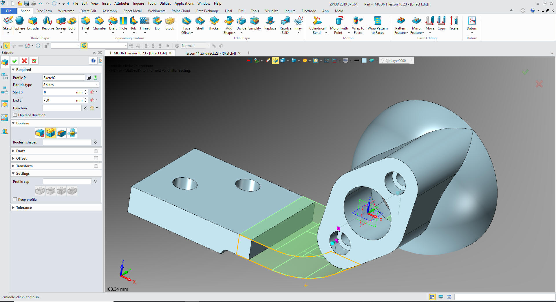
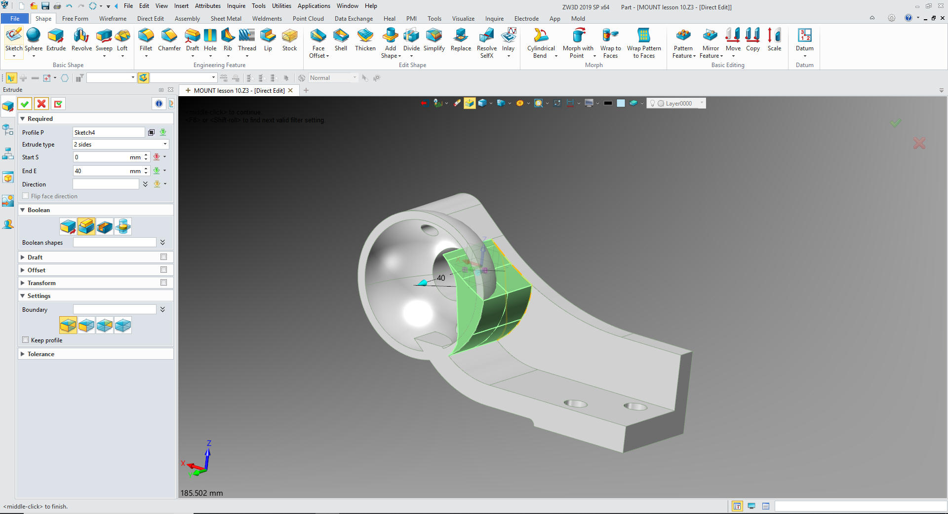
We exit the sketch and extrude the profile and set to remove.
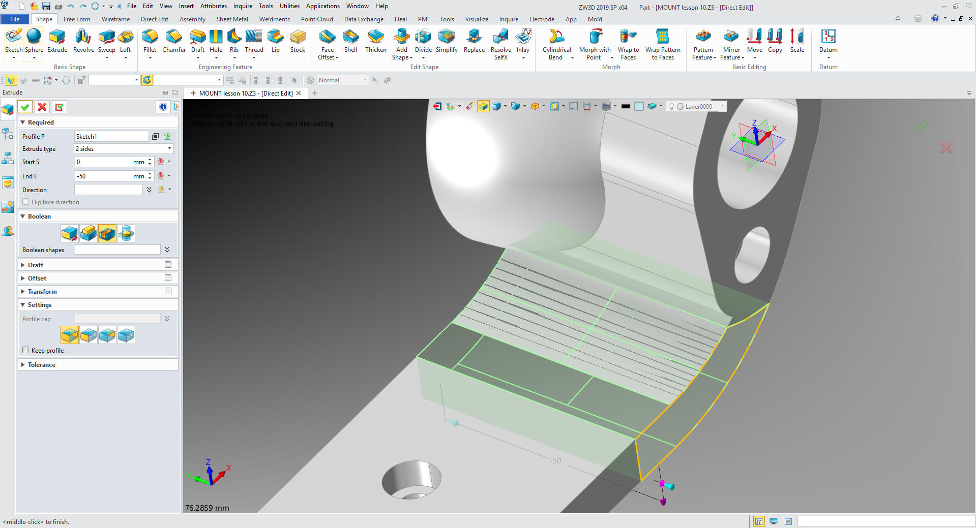
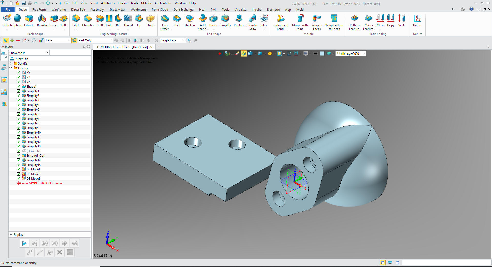
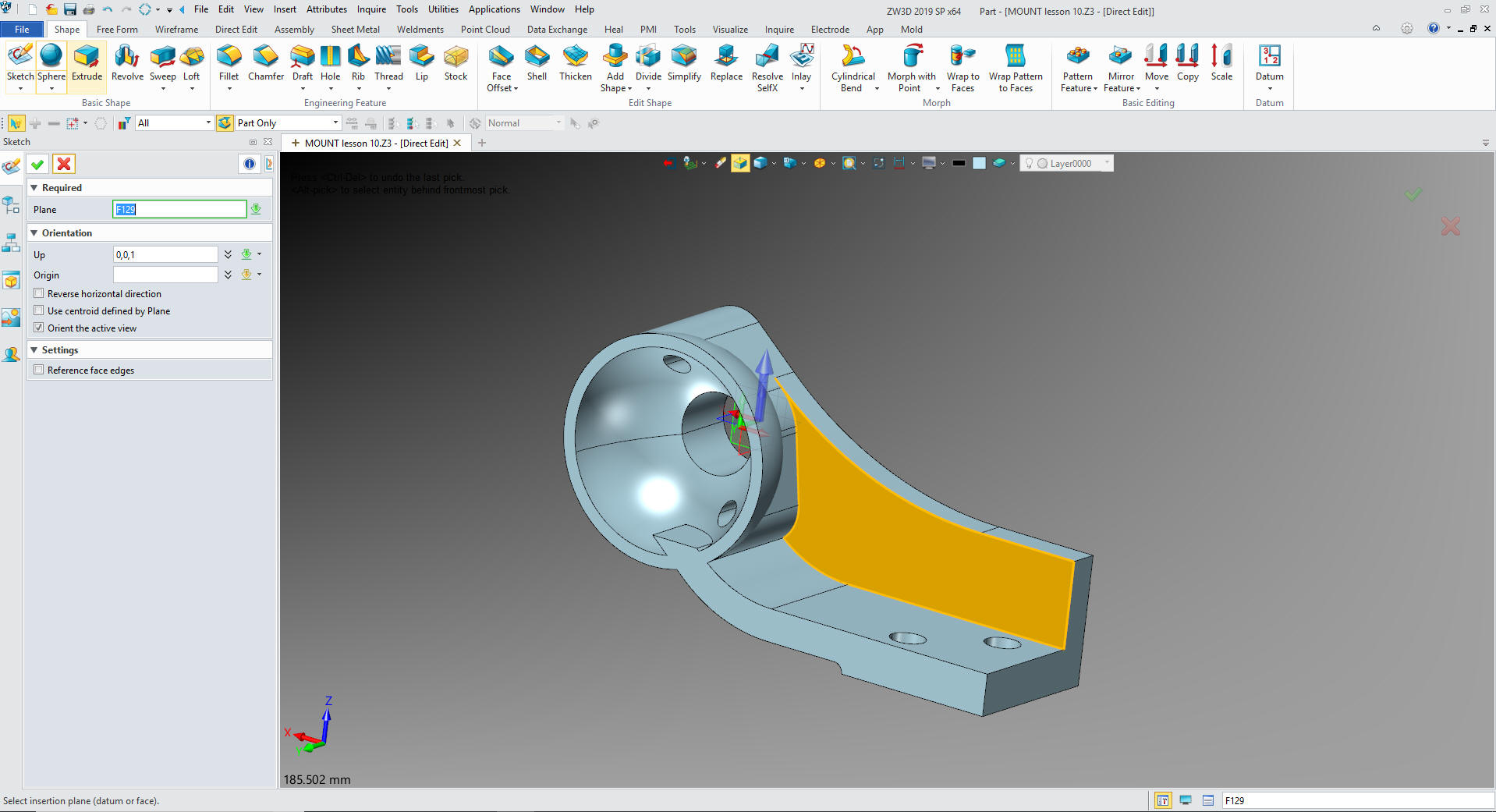
Now we just simplify the faces.
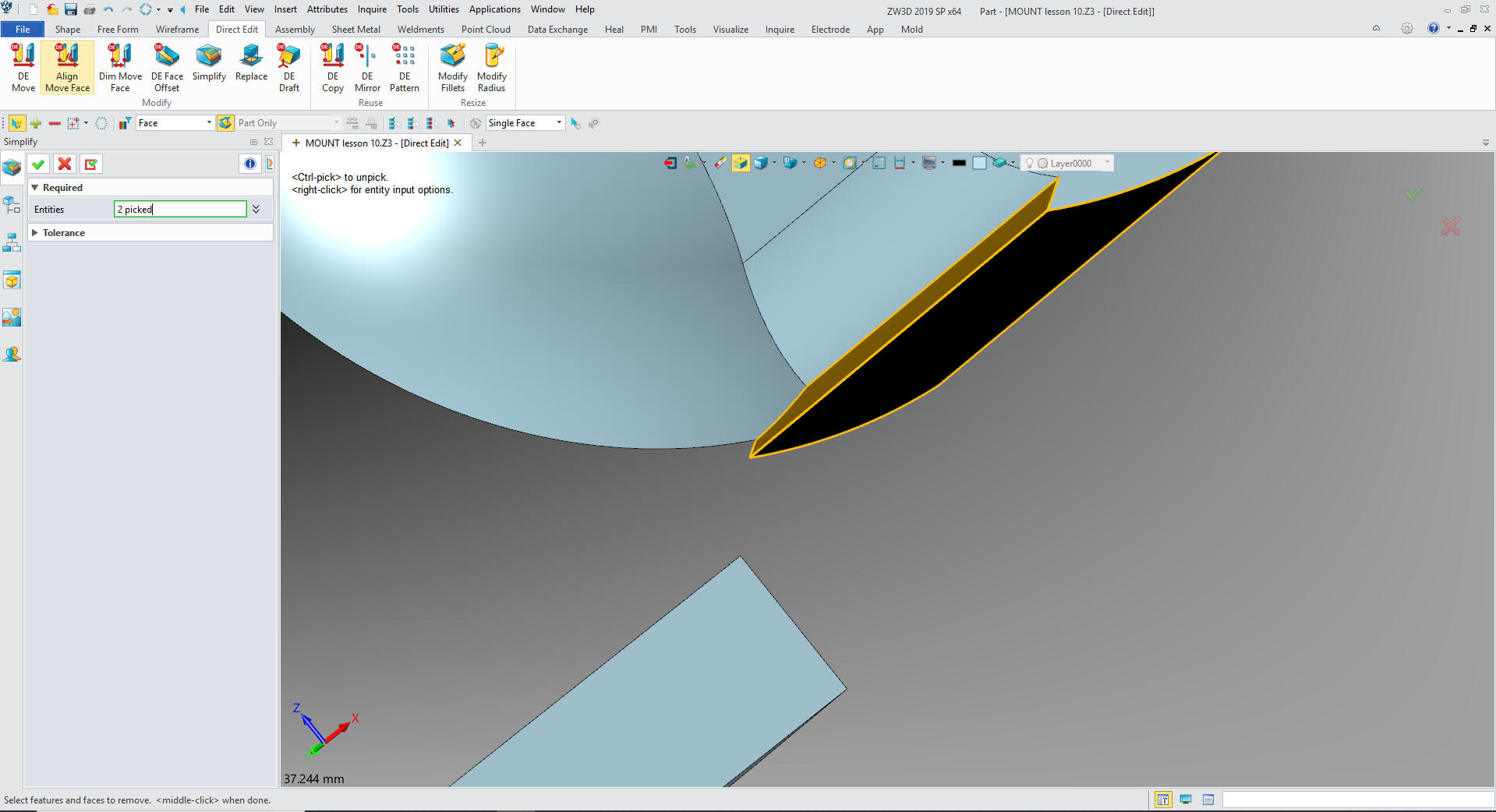
Nice
and clean.

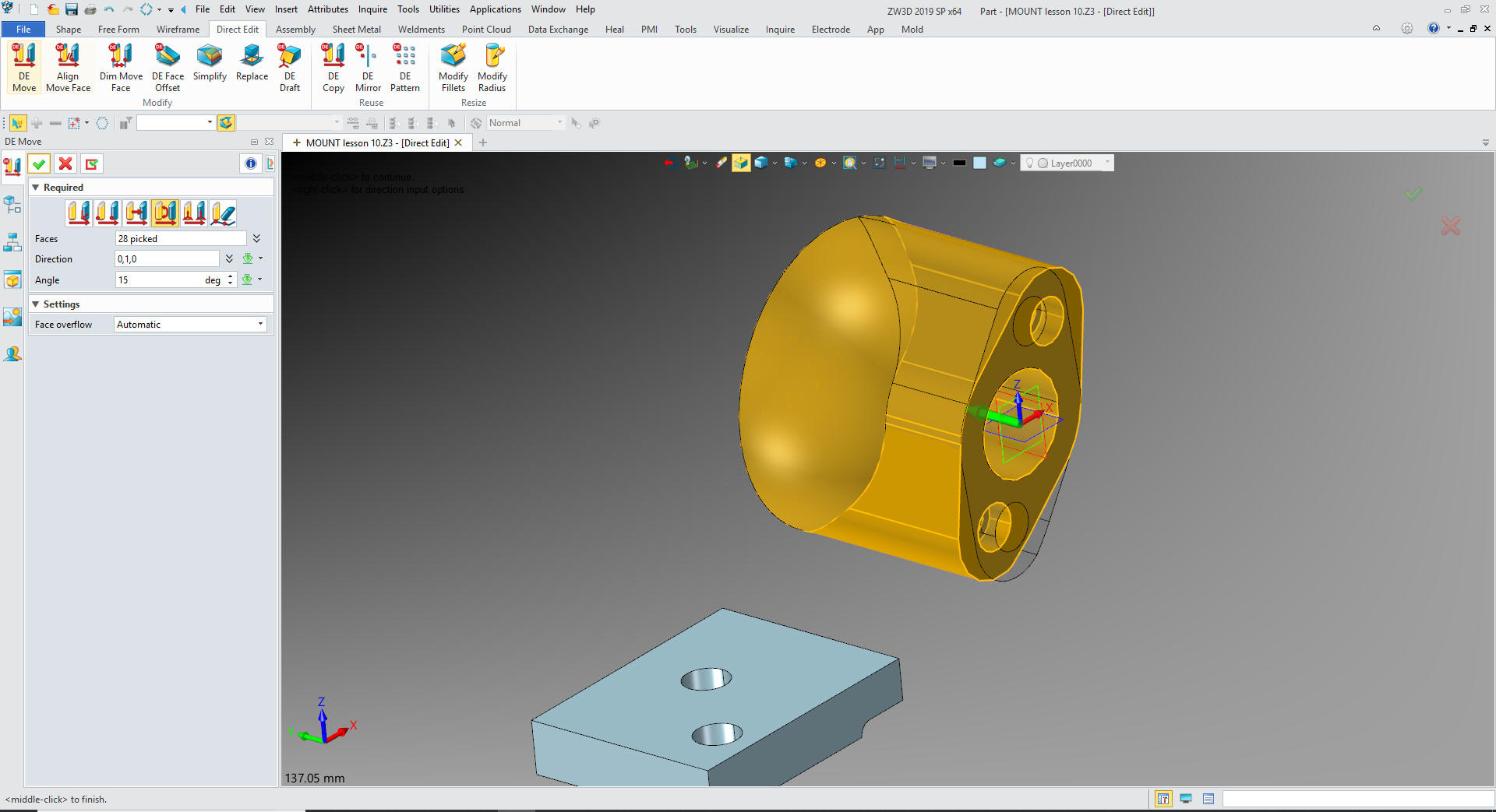
Now
we rotate the feature.
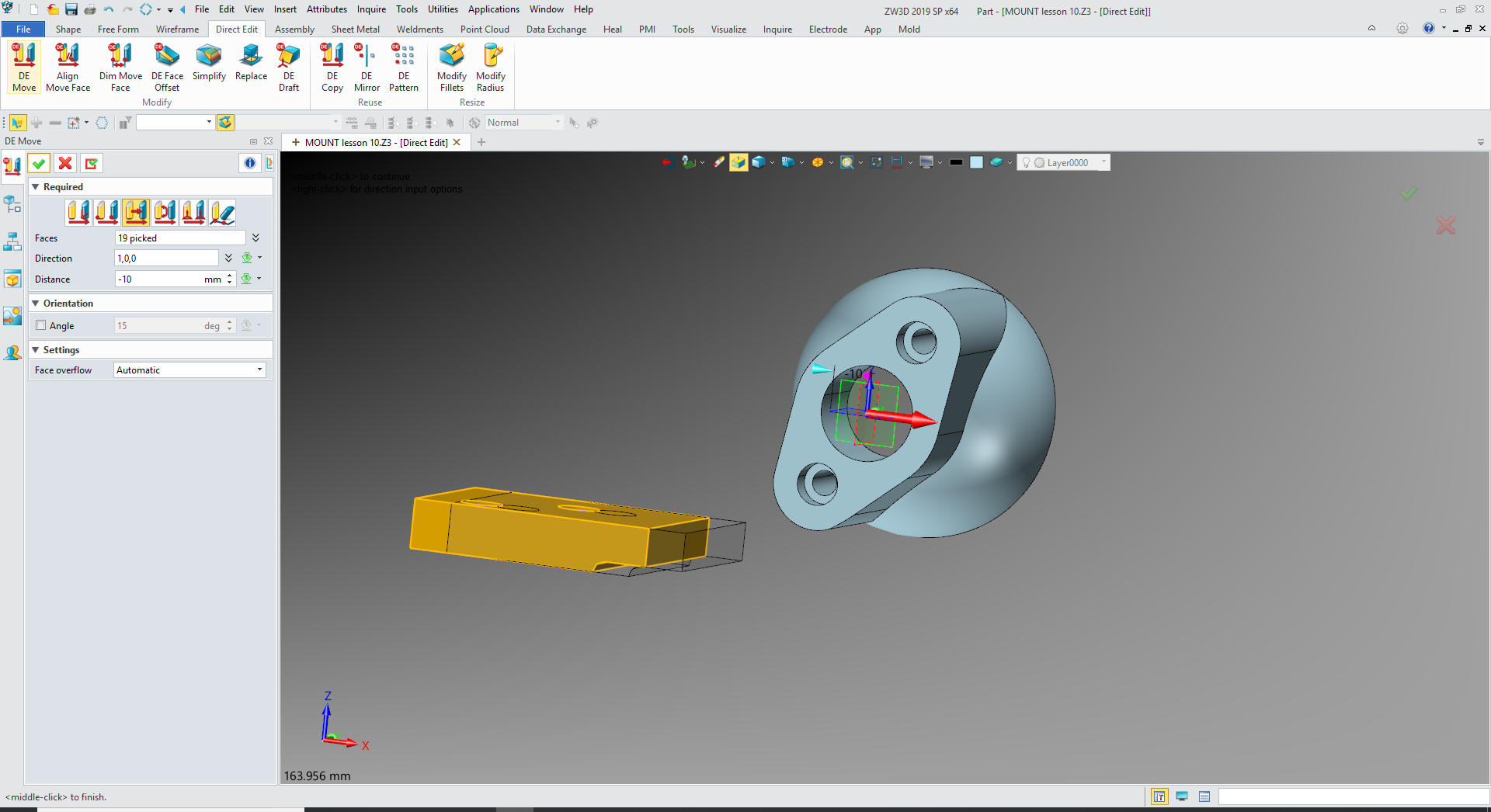
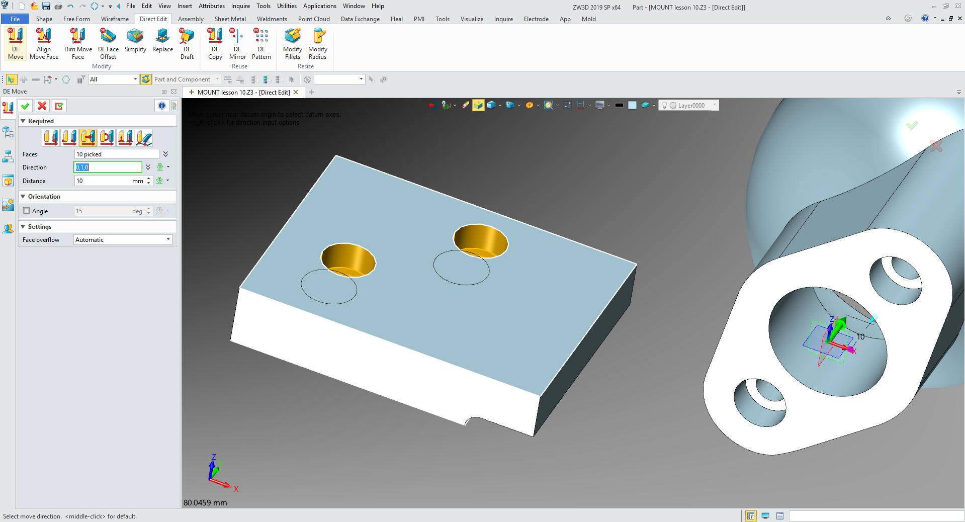
Now
we can also move the base 10mm
Now
to relocate the holes.
Now
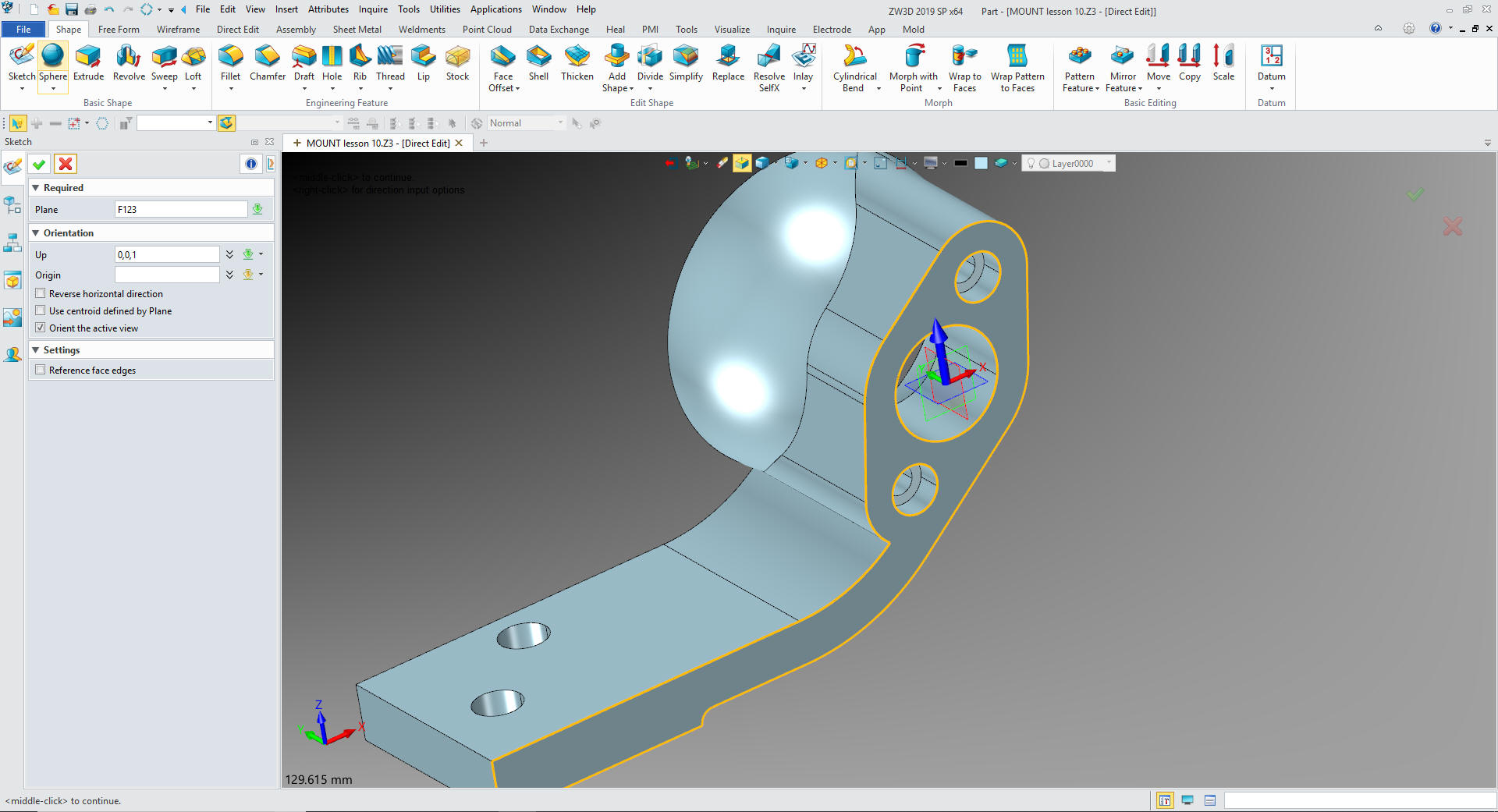
we just create our sketch to connect the base.
We
define the sketch
We
exit the sketch and extrude add.
Now
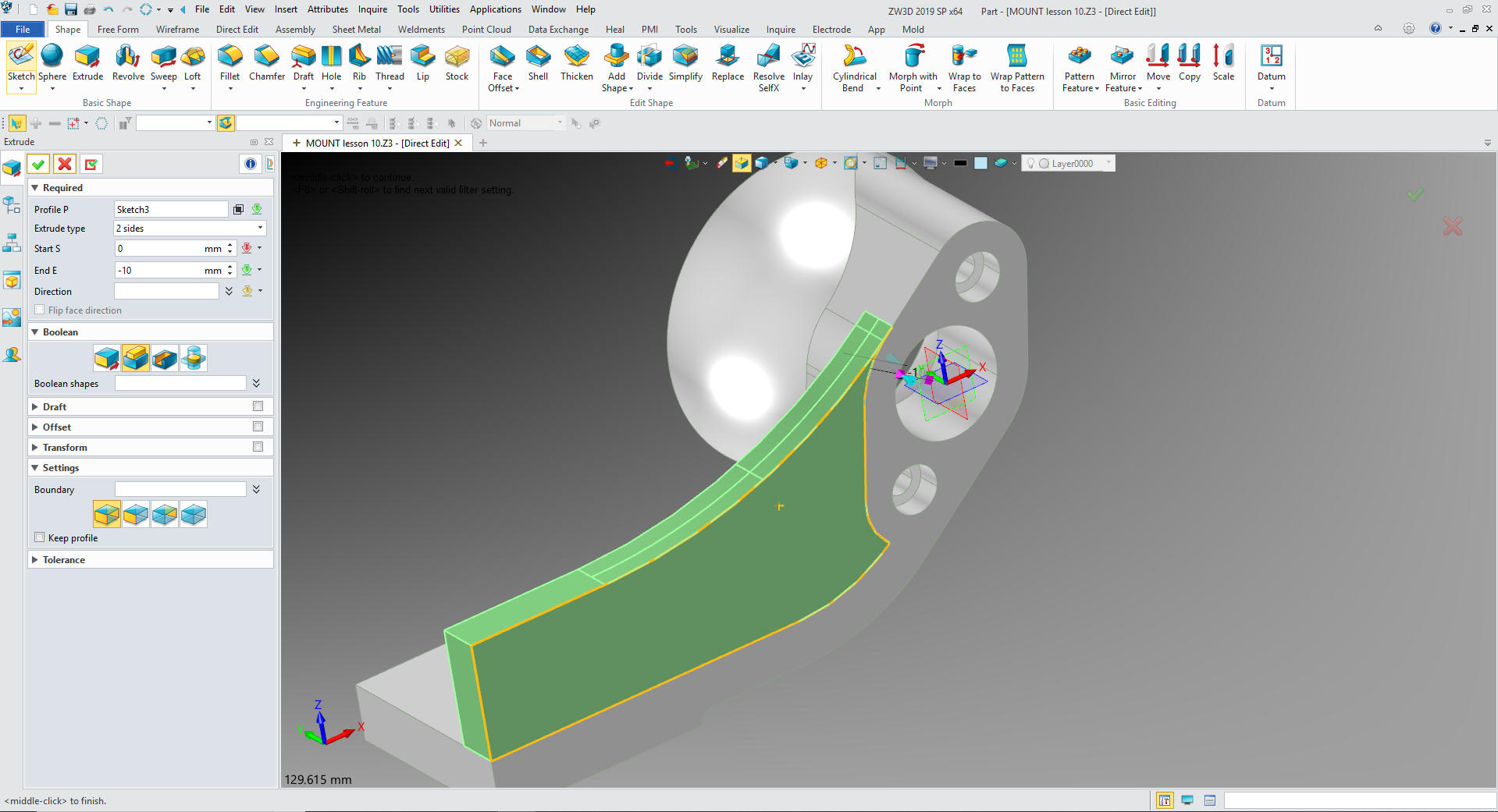
for the front wall. We create another sketch.
We
create the sketch
We
extrude the profile set to add.
Now
for the interior feature. We create the sketch. Yes I see the
extraneous feature in sphere. We will fix that later.
We
create the necessary edges by projecting reference entities.
We
convert the reference entities to working entities and trim/extend.
We extrude the profile and set to add
For
extraneous features we just insert a primitive sphere to the center,
size it and set to remove.
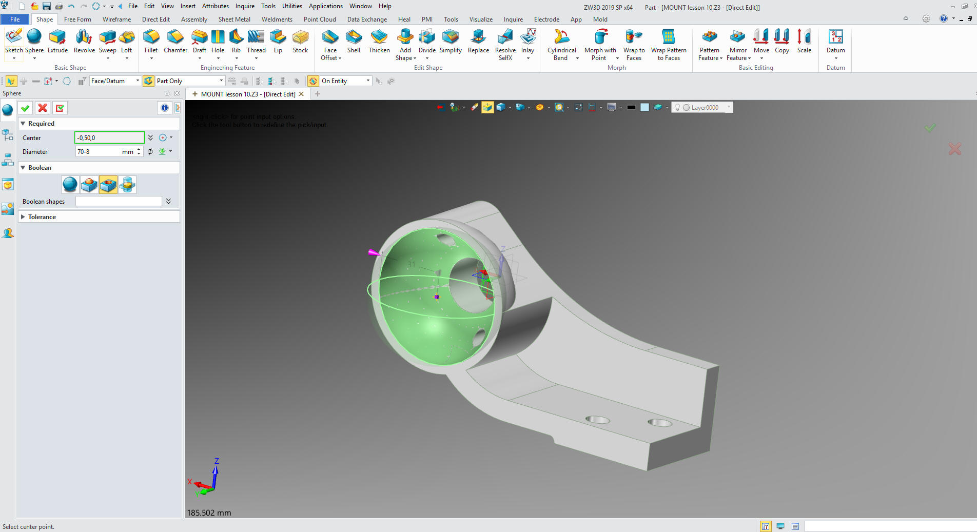
There
you go, a bit of direct edit modifying. We just add the fillets and
we are done.
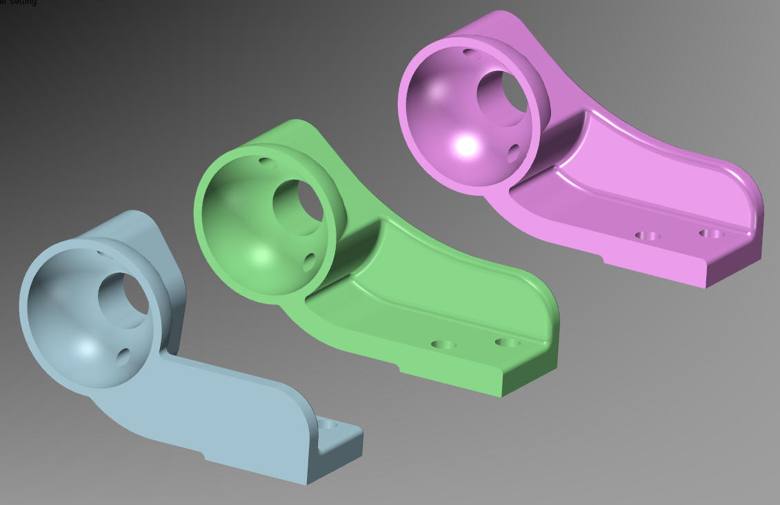
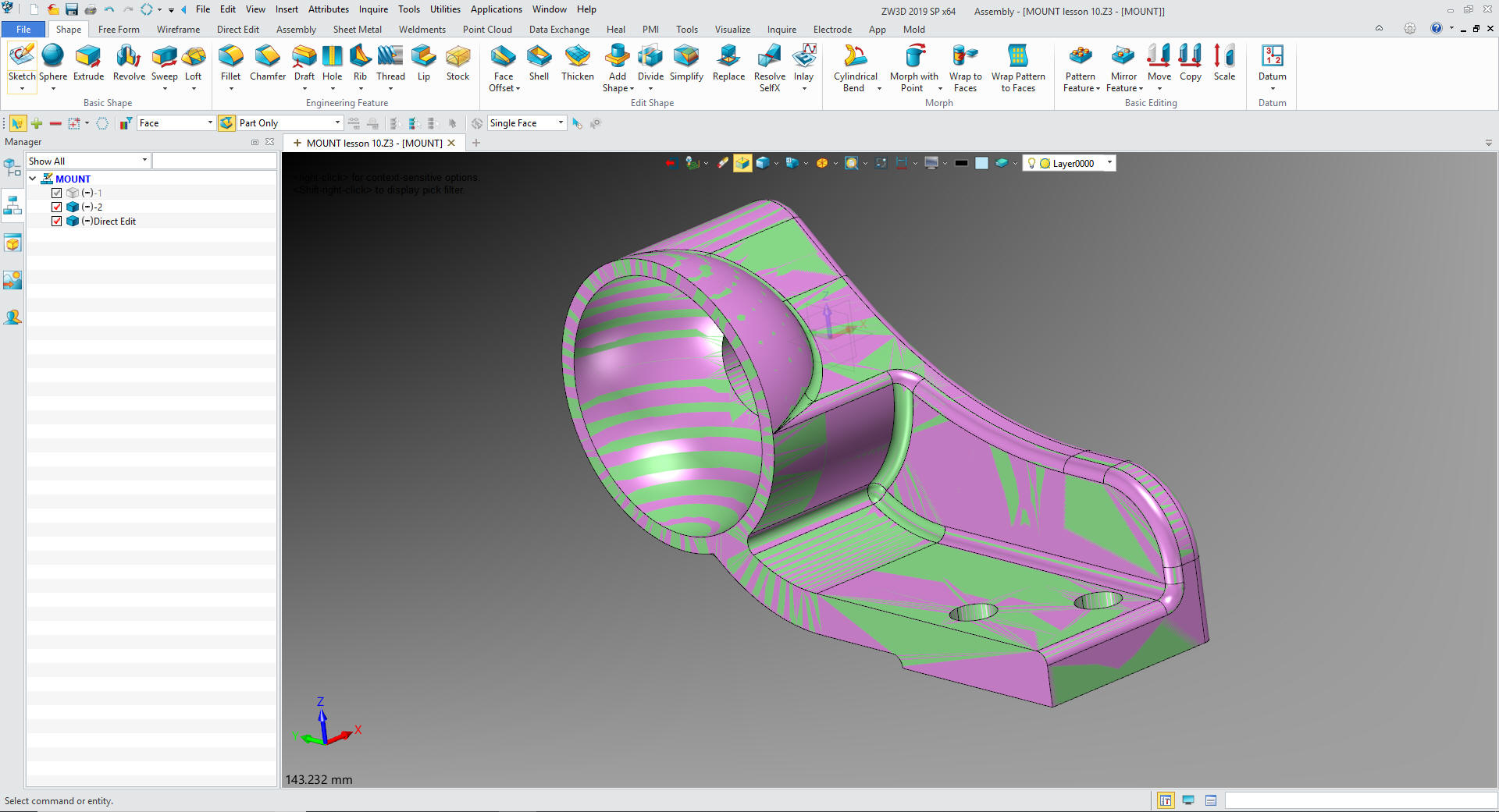
Now
we turn on -2 and direct edit, change the colors and you can
see they are identical! I had my doubts on the robustness of ZW3D
with direct editing but this exercise put them to rest. It was a lot
of fun!
Time
for the AIDS. ZW3D is the only history based system with a
multi-object modeling system with integrated AIDs. Imagine the PDM
Problems this would solve.
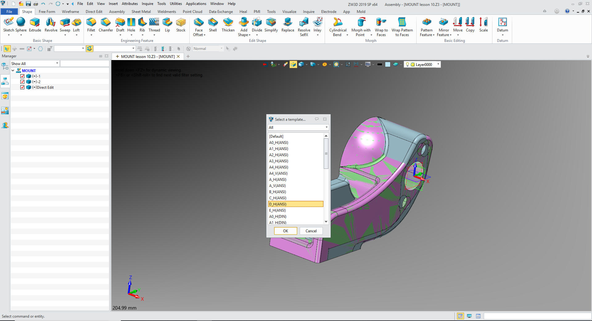
While in the assembly I created these
sheets with a
right mouse click and selecting 2D Sheet so I would have the two
sheets in one document. I will not go into the detailing process,
but it is a relatively easy robust documentation system.
I
just select -1 and set up and detail the AID.
Then
we add a new sheet and select -2 set up the sheet and detail the
AID.
Please review other exercises.
ZW3D vs Solidworks
ZW3D vs Fusion 360
ZW3D vs Creo
ZW3D vs NX
ZW3D vs CATIA
ZW3D vs Inventor
ZW3D vs Solid Edge
You
can see more on modeling techniques here.
3D Modeling Techniques Defined
If you would like
to try ZW3D please download for a 30 day evaluation.