3D Modeling Techniques ZW3D vs Solidworks Lesson
Eleven Streamlined Sketching/Feature
Based Modeling Two Similar Parts and AIDs:
Single File
I saw some Fusion 360 exercises online and I decided to compare
ZW3D. It quickly turned into a study in modeling techniques. I have created
many comparisons to Fusion 360, Onshape, Solid Edge, NX, Creo,
Catia and Inventor
lessons to show the difference
between ZW3D and my modeling techniques. I found the presenters working
identically wasting massive amounts of time
with overly complex constrained sketching procedures. I was so unimpressed that
I decided to model the parts or assemblies showing my modeling techniques plus 's superb design system.
3D Modeling Techniques Defined
Many of these modeling techniques can easily be implemented even
within their existing system. I call it Streamlined Sketching and
Feature Based Modeling. Please review a few of the above ZW3D
comparison lessons, there are some very stark differences.
While creating 3D models from drawing is the very best
way to learn 3D CAD and maybe some design techniques it does not
expose the designer to the design flexibility necessary in design.
ZW3D is all top down due to the multi-object model environment.
Creating mating parts is a cruise. But modeling is just one aspect of a
well designed productive 3D CAD system.
Solidworks
is a marginal 3D CAD system based on the dated Pro/e (Creo) history
based modeling system. I have sold this product years ago and found
it, like all of the other Solidworks clones, not productive enough
for our engineering department. We use what we sell. That gives us
the experience to effectively support our user base.
I would do a
video, but I really am not good at it. So I will show you step by
step. I will try and get ZW3D support to create one. They are
very good.
The modeling technique is hugely responsible for
the level of productivity. Those of you that are only trained in the
constrained sketching world are truly limited by not
using the freedom of feature based design, that is available in even
the most Solidworks-ish of CAD systems. If your
designers are designing in these very unproductive and time
consuming processes it might be time to review your standard design
processes. Don't have any do you?
These lessons have actually turned into exercises in
modeling techniques as compared to showing a more productive CAD
systems. Again, I say, there are many different ways to model a part.
I see with my exposure to direct edit modelers like CADKEY, I
rarely sketch like you see the Solidworks fellow doing. I have always
created my basic sketches by mostly creating offsets and extending
and trimming or. It seems to be much easier. I never put in a fillet that
can be created later. What do you think?
Let's get started!
You will see
with Streamlined Sketching and Feature Based modeling is much more
productive and flexible. It gives you a more real world feel to
your design process and is a much more pleasurable and productive experience.
Modeling Technique Note:
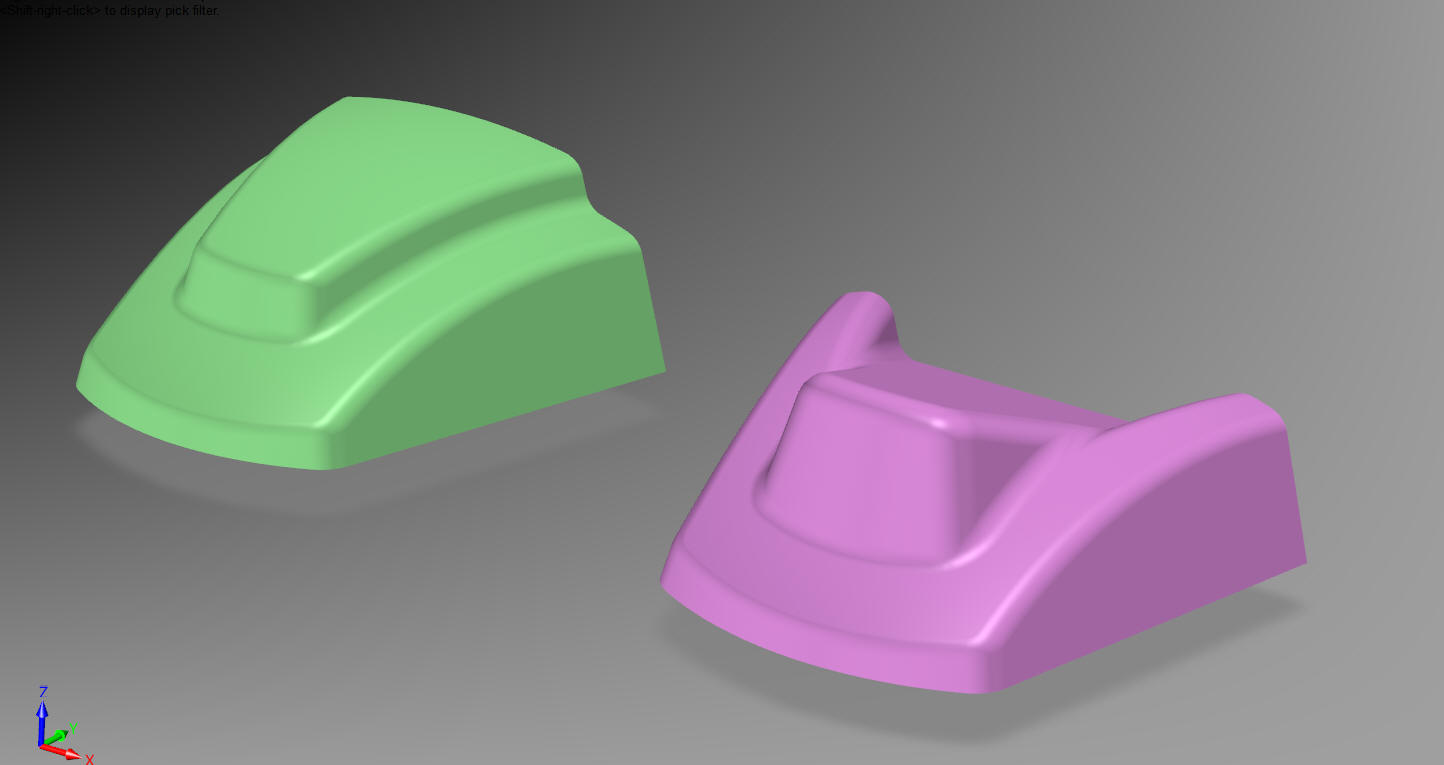
There are two similar parts. In
IronCAD we have a single model environment, ZW3D offers a
Multi-Object environment. As I started these parts I realized I
would have two parts to define. So I will start with an assembly
that include the two parts. I am wondering it this would also be a
viable solution for the Solidworks clones, unless they are already
doing it.
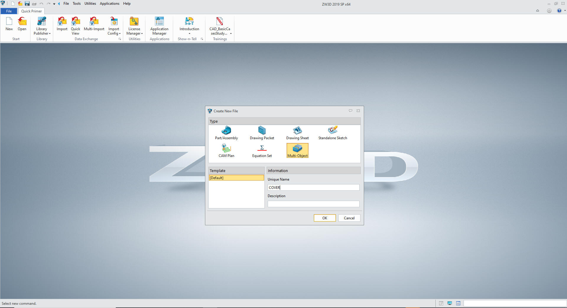
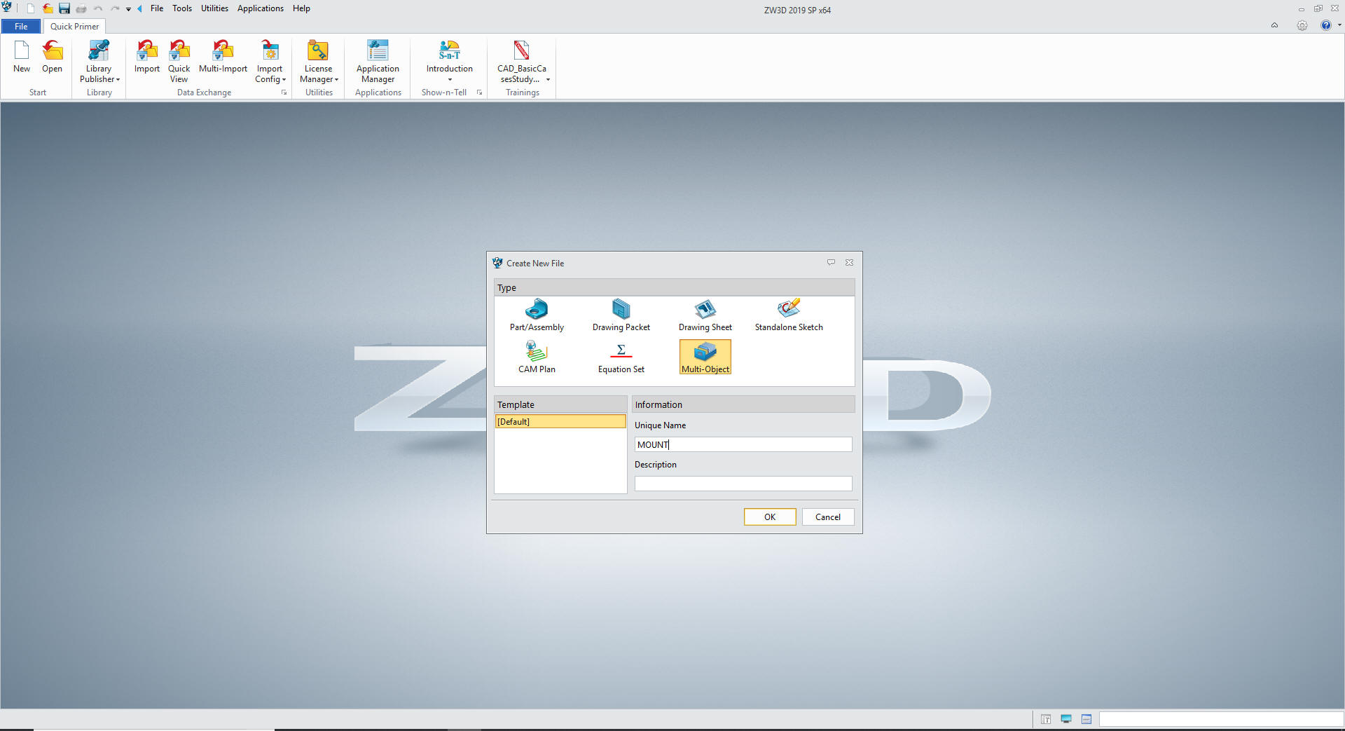
We will set ZW3D to millimeters!
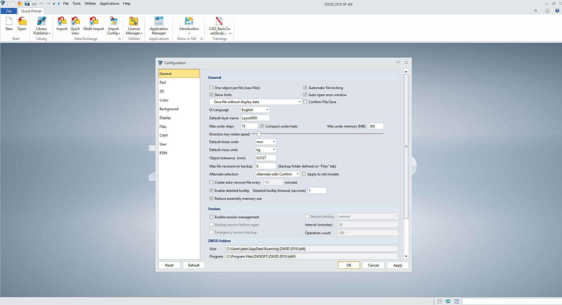
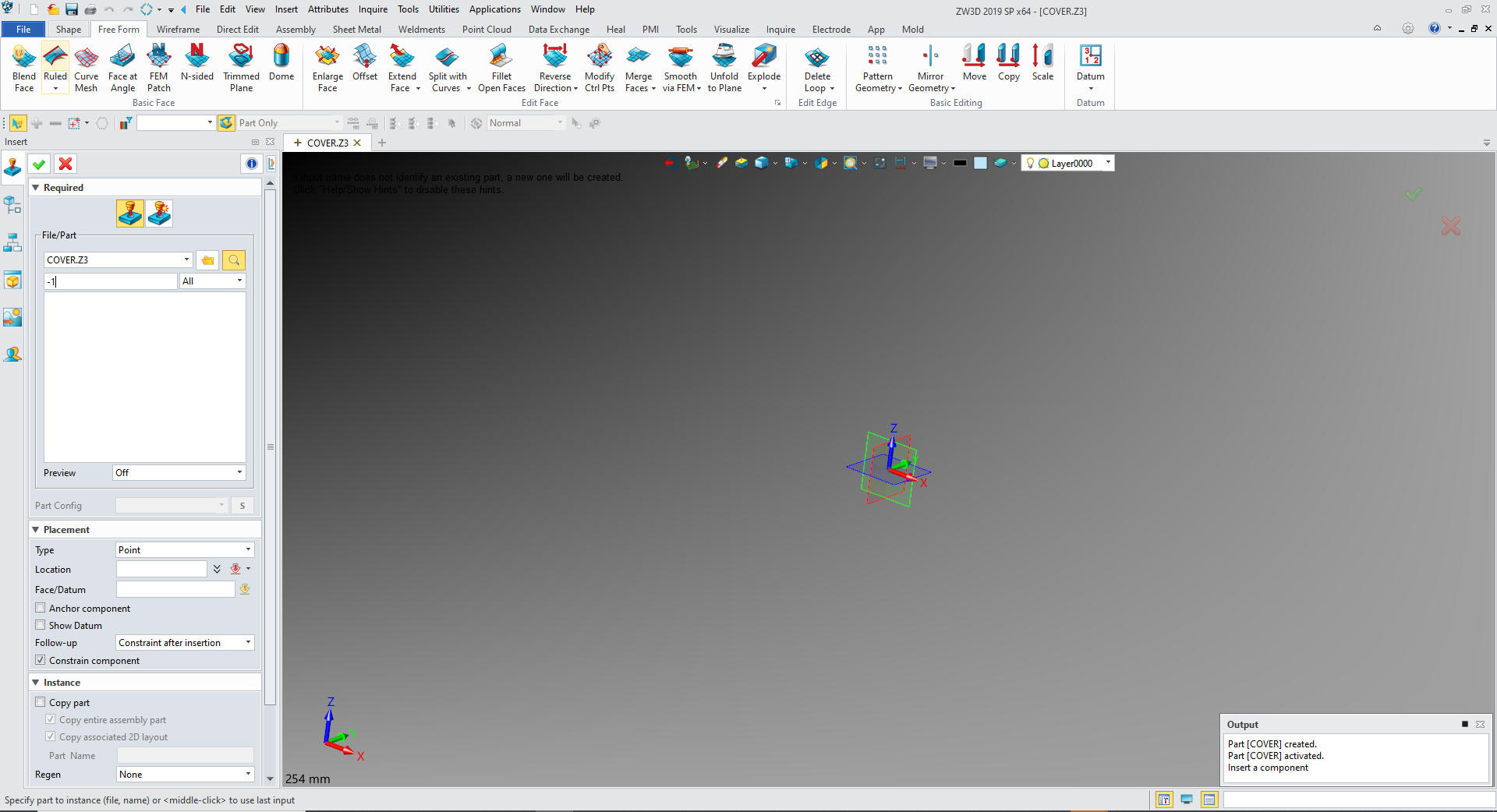
So we
open an new file by selecting a Multi-Object file type and name it
MOUNT.
We
will open a part and name it COVER. This will serve the purpose
as the top file.
Under
COVER we will insert a component -1
We can
now start creating -1. We will insert -2 later when we are done with
-1
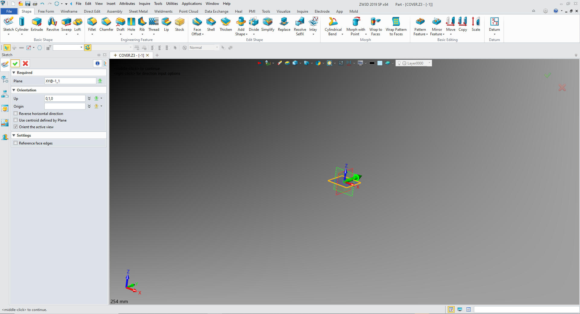
Many time we start our modeling with a primitive shape,
but we will start with a sketch on this part.
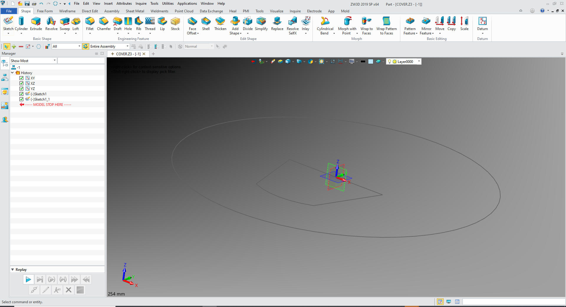
We create a
sketch on the XY plane
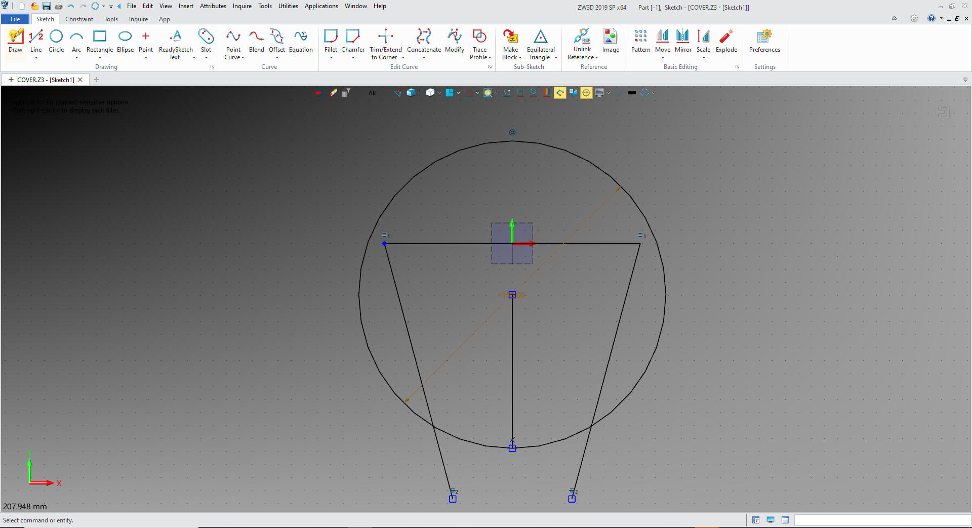
We
create our sketch. ZW3D allows you to put the entities in and define
them in the same step. I use entities to construct my sketch. Here
is the rough sketch, notice there are no constraints.
Notice
where X0Y0 is, this is important in the creation of the sketch.
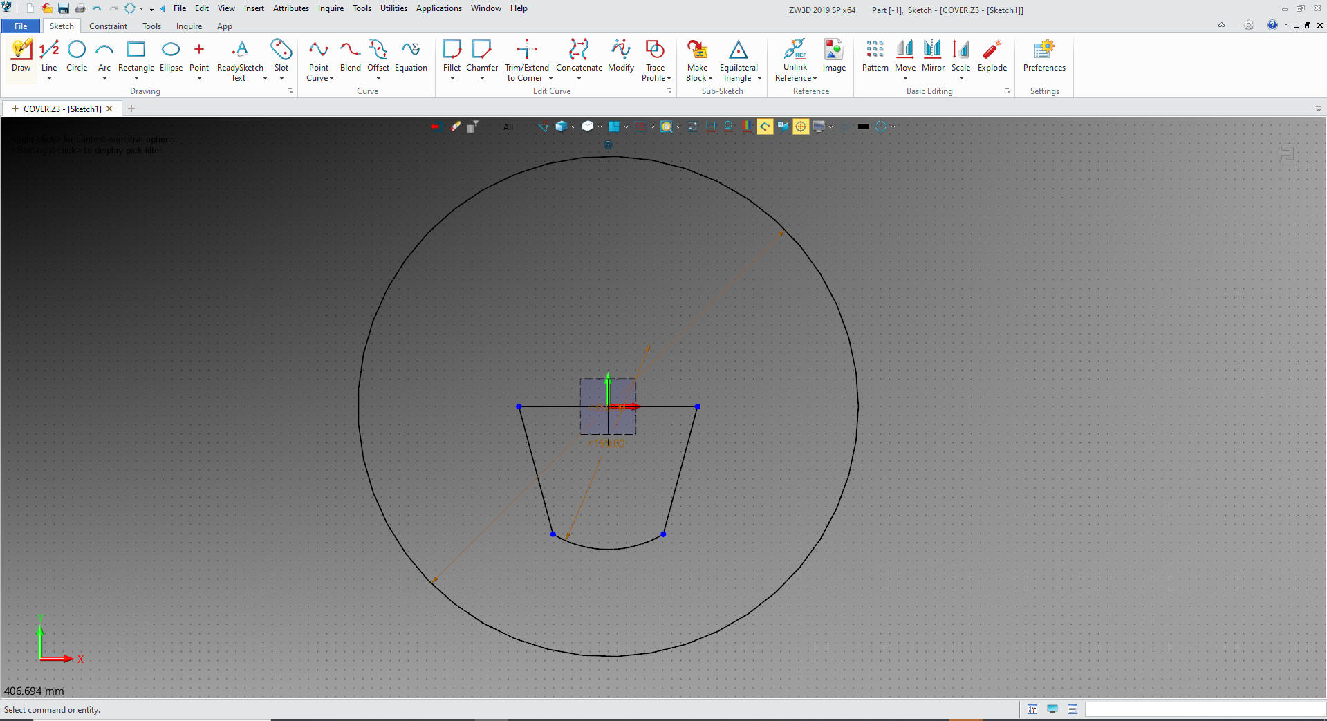
I
clean up the sketch and add a 350mm diameter circle.
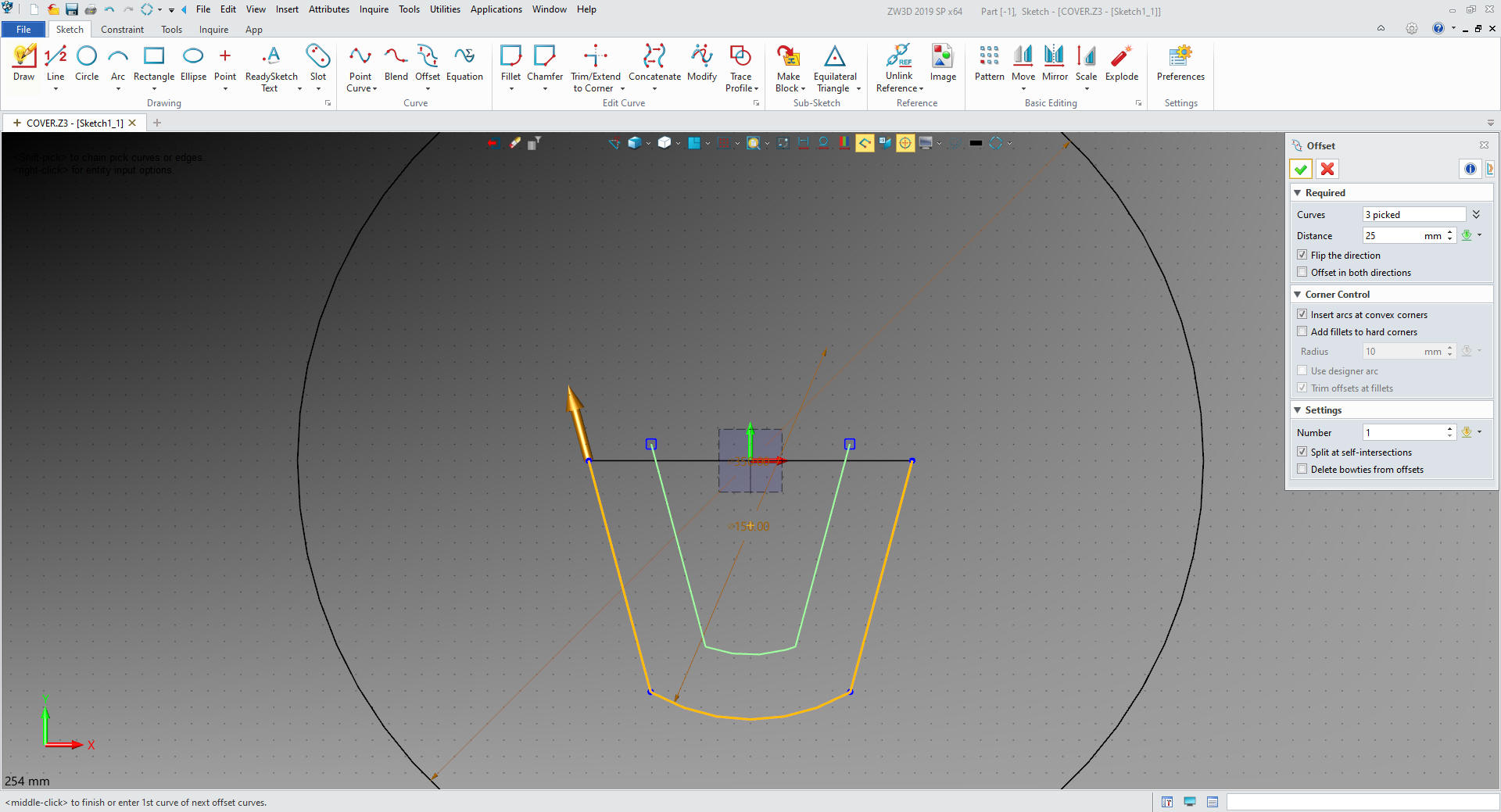
I exit the sketch,
the part is made up of two sketches the second made from the first.
So I copy and paste the sketch.
I
will edit the new sketch by offsetting the entities. I will trim
these up and exit the sketch
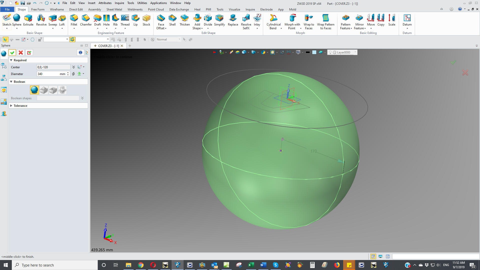
We insert a primitive sphere locate it and
size it 340mm
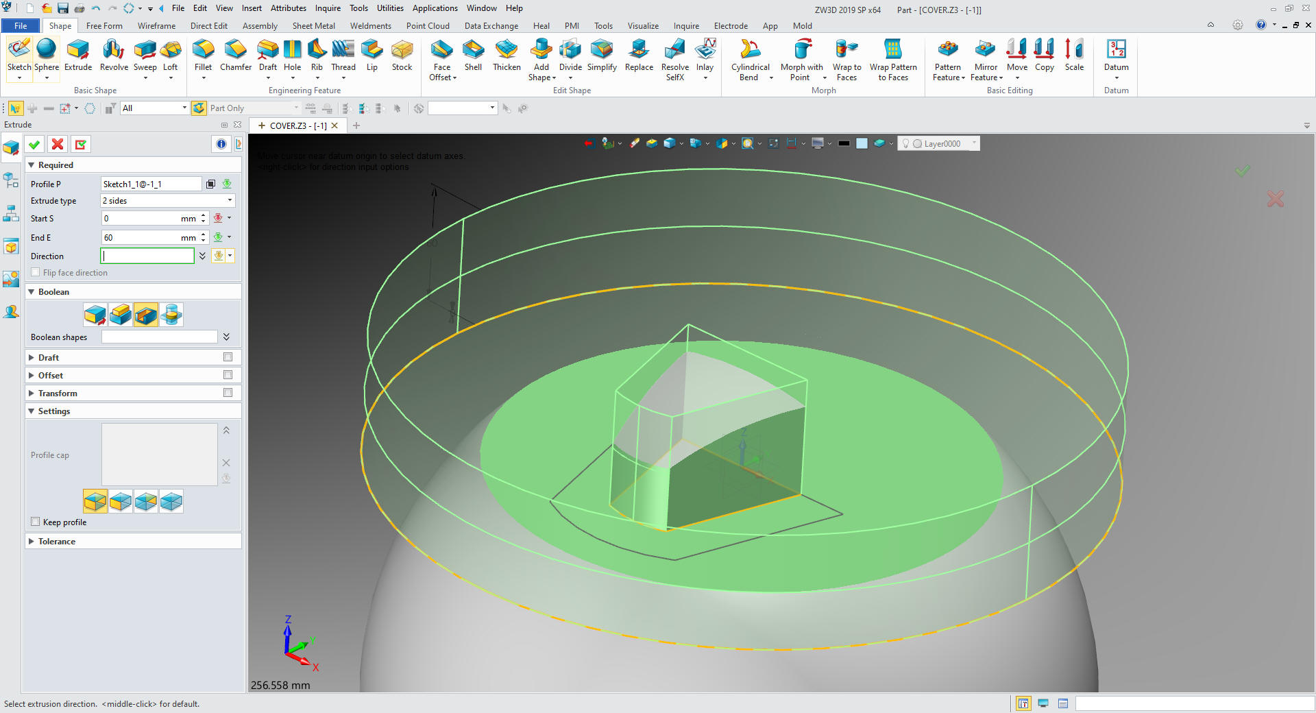
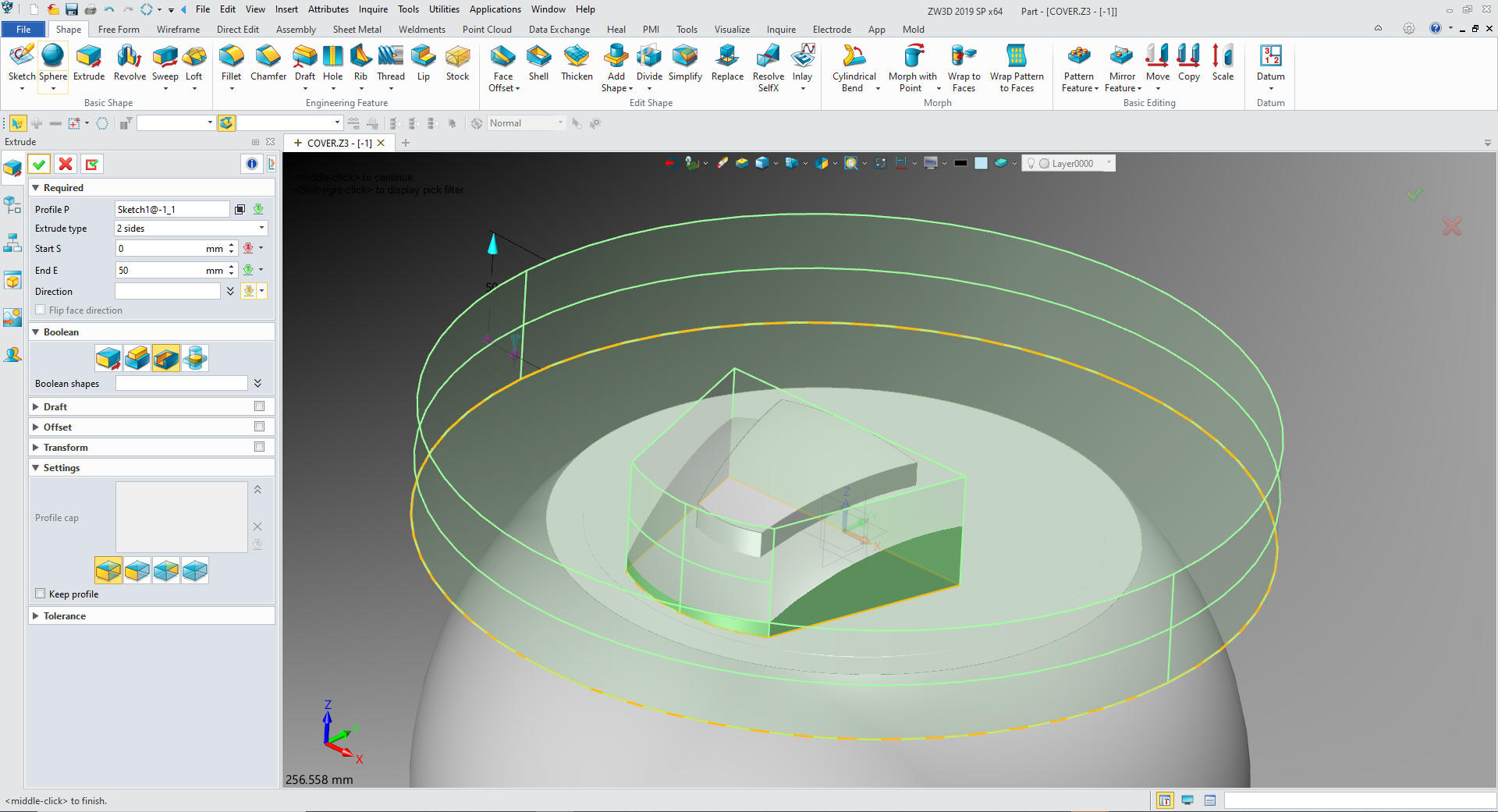
Now we extrude the 2d sketch. We have the upper part of our shape.
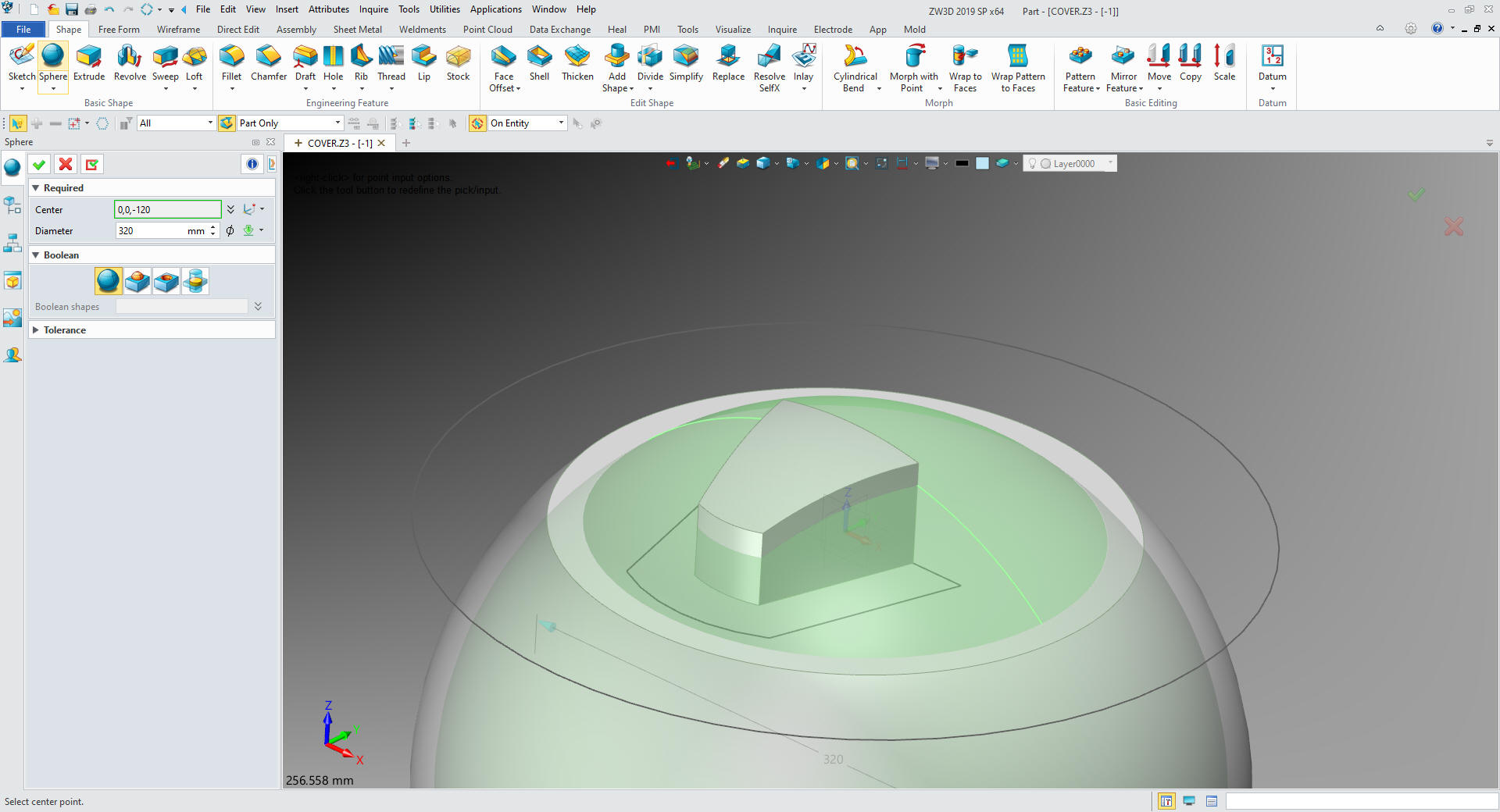
We now
insert a primitive sphere, locate it and size it
to 320mm
We will extrude the first sketch
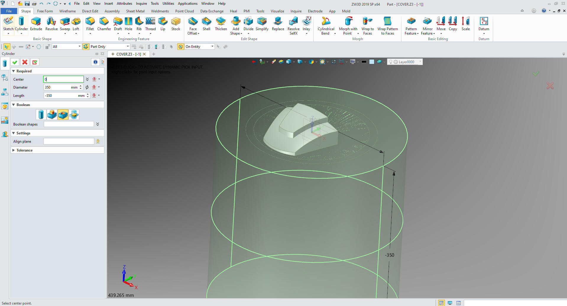
We now insert a primitive cylinder and size it large enough to
consume the larger sphere.
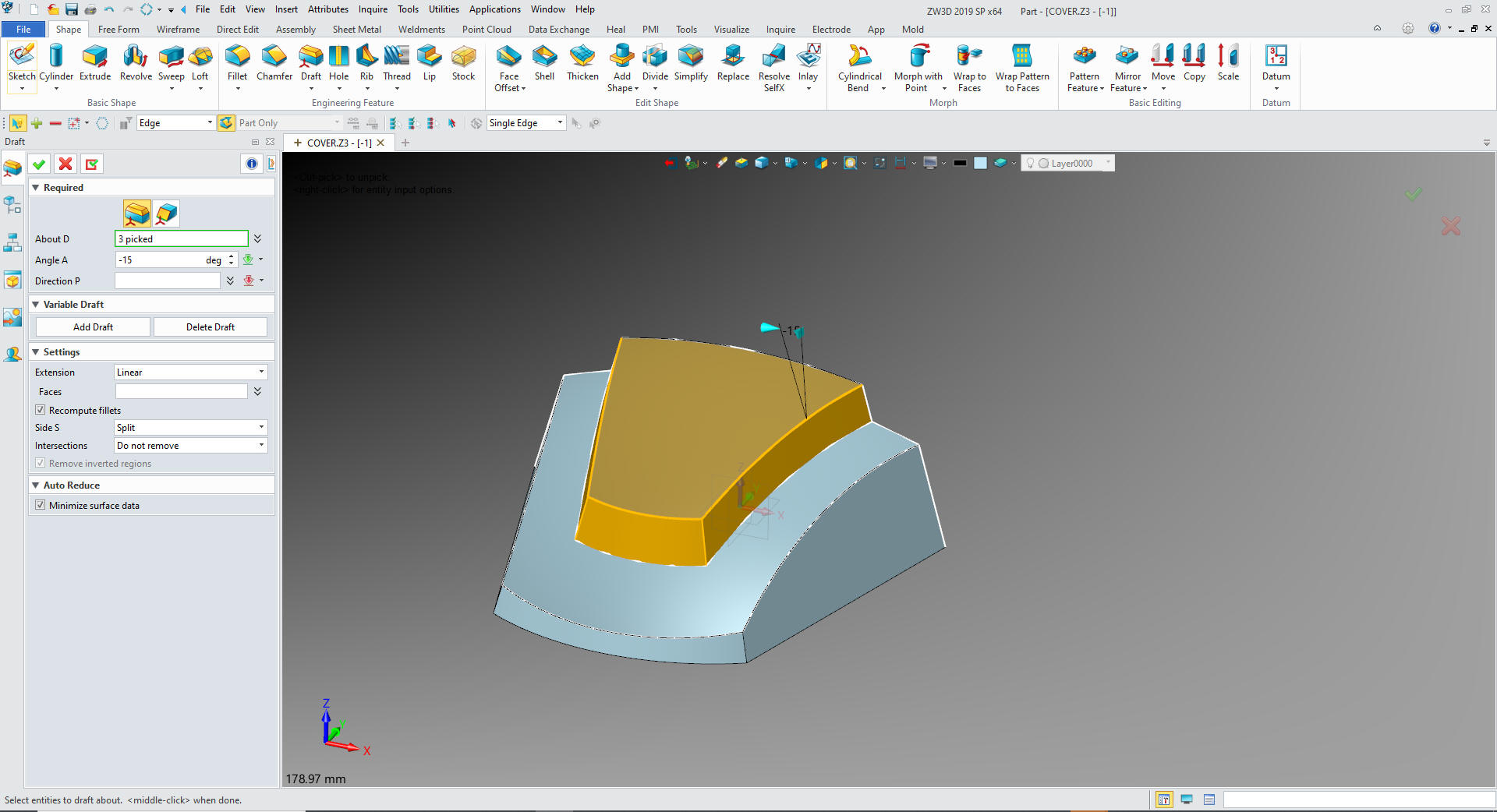
The two shapes have to be combined then we put in the draft.
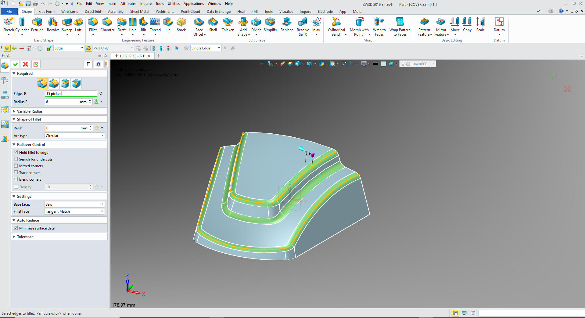
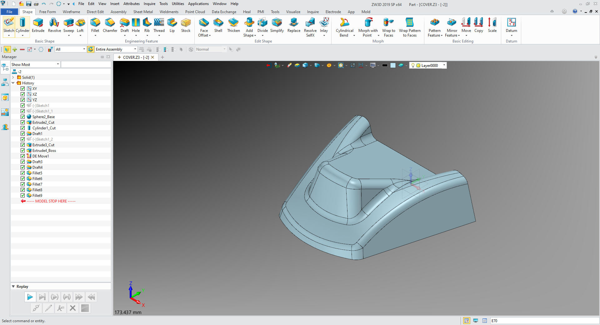
Now for the fillets
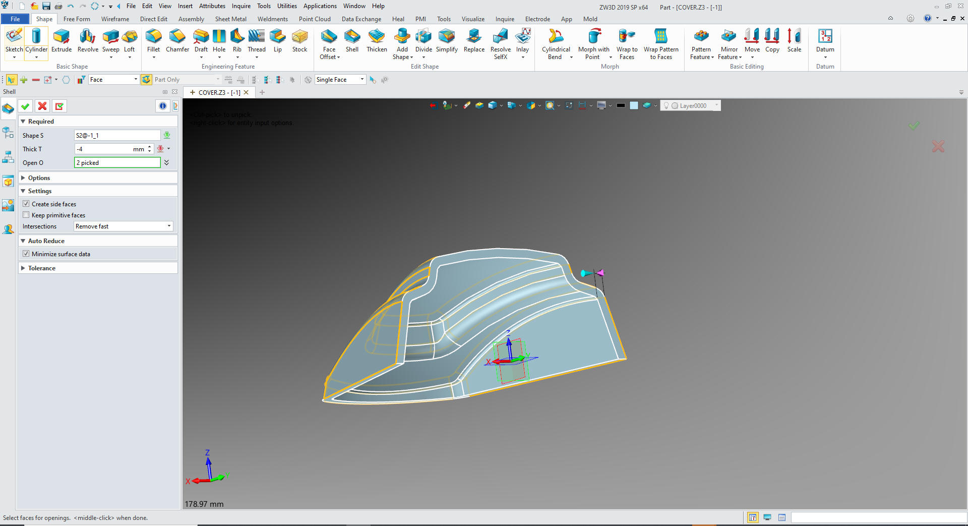
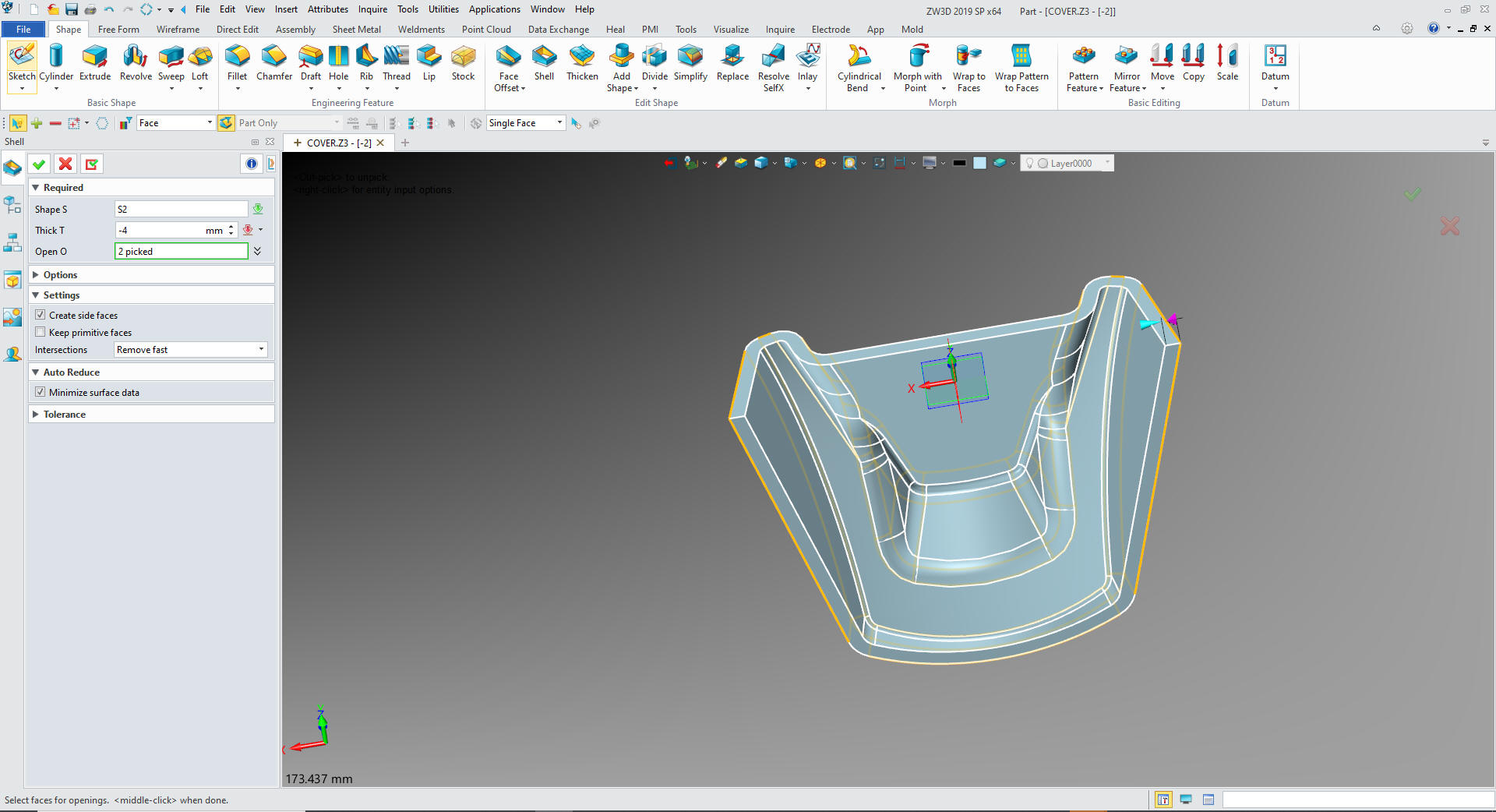
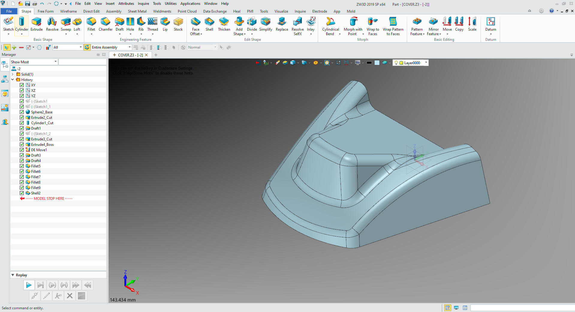
Now for the shell
We are done with the part.
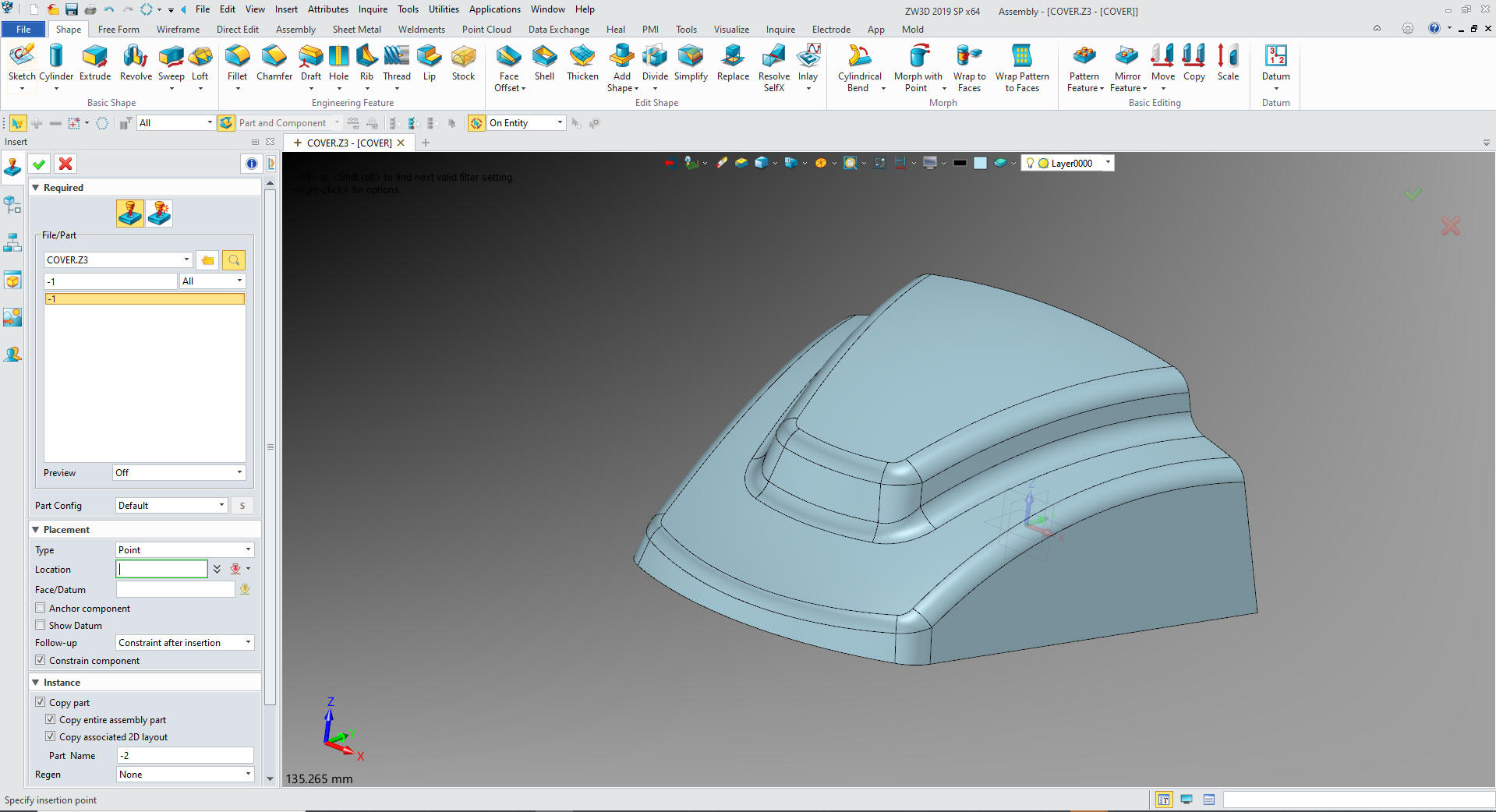
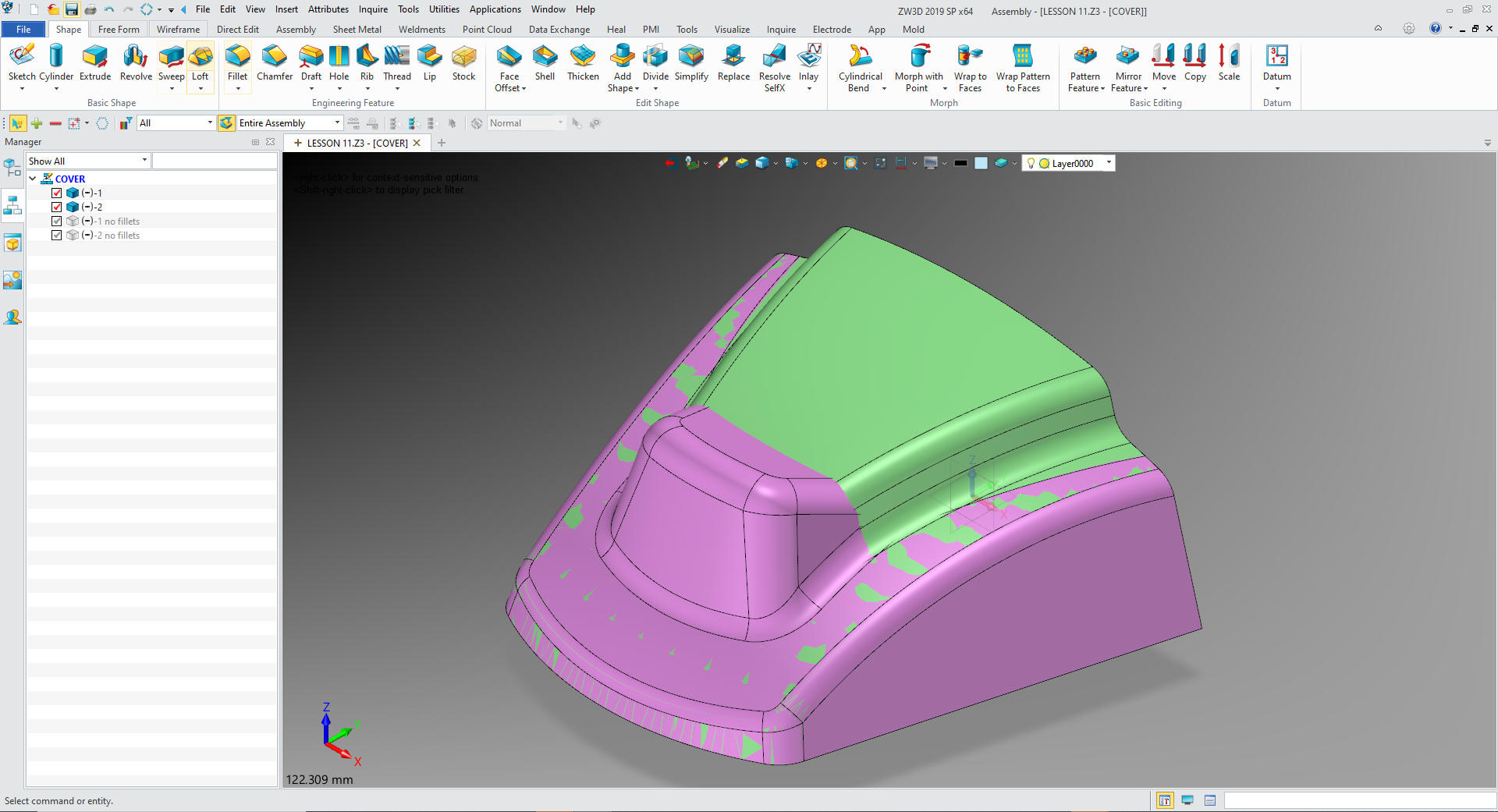
Now
for -2. We will insert a new component under the MOUNT Assembly. We will take the -1 copy it
and name it -2 and locate it to X0Y0Z0
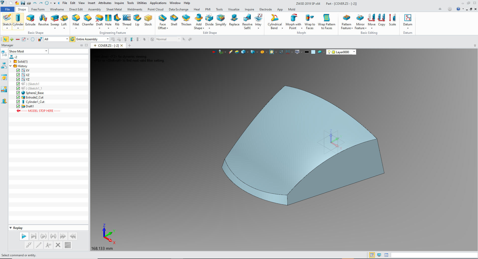
We
open -2 and delete all of the features not required for this design.
We copy the 2nd sketch and edit by deleting the large circle. We
will create an extrusion set it to remove.
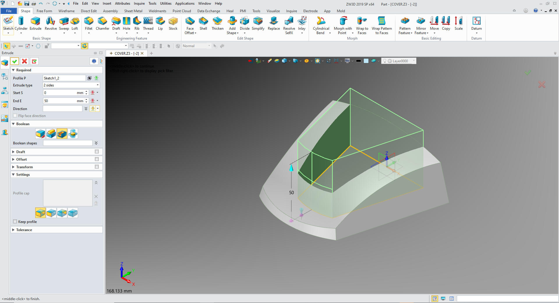
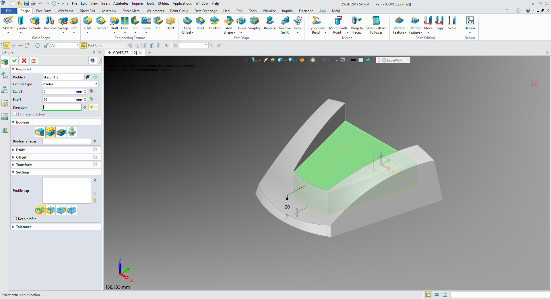
Using
the same sketch we will create a 20 extrusion and set it to add.
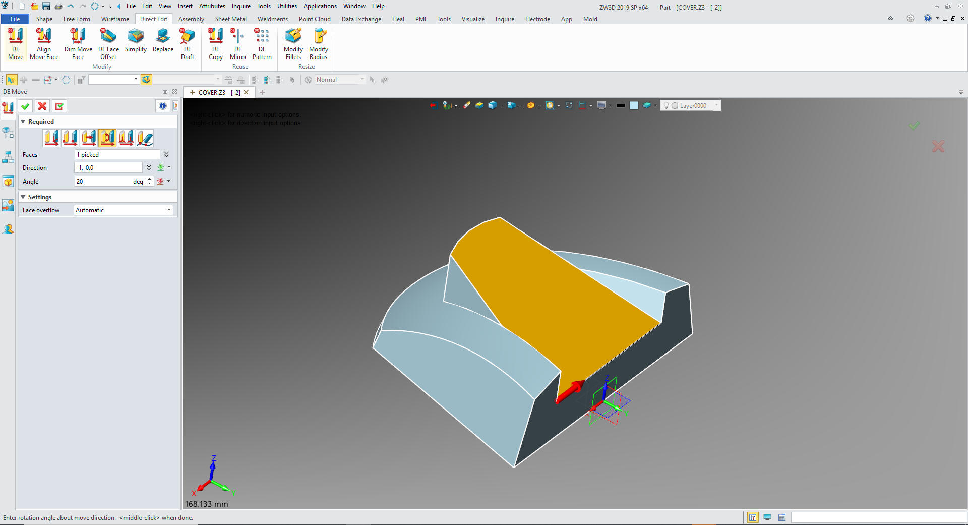
We
will now go to the Direct Edit menu and select face move and rotate
it 20 degees. It not only rotates it but is stays in same
orientation.
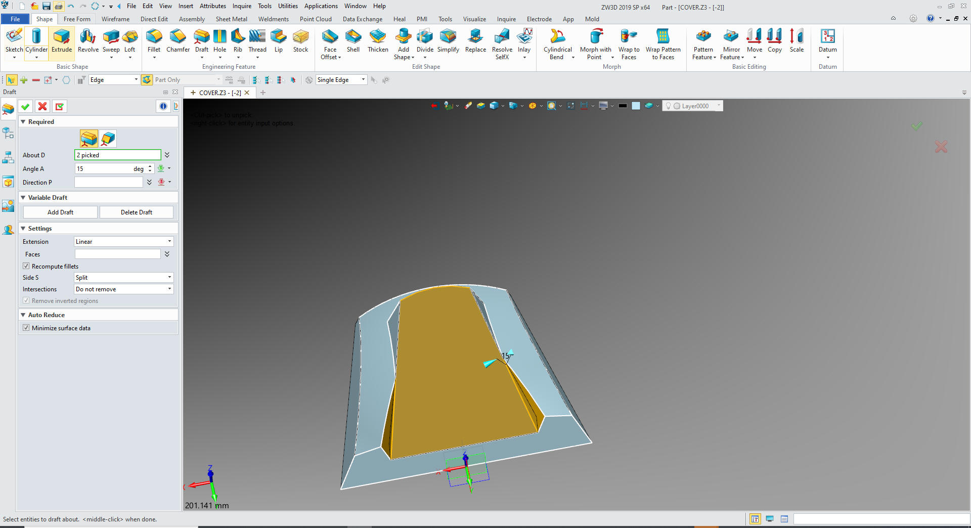
Now
we draft the faces.
Now
for the fillets.
We
shell the shape.
One
more sketch. Selecting the inside face select Y as up.
Time
for the AIDS. ZW3D is the only history based system with a
multi-object modeling system with integrated AIDs. Imagine the PDM
Problems this would solve.
While in the assembly I created these
sheets with a
right mouse click and selecting 2D Sheet so I would have the two
sheets in one document. I will not go into the detailing process,
but it is a relatively easy robust documentation system.
Now we are ready for the AIDs (drawings)
When you create a 3D model from a drawing you
have to do a detailed AID to assure you
have duplicated the drawing. You should also have someone check it
if it is in a production environment.
Give me a call if you have any
questions. I can set up a skype or go to meeting to show this part
or answer any of your questions on the operation of ZW3D. It
truly is the Ultimate CAD/CAM System.
If you are interested in adding professional
hybrid modeling capabilities or looking for a new solution to
increase your productivity, take some time to download a fully
functional 30 day evaluation and play with these packages. Feel free
to give me a call if you have any questions or would like an on-line
presentation.