|
Jefferson's
Experimental Airplane
Jeff Miller, Engineer and Commercial Pilot, came to me after the original designer, that was using Solidworks gave up. We have been working together on this project. I will keep all posted on the progress!
3-24-19
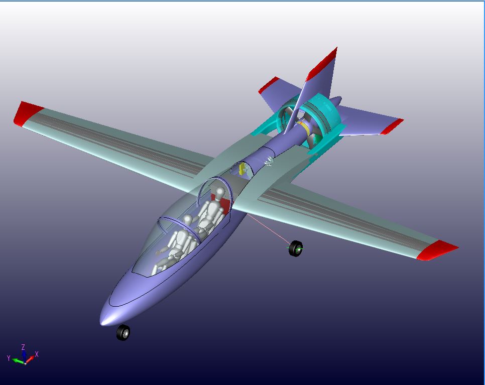
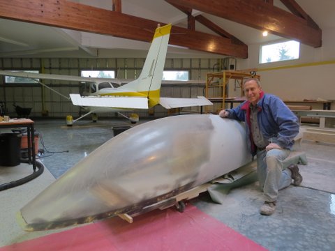
Here is a bit of a status report. Jeff's dream is now becoming a reality, from CAD to tooling! Jeff's house is in a community built around a small landing strip. His house is built around a hanger! LOL.
I am patiently waiting to help Jeff with the design of the structure, controls, instrumentation, etc.
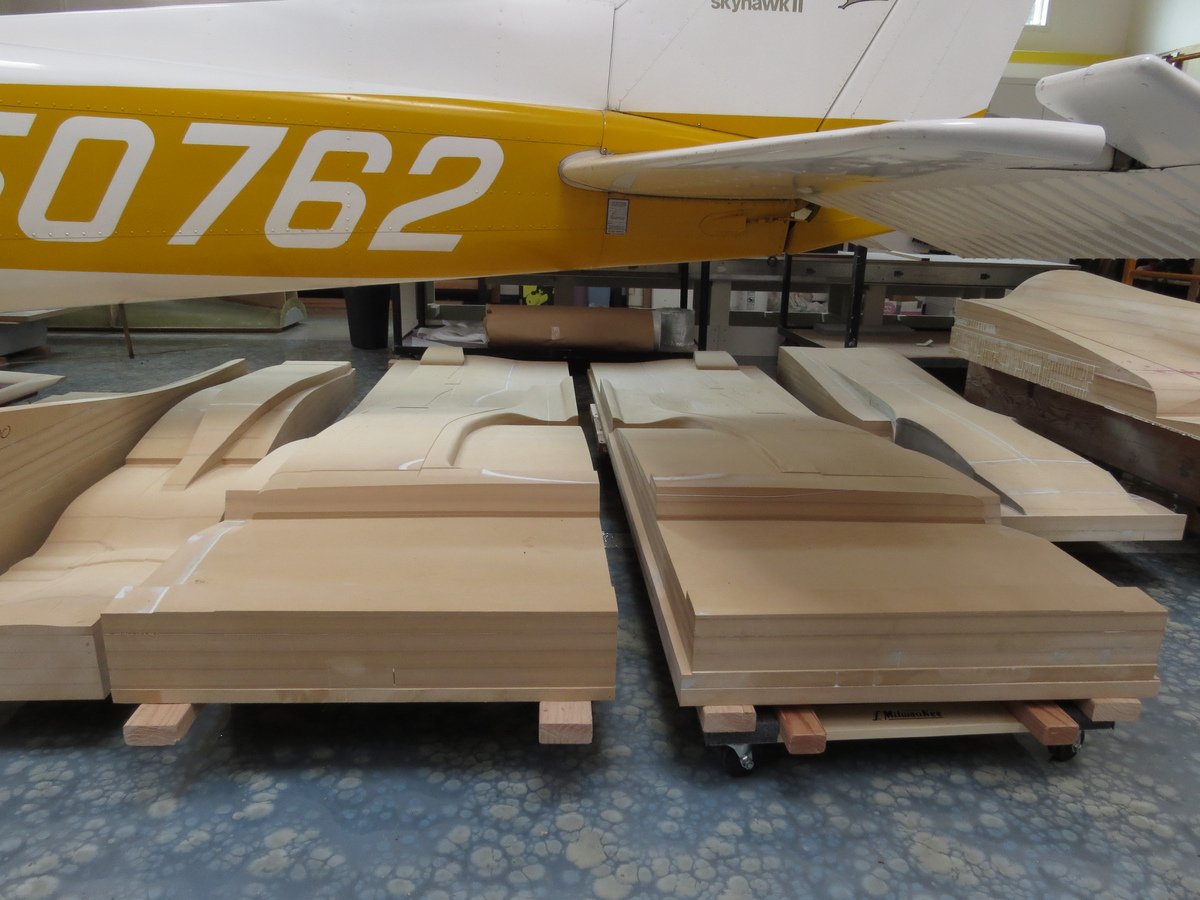
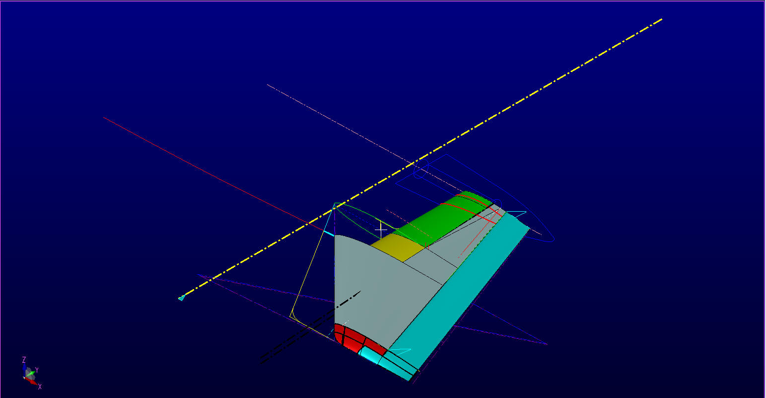
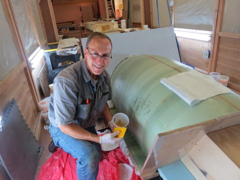
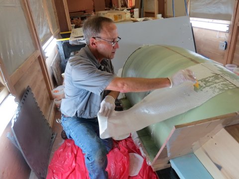
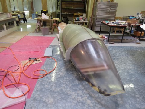
We had to make these in 2 pieces to handle it for transportation and maneuvering in the shop. The final mold will be one piece. The edge closest to the camera is the leading edge of the spar carry through box.
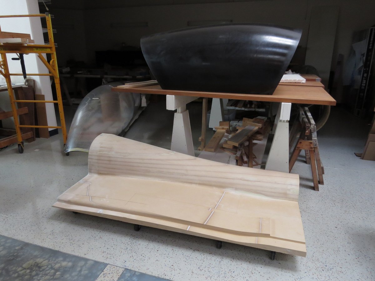
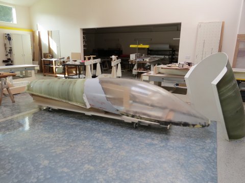
Here is engine access cover. The fiberglass panel that eventually is fabricated from this plug will go on top of the above part and be totally removable to gain access the engine.
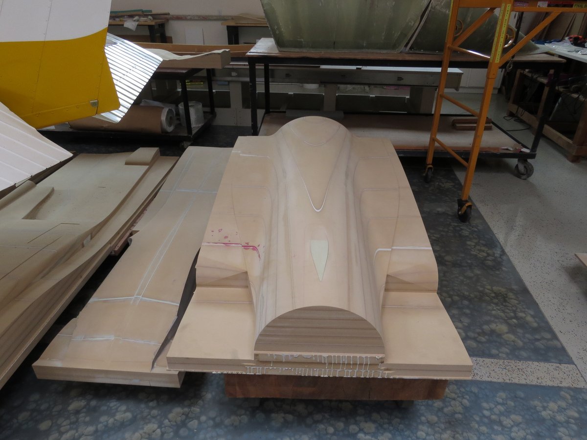
This is one half of the rear fuselage (upside down) that includes lower inboard part of aft deck that will eventually attach to the booms.
8-19-18
Yes, it has been a year since I posted anything about Jeff's airplane. Jeff finally recovered from his disaster!
I talked to Jeff a couple of weeks ago and he has been busy organizing his CAD file. He uses a very dumb direct edit only package I sold him almost a decade ago. Now just because a CAD system is dumb doesn't mean it cannot to the job very effectively. It is based on levels, so if you are not very disciplined the project can become quite a mess.
He sent me the latest file, I have a copy of the original software and decided to see how this would export to ZW3D.
I exported both STEP and IGES. These are the two formats that handle surfaces and 3D wireframe much better than the solids based Parasolid or ACIS translations.
It is interesting that the two translations offer different results.
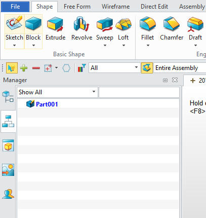
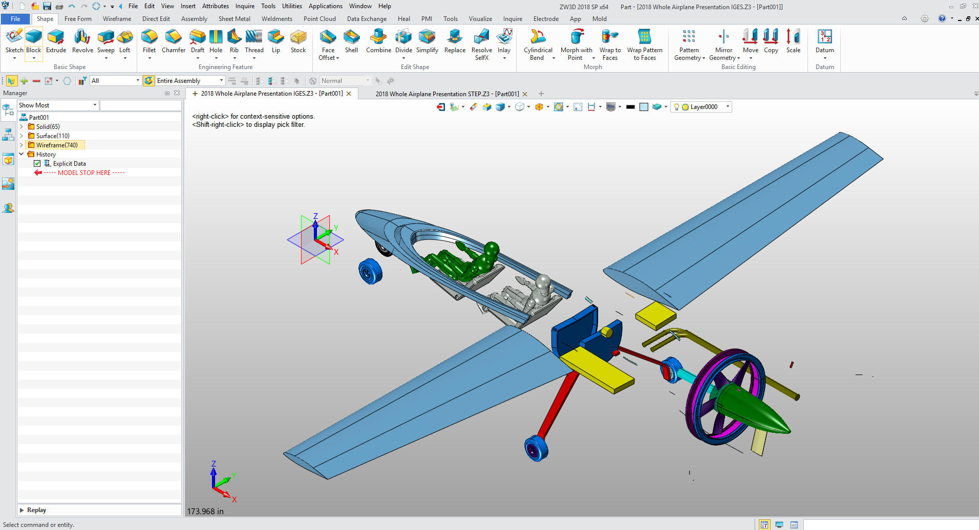
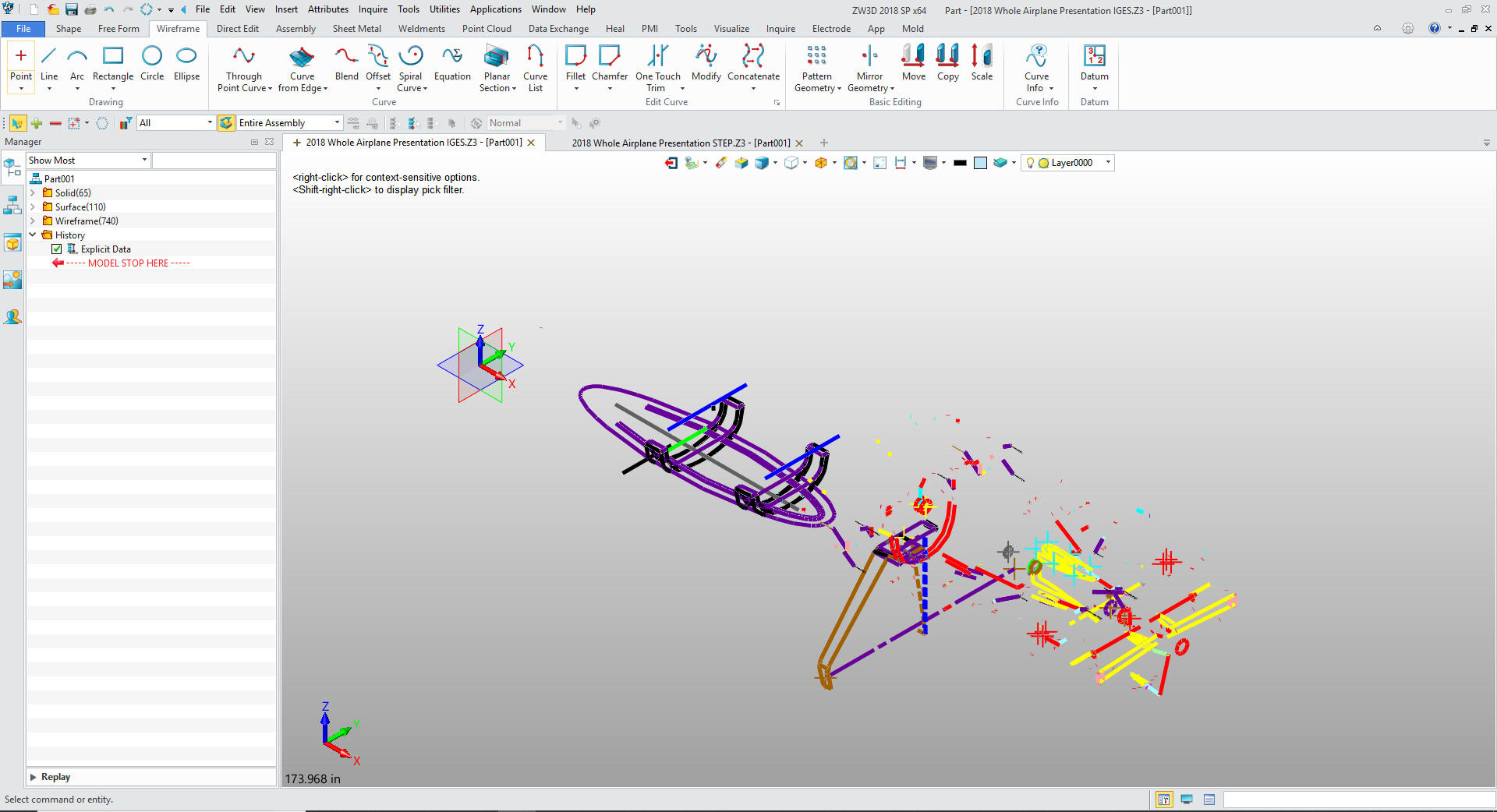
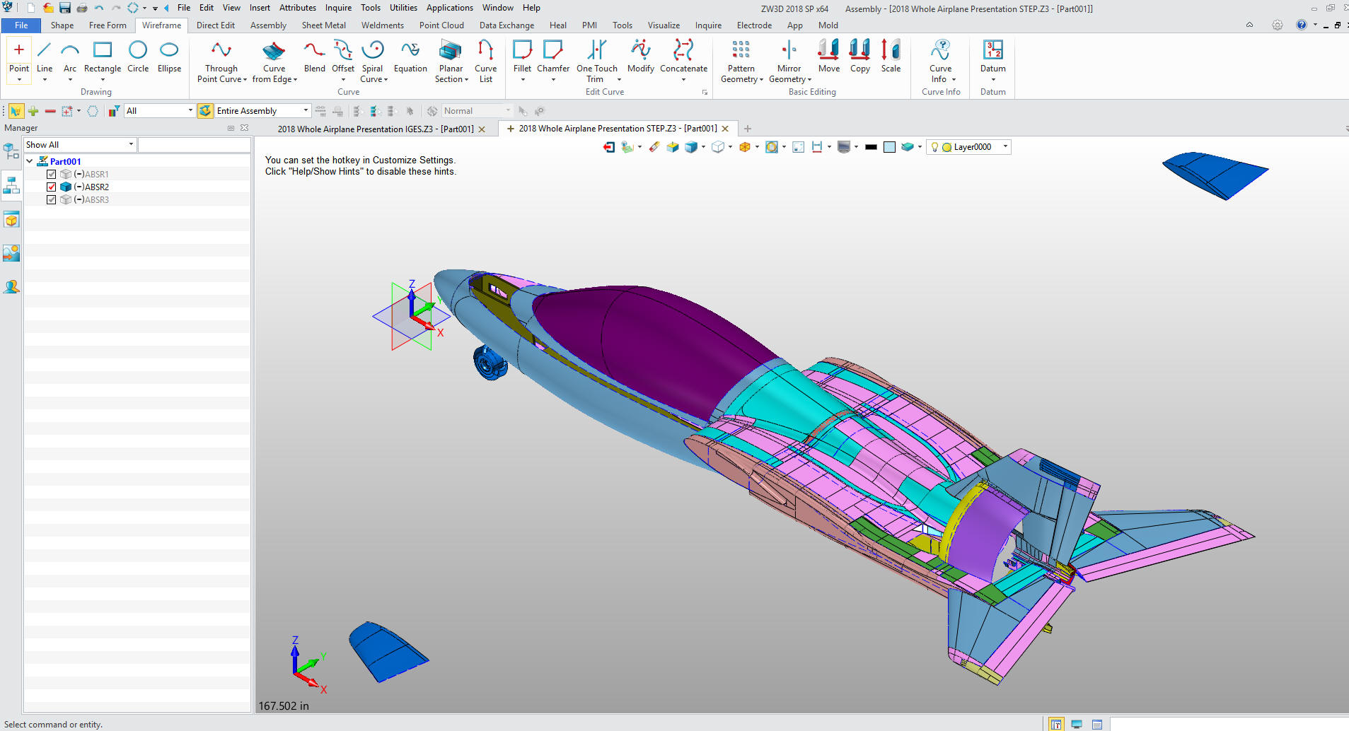
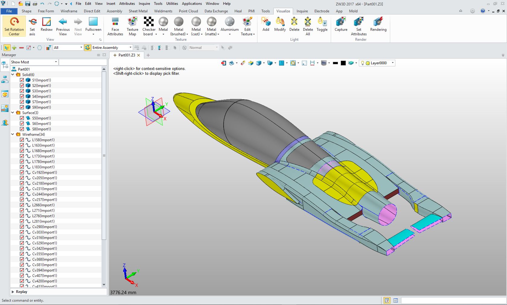
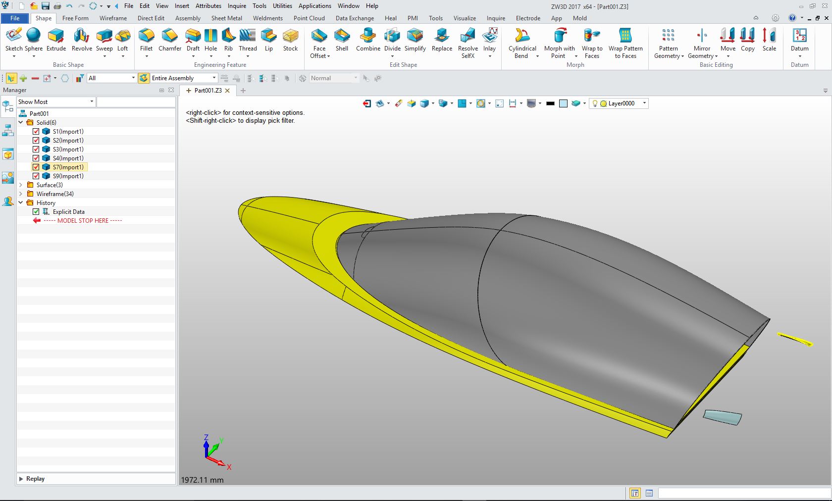
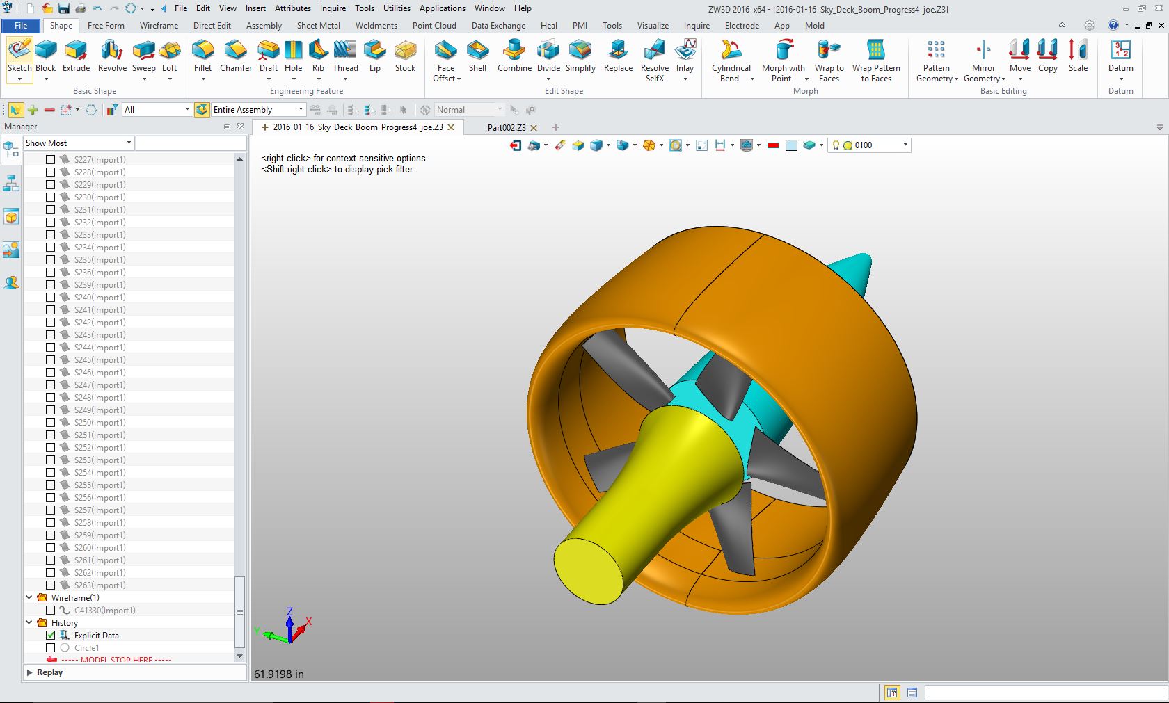
Here is the IGES translation. Both the IGES trimmed surface only and IGES solid had the same results. ZW3D being a standalone surfacing package works very well with other standalone surfacing packages such as Rhino and Alias.
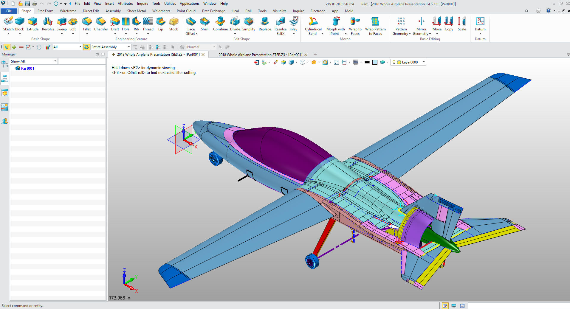
Notice the assembly manager only shows a single part.
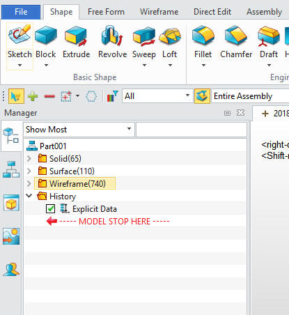
While the history manager shows a variety of solid, surfaces and wire frame entities.
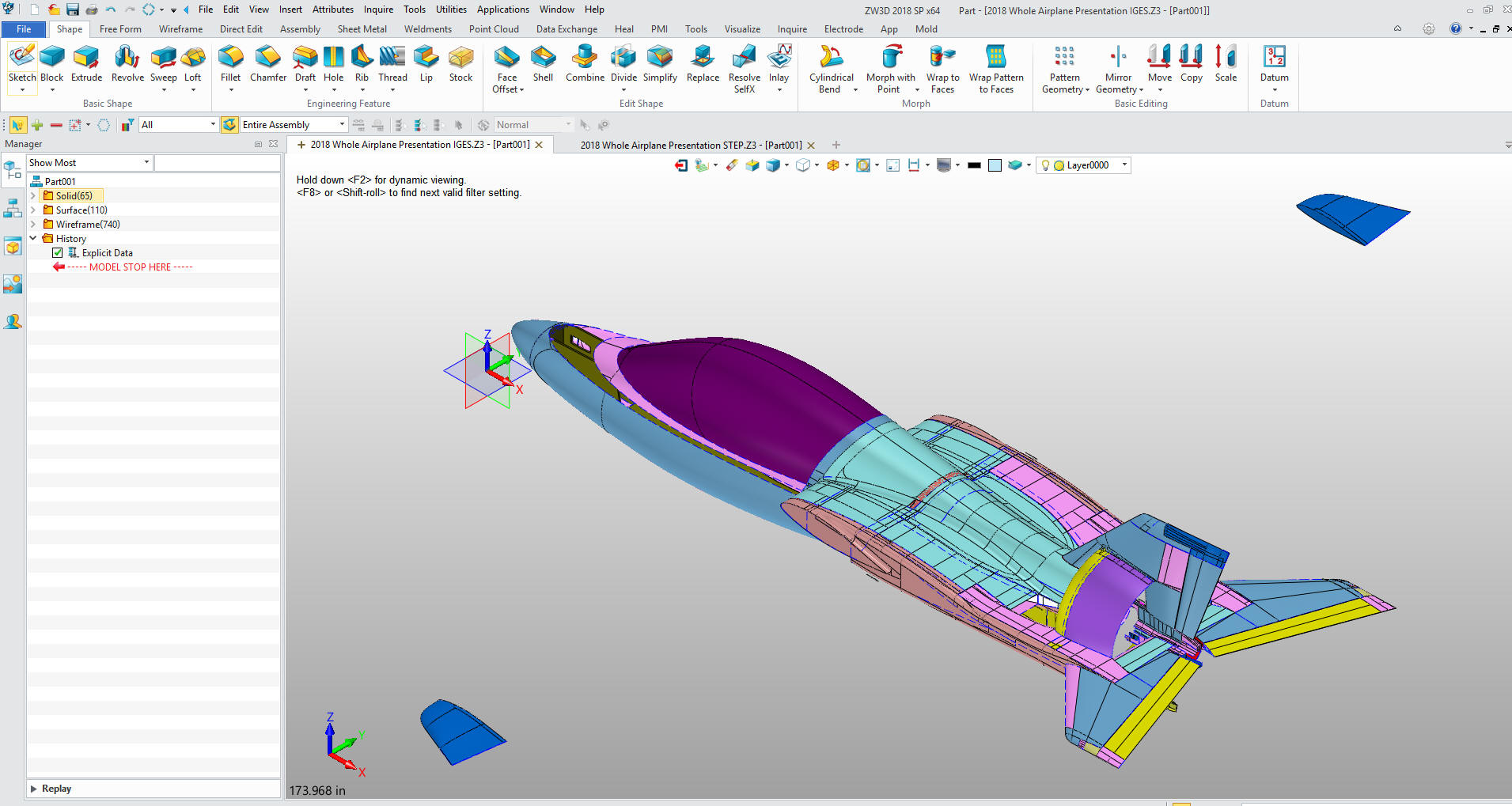
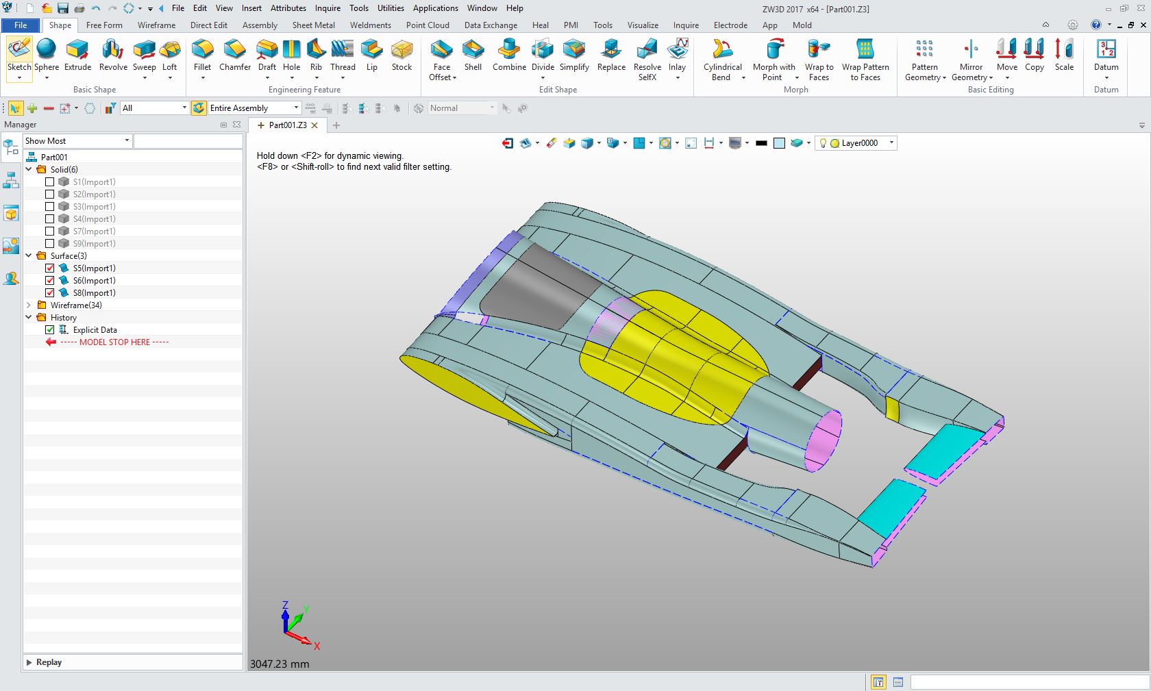
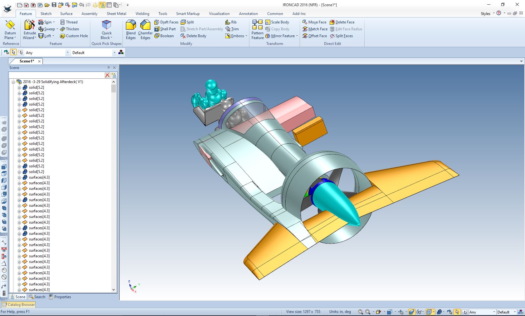
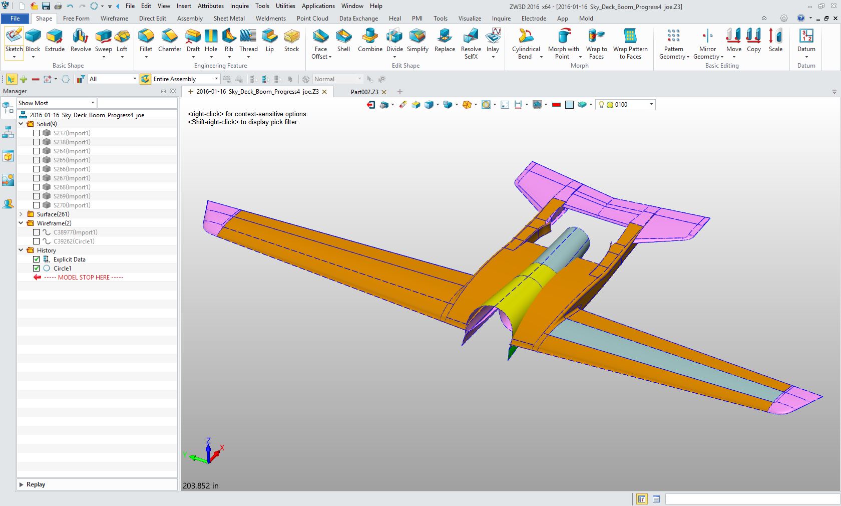
Here are the solid models Jeff defined. This shows the major advantage of ZW3D over Solidworks. The Multi-object environment. As you can see this is just one file where all the entities coexist. The other incredible feature is the integrated AID (drawing) imagine having a complete project or sub-assembly in a single file?
The surface entities
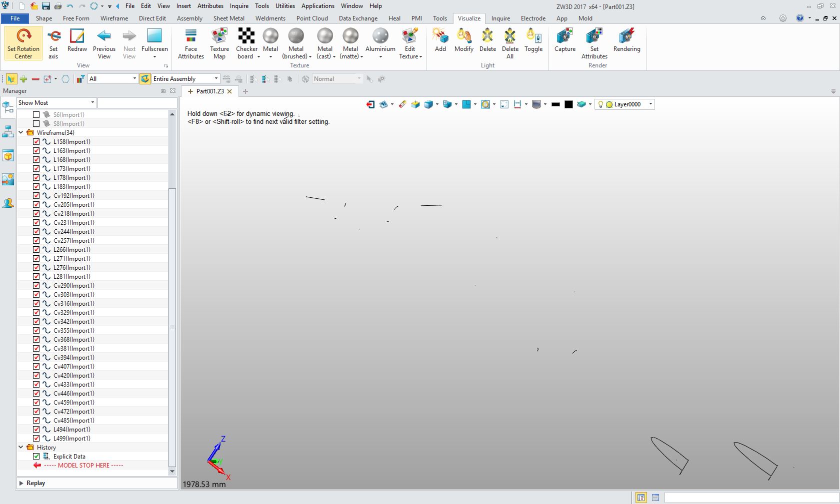
And finally the wireframe entities. ZW3D can freely modify any of these entities. This is due to its incredible hybrid modeling from incredibly smart with flexible parametrics to as dumb as you need it to be! LOL
Now for the STEP file.
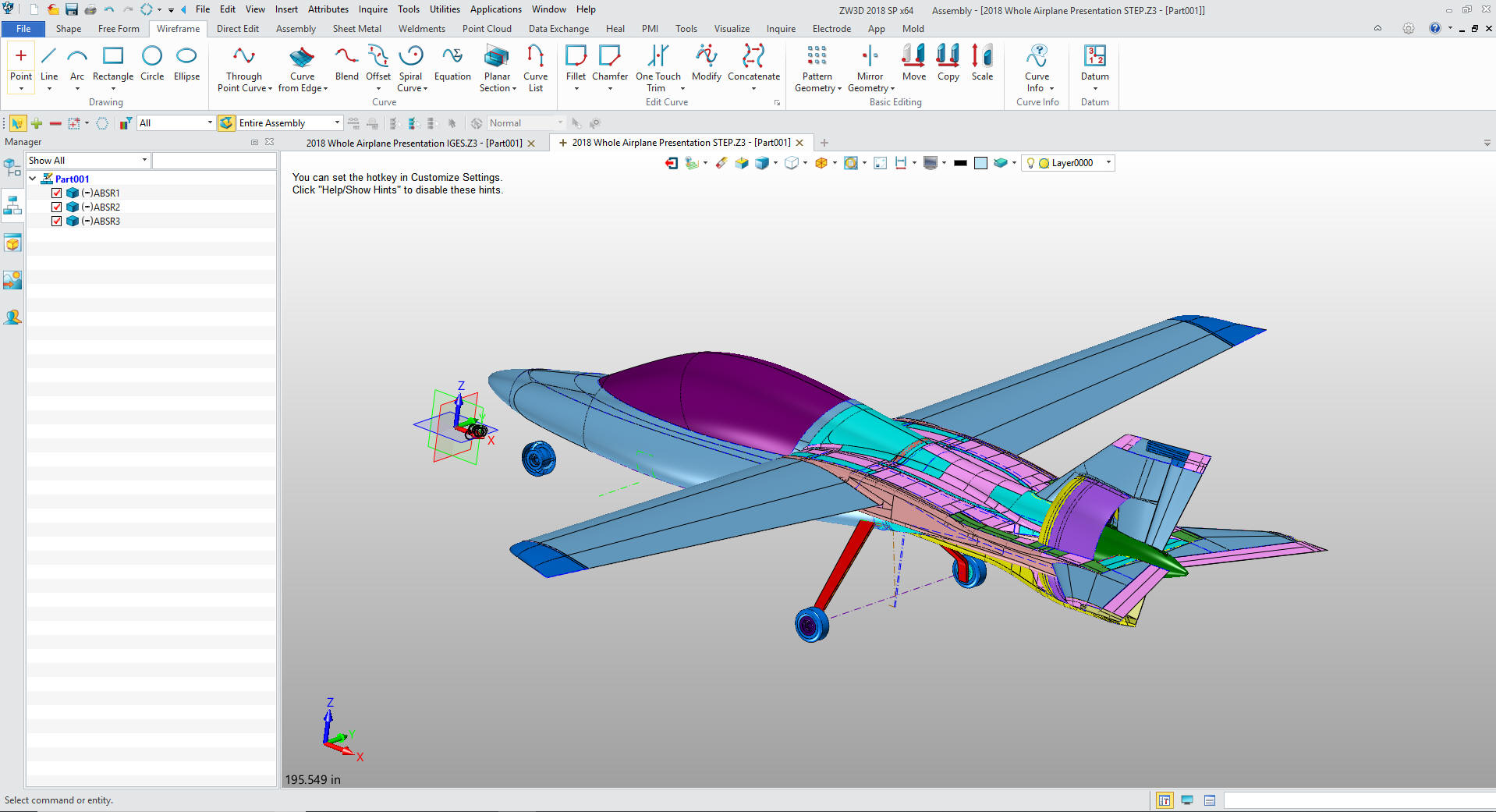
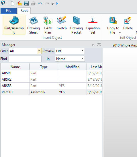
You can see in the assembly manager that it comes in 3 assemblies.
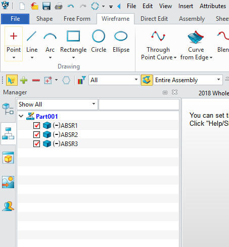
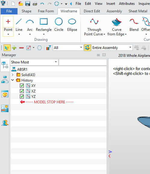
ABSR1 - Shows the solid entities only.

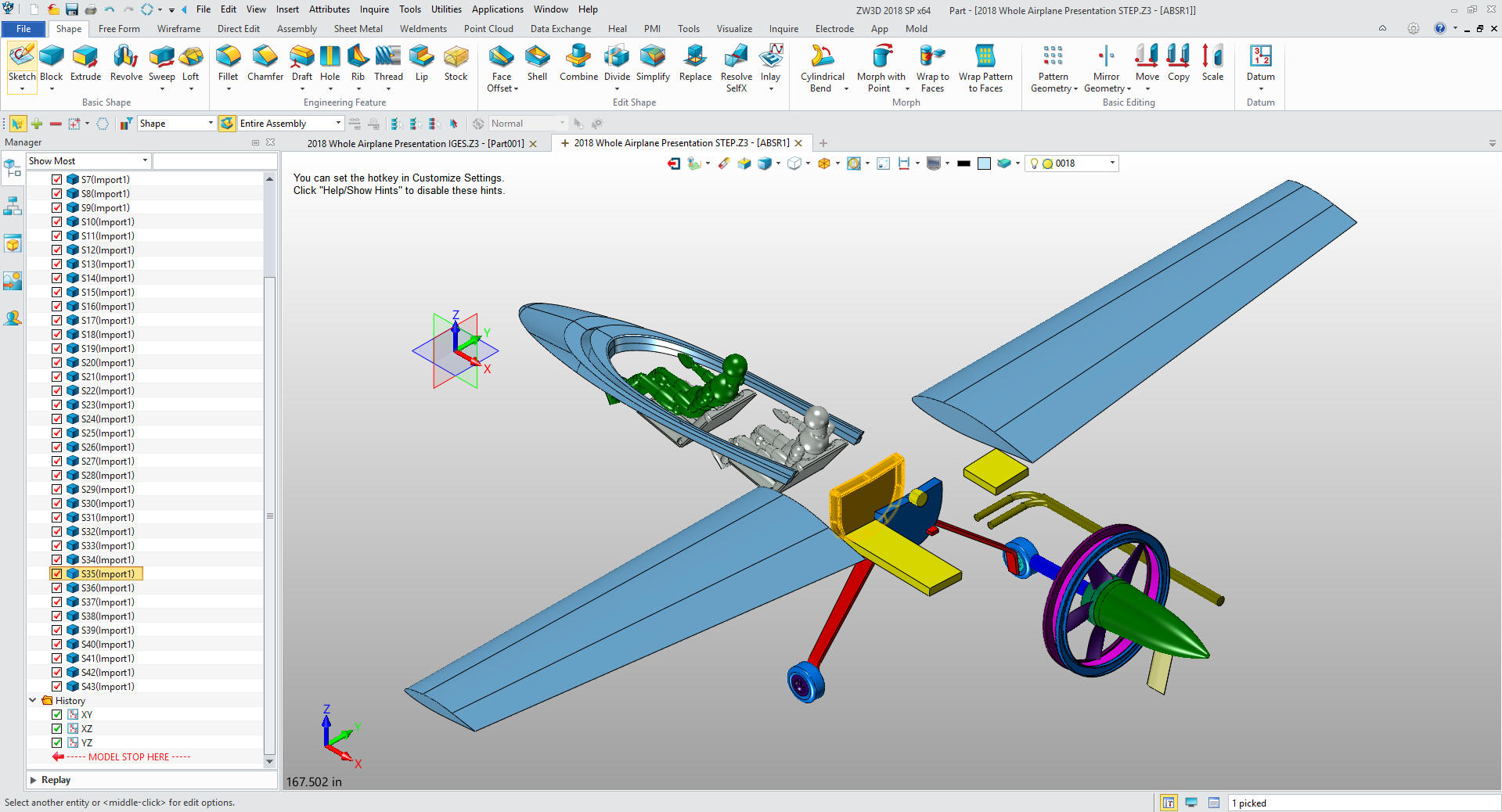
You can see when we open the ABRS1 we only have the solids.
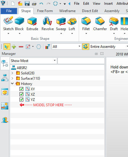
ABSR2 - Shows only surface entities.
You can see when we open the ABRS2 we have the surfaces and 28 features denoted as solids but not shown ABSR1
You can see when we open the ABRS3 we only have the Wireframe. I found I could easily modify the attributes of all the wireframe with the STEP translator converting the entities to solid lines and changing the color to blue. The IGES wireframe did not let me select all of the entities to edit it looks like it came in as a different entity type.
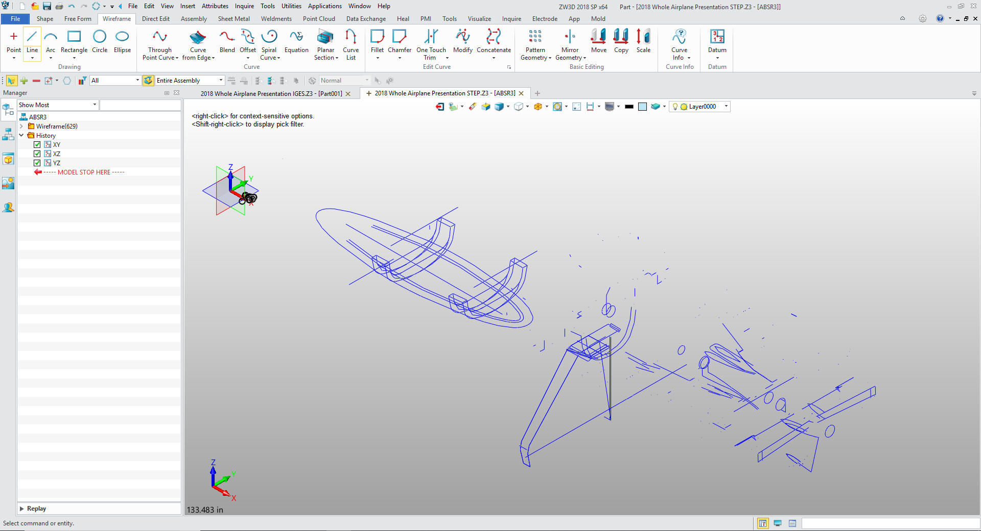
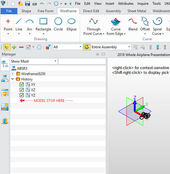
It seems like the STEP conversion offers much more control of the different type entities.
Modification
Now lets do a bit of modification. I will only modify a solid here since surfaces and wireframe are basically generic and can be modified in any good stand alone surface modeler.
Here is the file manager that shows the different parts and assemblies. We will select the ABSR1 that includes the solids.
Now that we have the solid model open. We will pick a shape to modifiy.
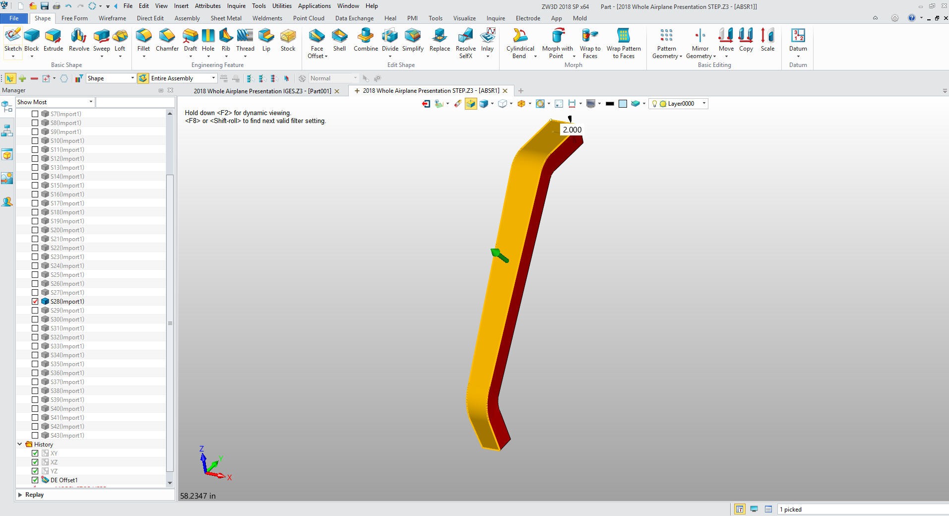
Here is the left landing gear support selected and increased it 2 inches.
You can edit any entity in this file. Can you imagine how easy it would be to work with any system? This is called hybrid modeling. ZW3D offers parametrics, solids, surfacing and wireframe. Plus it has morphing and true reverse engineering.
IronCAD
Okay, okay I will show this file imported into IronCAD. Why would I pick ZW3D over IronCAD. IronCAD like Solidworks and many other system only include basic surfacing to enhance the solid modeling. While surfacing is available in IronCAD it is not a stand alone surface design tool like ZW3D.
As I started the translation I remembered that IronCAD has both the Parasolid and ACIS solid modeling Kernels and have different results.
Showing differences
in Import
Using Dual Kernel and Repair options.
I have found that the original program was only putting out trimmed surfaces and IronCAD in both kernels brought in only trimmed surfaces. So I switch the original program to generate IGES Solids.
Okay, I know I am getting a bit carried away. But now I am intrigued by the different results I am getting.
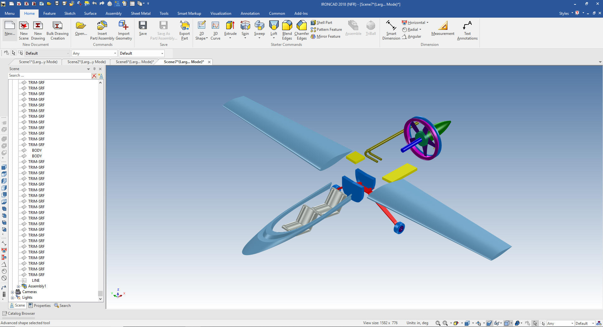
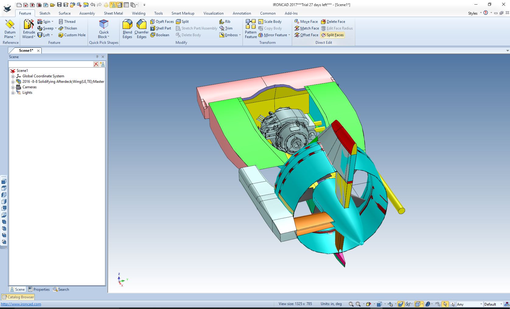
Here is the IGES Solid file imported with the ACIS kernel. Now we have solids and the trimmed surfaces. It shows no difference than the surface only IGES file imported to ZW3D. IronCAD has the same solid models that imported into ZW3D. It is interesting they come in monochrome. The left is the solid models and the right the surfaces.
Notice like ZW3D, IronCAD has all of the parts in one file. IronCAD is one of the few programs that has a true single model environment where all of the parts reside in a same file. This is the most productive design environment. You can have referenced parts in both IronCAD and ZW3D.
Here are the solids and surfaces separated. Solids on the left.
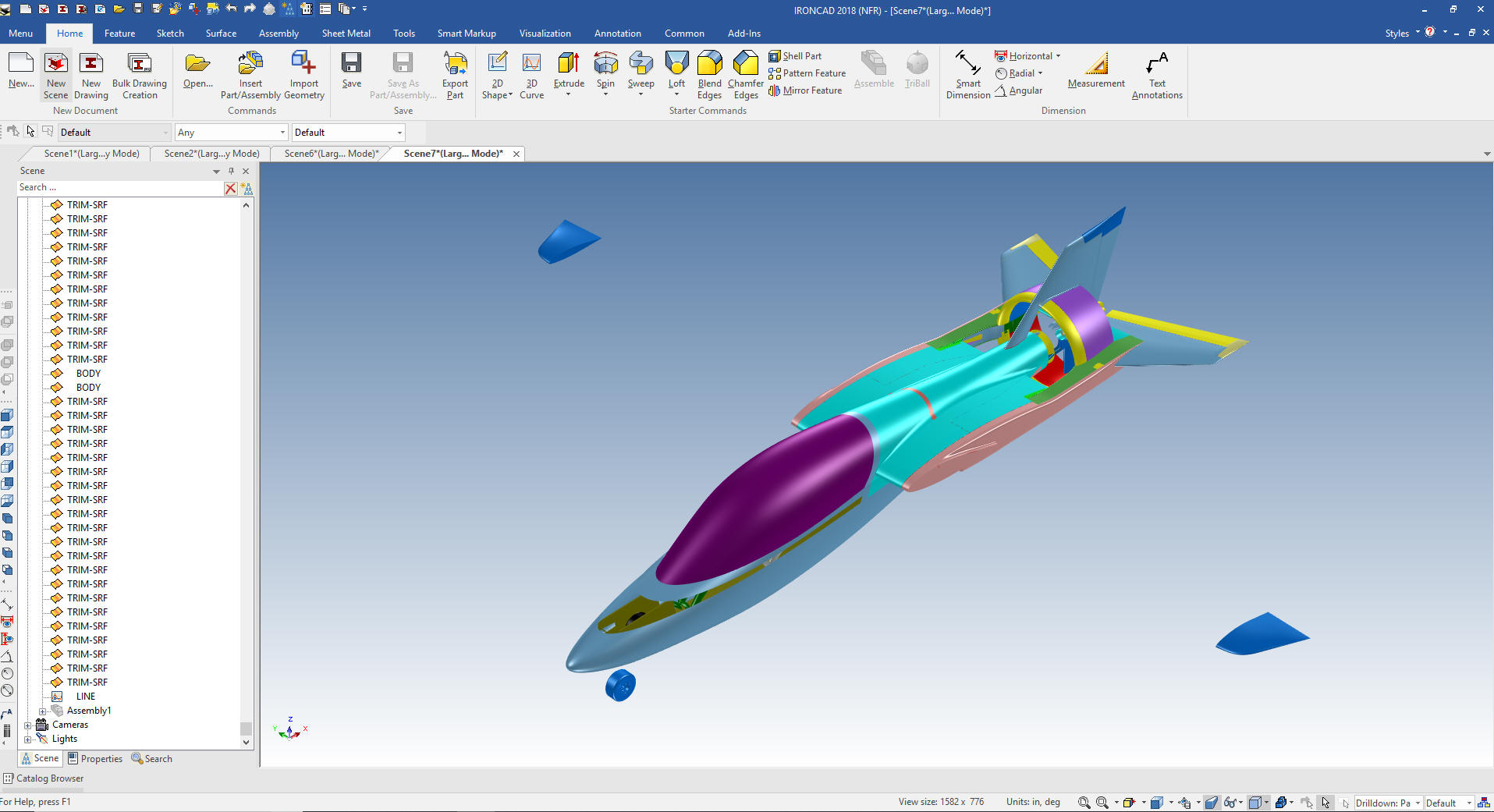
Now for the IGES file imported with the Parasolid Kernel. As you can see the parasold kernel just by adding color offers a much better translation.
Again we show the solids on the left and surfaces on the right.
Now to the STEP.
We will start with the ACIS Kernel. Quite colorful. The ACIS kernel seems to be less consistent as compared to the Parasolid kernel.
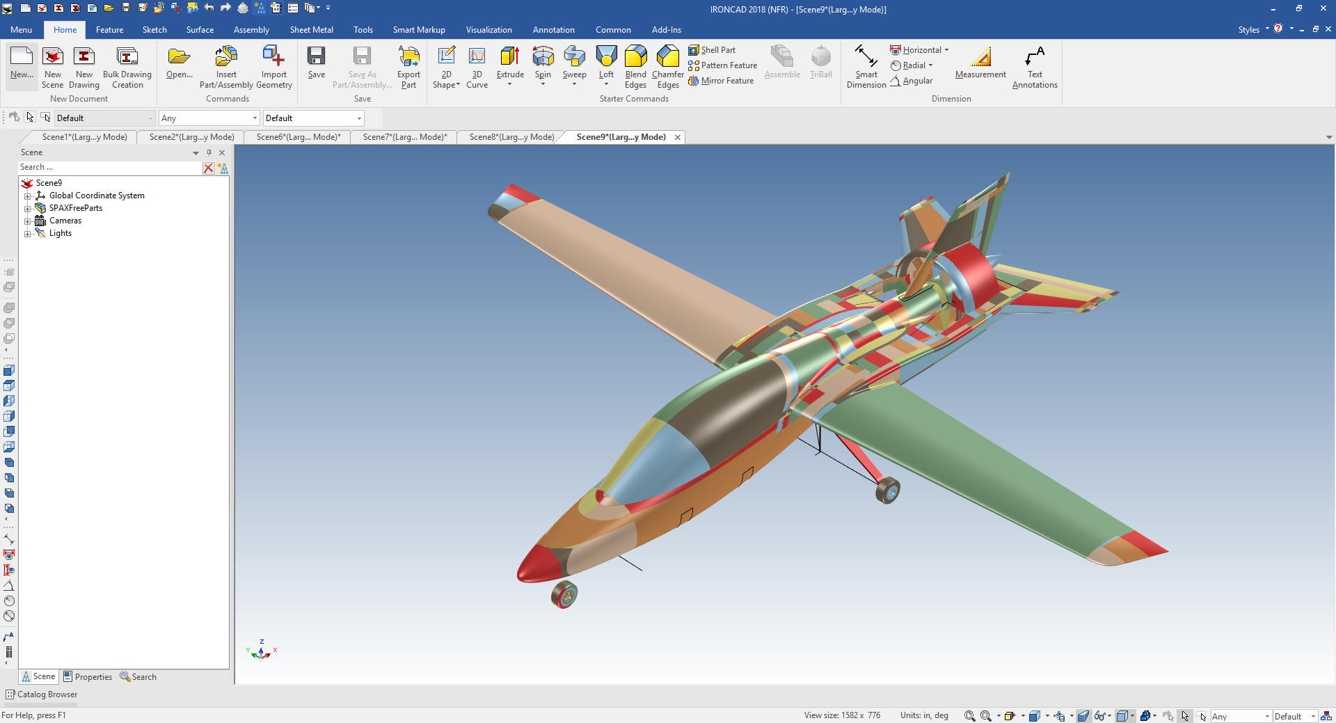
Again solids on the left and surfaces on the right.
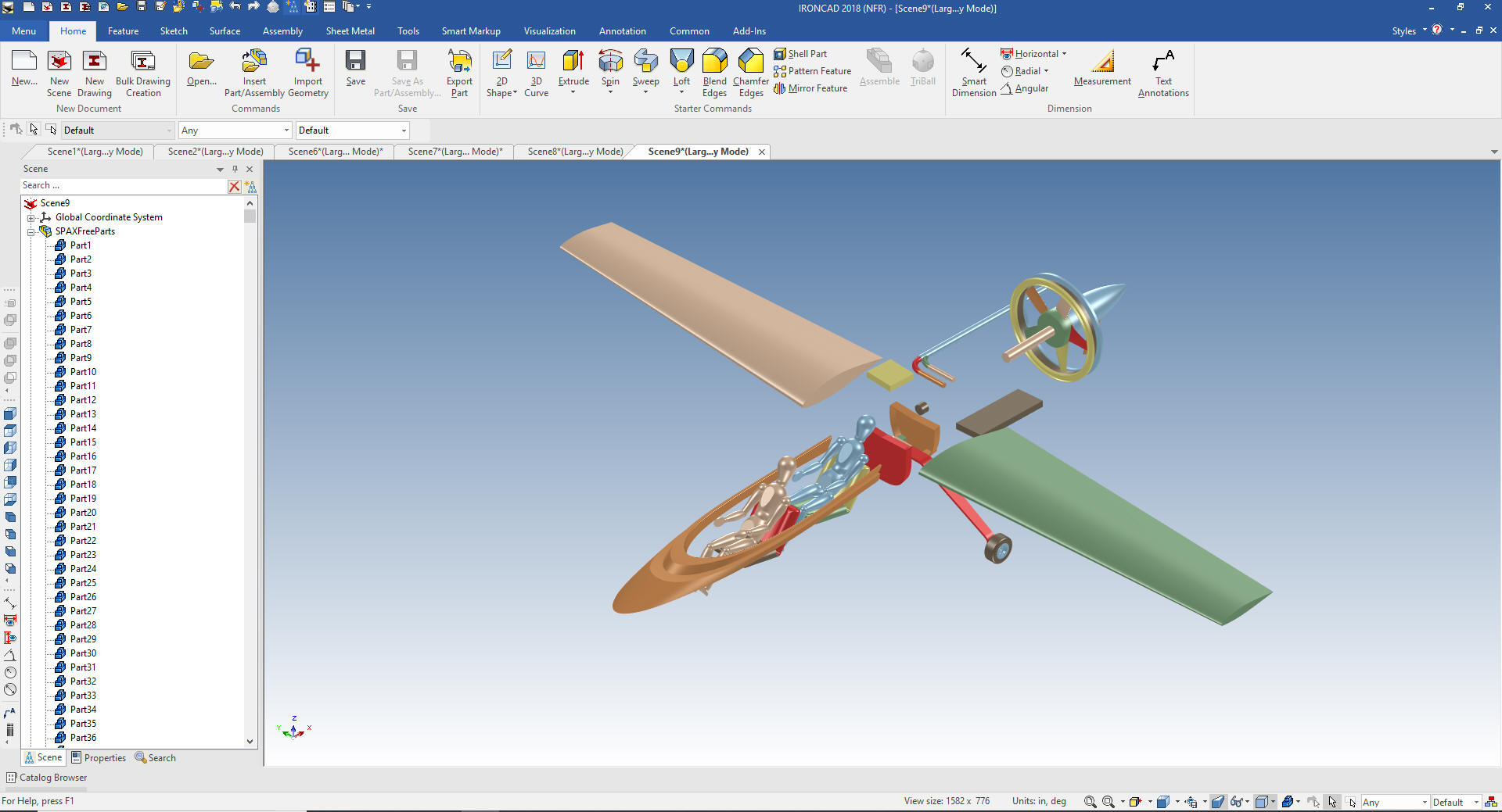 
Now for the Parasolid kernel. As you can see the colors are a bit more consistent with the different parts and surfaces.
Solids on the left surfaces on the right.
So there you go, more than you ever thought you would need to know about IGES and STEP translations, related to the Parasolid and ACIS kernels. LOL
The file size of the different formats is quite interesting.
The Original program - 134,032
IGES Trimmed Surfaces - 110,966
IGES Solids - 104,828
STEP - 87,129
ZW3D IGES - 30,316
ZW3D STEP - 29,367
IronCAD STEP ACIS - 92,832
IronCAD STEP Parasolid - 82,491
IronCAD IGES Solids ACIS - 90,928
IronCAD IGES Solids Parasolid - 82,768
IronCAD IGES Surfaces ACIS - 92,944
IronCAD IGES Surfaces Parasolid - 85,920
You too could have access to this level of 3D CAD knowledge. Just give me a call.
Joe Brouwer
206-842-0360
8-9-17

Disaster Strikes
I started as a draftsman at Boeing in 1965, I continued to work as a contract engineer on the board until 1982, I was introduced to Computervision CADDS 4 and became a 3D CAD design draftsman, I bought an Atari 800 computer in 1980, I moved up to a PC and DOS in 1983, I was introduced to PC based 3D CAD in 1986 while on contract with Boeing and quickly became a dealer, in 1987 founding TECH-NET, we became a personal computer and Microsoft dealer, we were instrumental in expanding the use of PC based 3D CAD into Boeing and the Great NW and we have used and sold every version of Windows,
I have experienced it all. Every computer problem that arose with the PC I suffered through, especially data loss! From the very beginning in Computervision and through out my learning curve of moving to the Personal Computer, these hard learned lessons establish patterns of how to handle your documents. You do backups. Yes, even then, once in awhile you lose some data.
I assume that all know what I know.
I have been working with Jeff on his airplane for 12 years. He recently retired and now has more time to dedicated to the project. He has to split his project time with his two young sons.
A couple of months ago disaster hit. His hard drive crashed. There were frantic phone calls. I would assume that after 12 years and a couple of computers that data, if not backed up, would be available.
I have to tell you i was a bit perplexed at his situation. It was a combination of problems with the hard drive and working with computer technicians. But in the end "ALL" of his data was gone.
I had all of his previous data on my computer and a few of his later concepts that I worked with him on, lately we were using dropbox. He also had a few thumb drives that he would carry back and forth when we worked together.
He probably lost 2 months of work after the dust settled. But he had one costly situation.
He lost the license to his CAD software!! This was for a dongle and the software was version 2009. Of course, the software company would not support him. So he had to bite the bullet and upgrade. Yes, another reason to not trust and to dislike CAD companies. I will not expose this company, but they have burned many bridges and are now resting on their laurels like so many of the major CAD companies today.
So let this be a lesson to all of us.
Back up your data.
It really is not that hard. You should have a cloud storage area if your data is valuable. Engineering data is priceless. Also any passwords or licenses should be available to you in a secure place.
Many of us professionals have lost work and know that it is much easier to recreate it. I was working on Computervision and we were allowed to access the data. I did a half days work. I went into the system and deleted the original file then failed to save the new file. You never saw a draftsman works so fast, LOL
Jeff now has a backup system in place.
Here are a few images of Jeff's new work.
This is the skeg and a cross section of the shroud.
He is developing the radiator tunnel
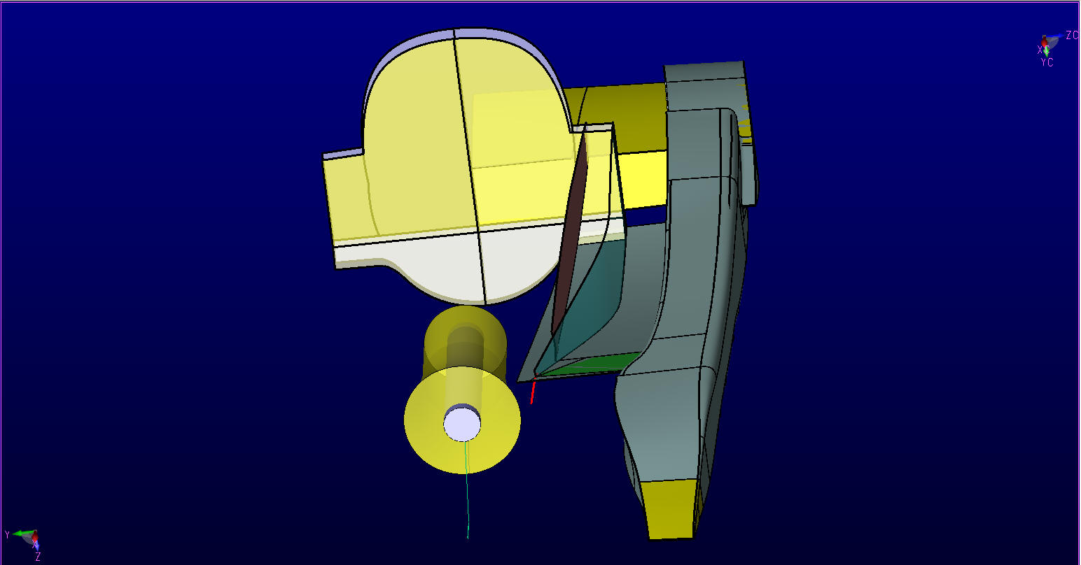
Getting the horizontal tail back into shape
2-18-17
Jeff is applying what I have been teaching him. Surface design can be very tedious. Nothing is associated and can get very tricky. You can see that Jeff is moving right along.
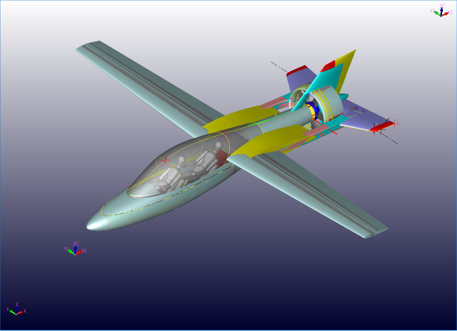
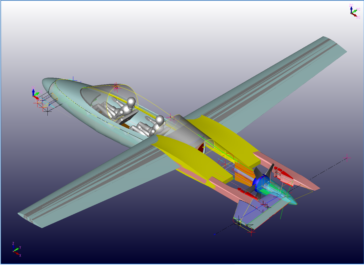
Here are some images showing the different entities that are used in hybrid modeling: Wireframe, surfacing and solids coexisting in one easy to work with space.
Here is the overall assembly
These are the existing solids
The surfaces
Finally some extraneous wireframe
12-3-16
I tease Jeff when he calls by calling him Jefferson!! Hence the new title.
Jeff stopped by yesterday for CAD lessons, lunch and, of course, to discuss his airplane. He has now turned his attention to the aft deck and integrating the drive train into the structure. It is being designed in great hybrid 3D CAD modeler which is the perfect system for aircraft design offering the freedom to work at any level of design from 2D/3D wireframe, surfacing and solids. It is one of the best hybrid 3D CAD systems. I have a copy and an expert with this product after using and selling it for over 30 years.
I am waiting for him to get to the point where I can start helping, with controls, instrumentation and other components. He has recently retired from Delta
Airlines which allows him to put in more design time. I would do most of the design in IronCAD, a much better conceptual design package, and export the design into KeyCreator since that is Jeff's CAD tool of choice. I am a lucky guy to have such great CAD compatible tools available to me.
9-10-16
Here is the latest from Jeff. Jeff is becoming a very good CAD user.
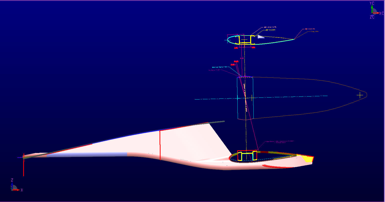
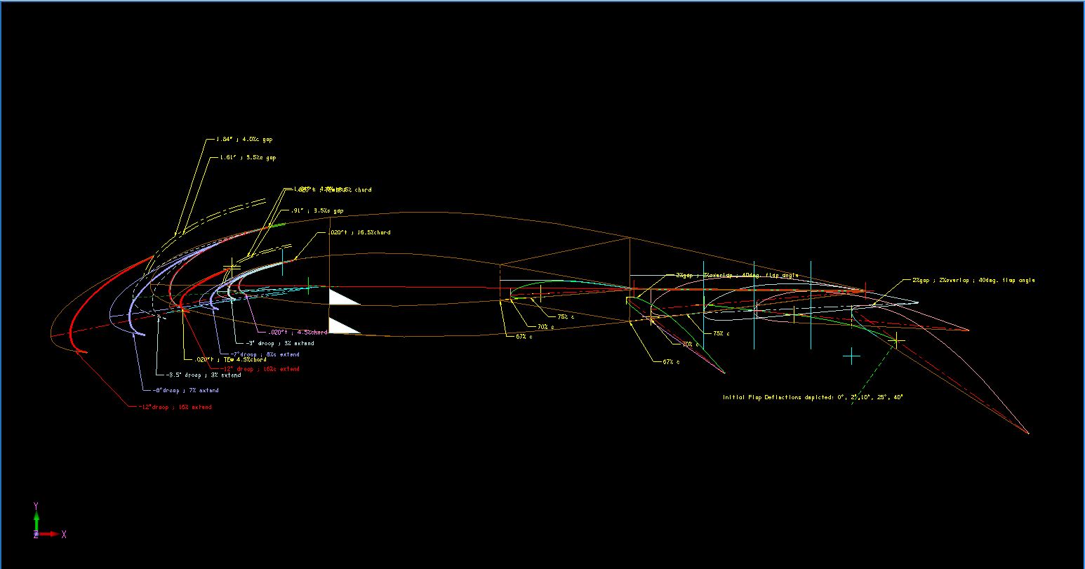
Much of the confidence to proceed comes from an excellent document: High-Lift Systems on Commercial Subsonic Airlines, Sept. 1996 by Peter Rudolph. I took a course with Peter back in about '98 or '99 on the subject of high lift and just cannot help myself. I want to play with the design and actuation of these devices. Some of this is art. Some is referencing engineering studies. The droop of -12 degrees in the fully deployed LE is quite shallow. Commercial airplanes are more on the order of 21 to 38 degrees with slot gaps of 1 to 2 percent. Part of Peter Rudolph's research references a Swedish aerodynamicist, Ljungstrum, who showed excellent high lift results with shallow deployment angles. The catch is the slot gap. In this study you will see in yellow two parallel lines detailed as "4.0% gap" and "3.5% gap". Note that the trailing edge of the fully deployed LE is tucked in at the "4.0% gap". This large gap is necessary to make this system work.... if you are to trust the data!
The trailing edge flaps are more traditional but with 28% fowler motion. The flap is fully coved until deployed at 2, 10, 25 and 40 degrees of deflection.
There is always a shifting of your center of lift (25% chord location) with flap deployment. The trailing flaps always move the center of lift aft. The leading edge flaps alone would move the center of lift forward. In the balance of this design, the LE slats are more powerful than the TE flaps and the center of lift still moves forward. This changes the controllability of the aircraft as the center of lift approaches the center of gravity.
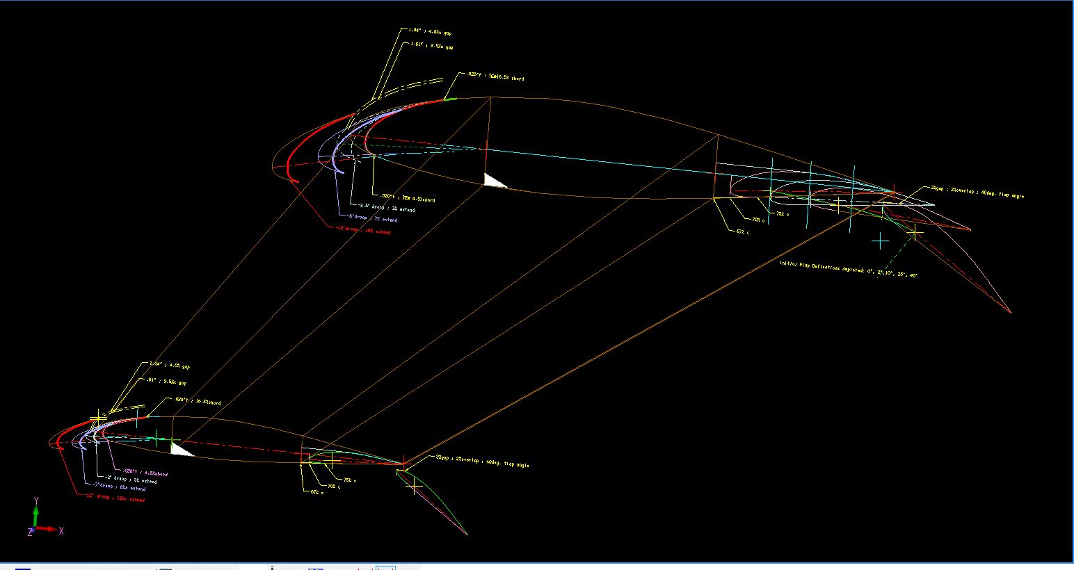
Here is cross sectional study sketch. It is done on two separate planes. This is one of the great features of a hybrid 3D CAD modeler allowing any level of design. This study is done on different levels ready to be used to complete the design in surfaces then solids.
Here is an iso of the wireframe that shows the location of the separate sketches that will serve for the basis of the solid/surface modeling.
6-26-16
Jeff is slowly recovering from the input from the other designer using Rhino. He is quite excited about his progress in both CAD proficiency and the design. As you can see he is moving right along with the aft deck. He will be retiring from Delta this year and will put more time into the design. I am patiently waiting to get this airplane to a level where we can start making it a reality.
To effectively do aircraft design at any level you need a flexible hybrid 3D CAD modeling system. Solidworks was the first CAD system used and the original designer working with Jeff gave up. Jeff bought a seat of Solidworks 2005 and now he doesn't even have it loaded on his computer since we can access the SW native data directly with his current 3D CAD system if needed. Solidworks was virtually worthless since it did not fill the need for flexible integrated wireframe and flexible surfacing. An effective 3D CAD system should be able to use 3D CAD graphics from any system and treated it like natively created graphics. The Pro/e clones have a long way to go, if they can even get there.
Here is his latest work.
Jeff is not the only one of my friends designing airplanes. Selcuk Ozmumcu uses ZW3D's flexible hybrid modeling to create his new FreeWing Jet Powered Glider and many more projects. Selcuk is an incredibly creative industrial designer and is the most proficient and prolific 3D CAD modeler I have ever met. He is truly a master 3D CAD user. He actually shows the process he goes through to create this and many of his projects.
Concept | FreeWing
4-9-16
A Paradigm Shift
Jeff called "Joe, I am very frustrated" He proceeded to explain the problems he was having with the work from another designer he was working with. He just could not work with surfaces. We planned a get together.
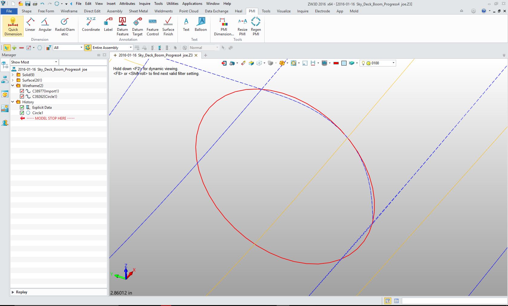
Here was the latest model.
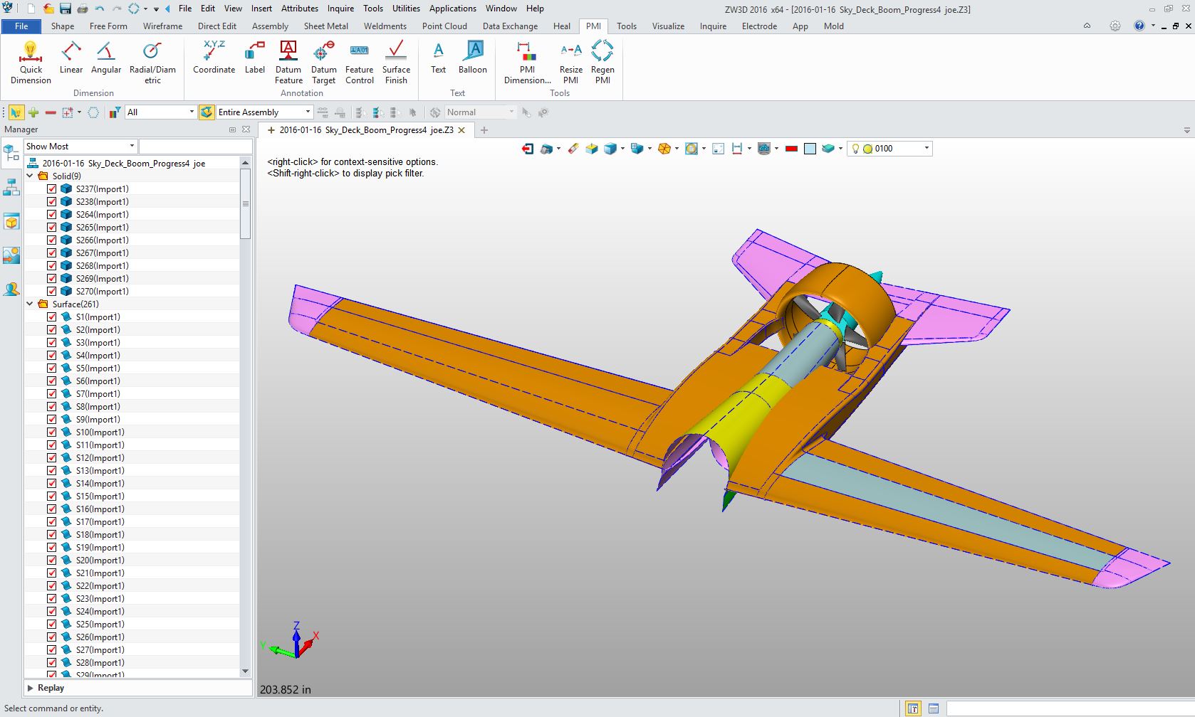
Jeff was having a hard time working with this fellow and working with the design. I took a look at the work and found the fellow used weighted or conic blends. As you can see the difference below, the blend in blue and the circle in red.
You have to ask yourself, "Why would this guy use a weighted blend".
For the life of me, I have no idea why!! We are hardly concerned with aesthetics!
The Weighted Blend
I have had other problems with the use of weighted blends.
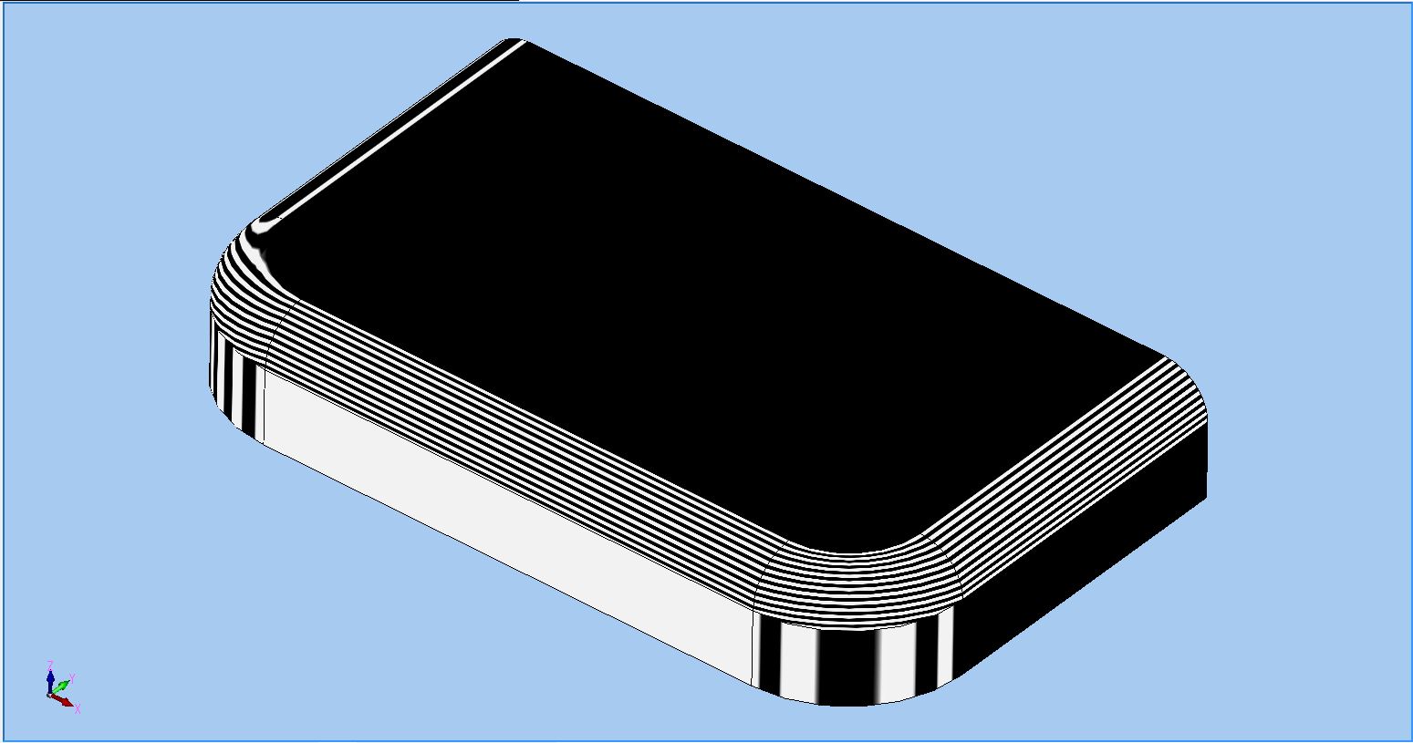
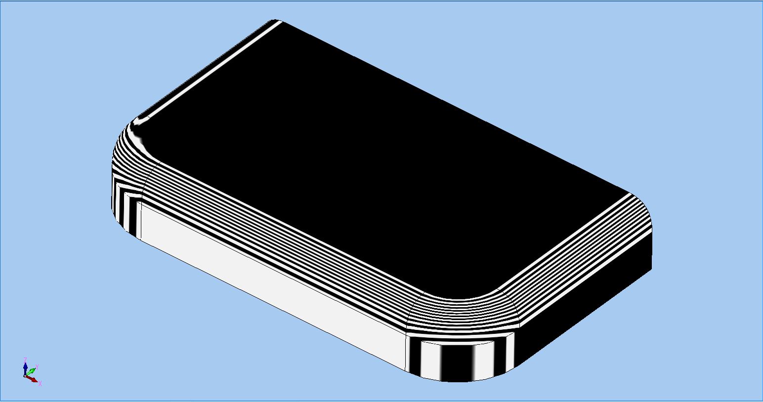
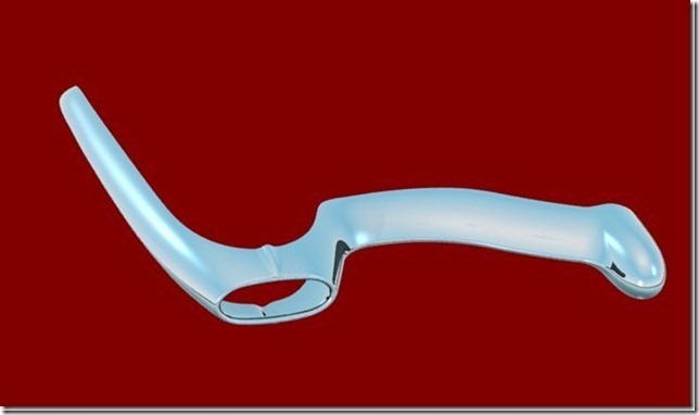
I was hired to do some modification on a finger stylus. This was a device you would slide on the tip of your finger to use on touch screens. You can imagine it was very small.
All of my CAD systems have direct edit functionality. We needed to make a few small changes. The plastic mold designer was having problems working with the original designer. Many times the designer is just "done" with the design. I am sure many of you Pro/e clone users have experienced that!!
It was done in Solidworks (we did not have the original SW file). I started to eliminate the blends or fillets. They would not delete. These were R .008 blends. With further investigation I found they were weighted blends on top of weighted blends. Who in the world would create "R .008" or "R .022" weighted blends? I was dumb founded. Hmm, when you zoom in things really look big!!
Think I am kidding??
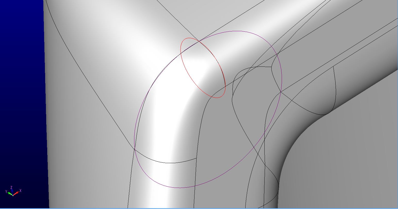 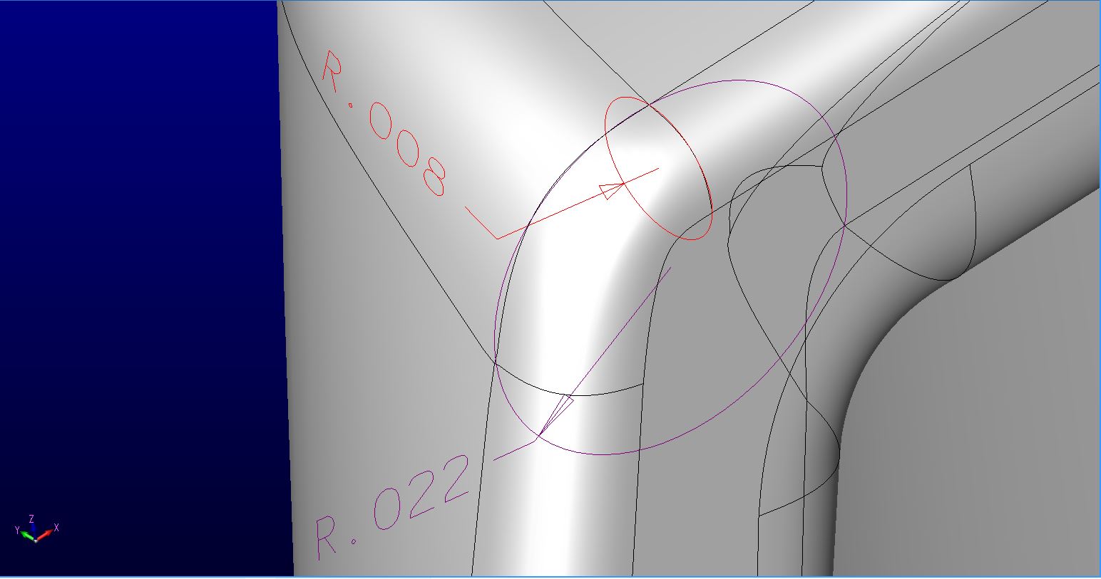
What was going though this guys mind? These could not be deleted by direct editing. If they were standard fillets it would have been no problem.
Weighted blends are mostly used by industrial designers to make sure there is no tangent lines to distort the visual flow lines. I am probably using the wrong terminology. But here is the difference. The image on the left is standard blends or fillet the right is the weighted blends. You can see that the weighted blend gives a better visual effect and can be easily manipulated to create a more desirable effect.
I do wonder if this is nothing but a graphical presentation function and has nothing to do with reality in the machining of the parts. Who do I ask? The CNC folks don't care!! Inspection? I hardly think they are doing a study in visual effects. This seems to prevalent in the automotive body design. Maybe those folks have an answer.
But to use these for no reason is incredibly silly. In the finger stylus could a weighted blend this small even be noticed? Of course not.
On Jeff's airplane was it functional? Of course not.
Most of us will never use a weighted blend, nor will we need to.
Back to Jeff's Problem
I showed Jeff what the fellow had done and it was like a light went on. "These self defined surfacing experts seem not grounded in reality." Just because we can do something doesn't mean we "have" to do it.
We need good hybrid modeling to do much of the aircraft design. We need the ability to use wireframe, surfacing and solids interactively. But the goal is always to create a good editable solid model. Real world parts are not surfaces they are solids. I have to admit a few times in the past I have left the part composed of surfaces not being able to heal them into a solid. But today's CAD solid modeling kernels do a great job of healing.
Here are the solid parts (left) and the surfaces (right).
Who ever thought this would be a lesson in weighted blends??
1-30-16
Jeff has been struggling with getting the design the way he wants. Most of the problems is with the lack of 3D CAD knowledge. He is using one of the best hybrid 3D CAD modeling packages but finds himself stuck in self-created corners.
Using 3D wire frame, surfacing and solids together requires extensive experience. As many of us know we can spend hours to figure out how to do something and it ends up taking 15 minutes to do the process.
Surface design can be a profession. It has levels of proficiency from just enhancing your solid modeling to full surface scupturing. Airplane design requirements are basically in the middle. Most mechanical engineering surfaces are not arbitrary but driven by the precise requirements of the design. While this can be simple to those that are expereinced it is very frustrating for those that are not.
Jeff pushed me out of the loop, thinking the grass is always greener. He picked up a fellow with a more "Proficient" surfacing system. Surface design can be tedious, frustrating and time consuming if the tool cannot do the job. The fellow left him a bit high and dry.
Here is a job that where I needed the help of an Alias expert.
REVERSE ENGINEERING SUCCESS!
1959 Corvette Bumper
I actually started working with Jeff after the original Solidworks designer just gave up. To do this kind of work requires a functional integrated hybrid 3D CAD modeling system.
Jeff is going to come by next week and go over some of his problems. It should be fun.
Here is Jeffs latest work. You can see where the blends are being applied. But there are many transitions that need free form surfacing.
.PNG)
11-1-15
We had a great conversations about cooling intakes after I saw how they handled it on the P-51. Here is the picture that sparked my interests.
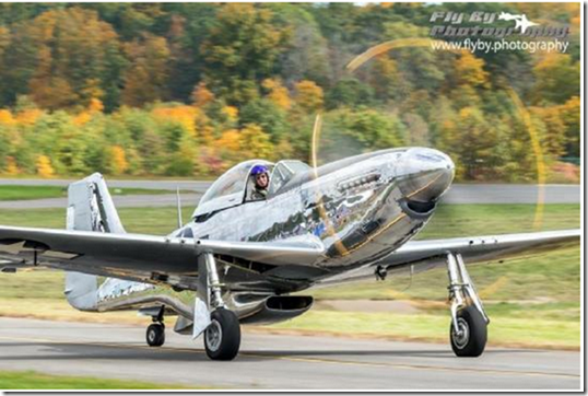
Jeff looked into this question on cooling intakes and this is what he found.
"Just read an article about boundary layer thickness on airplanes. It reconfirms my idea that a "diverter" or fence would not be necessary for my scoop under the wing as regards air entering from under the wing. With such a short run of air from the wing leading edge to the scoop entrance, the boundary layer will have grown to less than .5 inches. That in my mind does not call for a diverter.
That same boundary layer growth along the fuselage to the side of the scoop will have a boundary layer growth to almost 1.5 inches at the scoop to fuselage juncture. That calls for a diverter of fairly small size and as well I would take the "low energy" boundary air and divert it into the engine enclosure that is already turbulent in it's flow. The engine cooling air exits at the gap just prior to the propeller - this part of the design was thought out some years ago ... also with some conversation with my aerodynamicist friend, Dave Lednicer.
The P51 scoop shows a boundary layer growth to greater than 4 inches. But look at the length of run from the nose of the aircraft to the scoop location. That length (and the turbulence from the prop blast) is the determining factor in boundary layer growth."
Here is Jeff's latest work on the aft deck. Jeff's has been using 3D CAD for quite a few years and he finally decided to take it serious and become a 3D CAD designer. I had to drag him kicking and screaming.. LOL.
9-6-15
Jeff is mostly done with the Canopy, but now needs to work with the aft deck as it relates to the new Canopy. Back to 3D CAD to work it out.
3-28-15
We haven't done much with engineering but I thought I would give an update.
Jeff is a hands on guy and wanted to get started. I am waiting for him to get to the point where we get back to designing the controls, instrumentation, landing gear, engine installation, propeller, etc.
I did talk Jeff into sending some pictures of his progress.
“The canopy is a test copy of an F-16 canopy that was used in destructive testing prior to being discarded to a junk yard in Weatherford, TX (30 miles west of Fort Worth and General Dynamics where the F16 was built). I have had it for a few years now.” Jeff tells me.
This canopy is the basis for Jeff's airplane. Everything is built around it. Not that it is going to be used, but it was a great starting point. See a few more picture of Jeff and the project below.
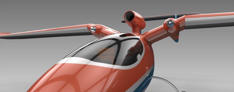
Renderings done in IronCAD
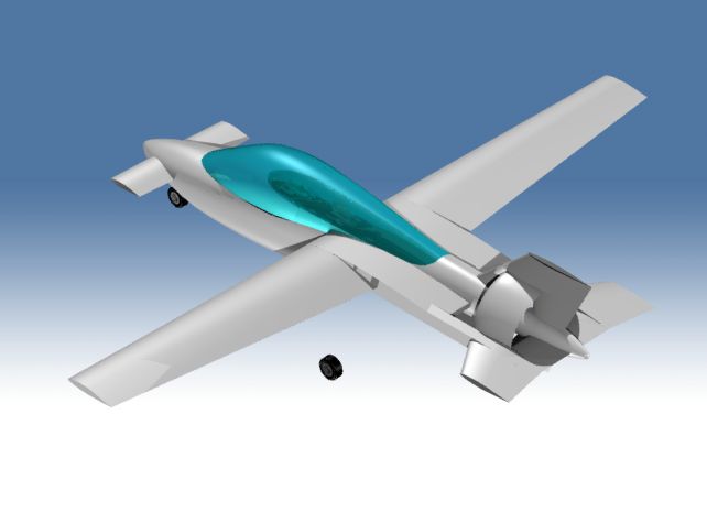
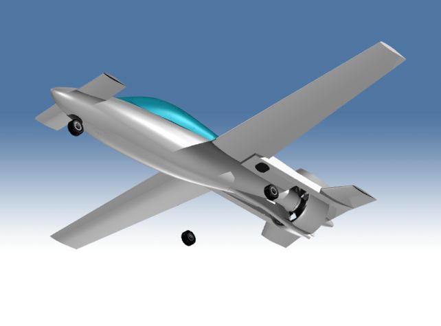
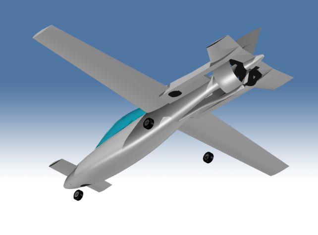
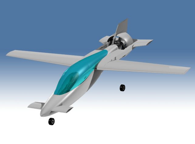
Here are a few Pictures of Jeff working on the airplane:
Have you dreamed of designing your own:
Airplane??
Car??
Boat??
Widget?
If you want to see pure creativity, meet Selcuk!
The Most Incredible Presentation of Hybrid 3D CAD Modeling, Ever!!
The Ultimate CAD System
You can start today!
Myth: Professional 3D CAD is out of your price range?
ZW3D is busting that Myth!!!
You can now have your own Professional 3D CAD system
at a price even your spouse would not object!
ZW3D Lite $1,295.00
ZW3D Standard $2,495.00
You will probably need the Standard Version.
Airplane design can require extensive surfacing!
ZW3D Standard's Hybrid Modeling will never leave you in a Corner!!
Shhh, don't tell anybody, but it is a better system than Boeing or Airbus use!
Beyond Direct Edit: Surface and Hybrid Modeling
Check out our specials here!
Interested in designing a sports car??
Start here -
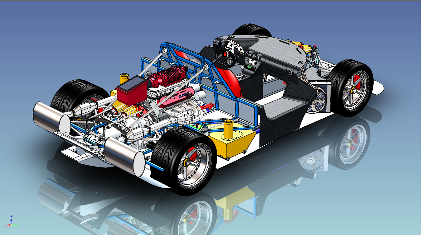
Redback Spyder -
An Australian Supercar
You may have an idea for the next incredible widget!
Put your brand new 3D printer into action.
You can do it all!!
Here are a couple of articles comparing the advantages of our products!
The Worst to
Best 3D CAD System and Why!
LEARNING MECHANICAL 3D CAD
IronCAD vs Solidworks and the Pro/e Paradigm
Incredible 3D CAD Combo
Take a look at the above article it has some great examples of interoperability!
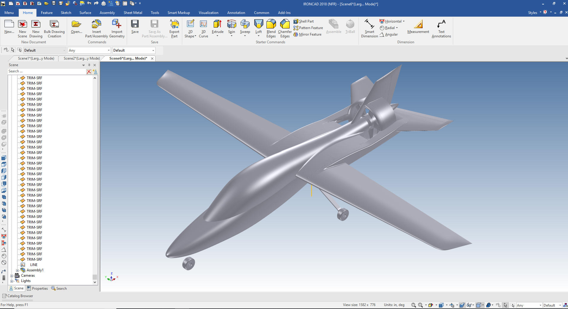
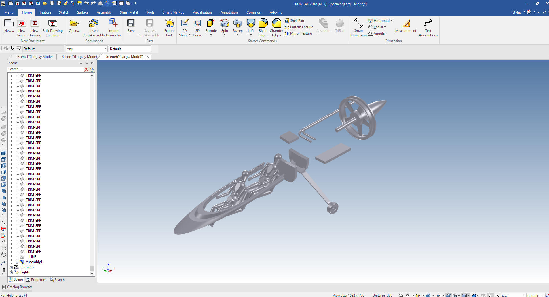
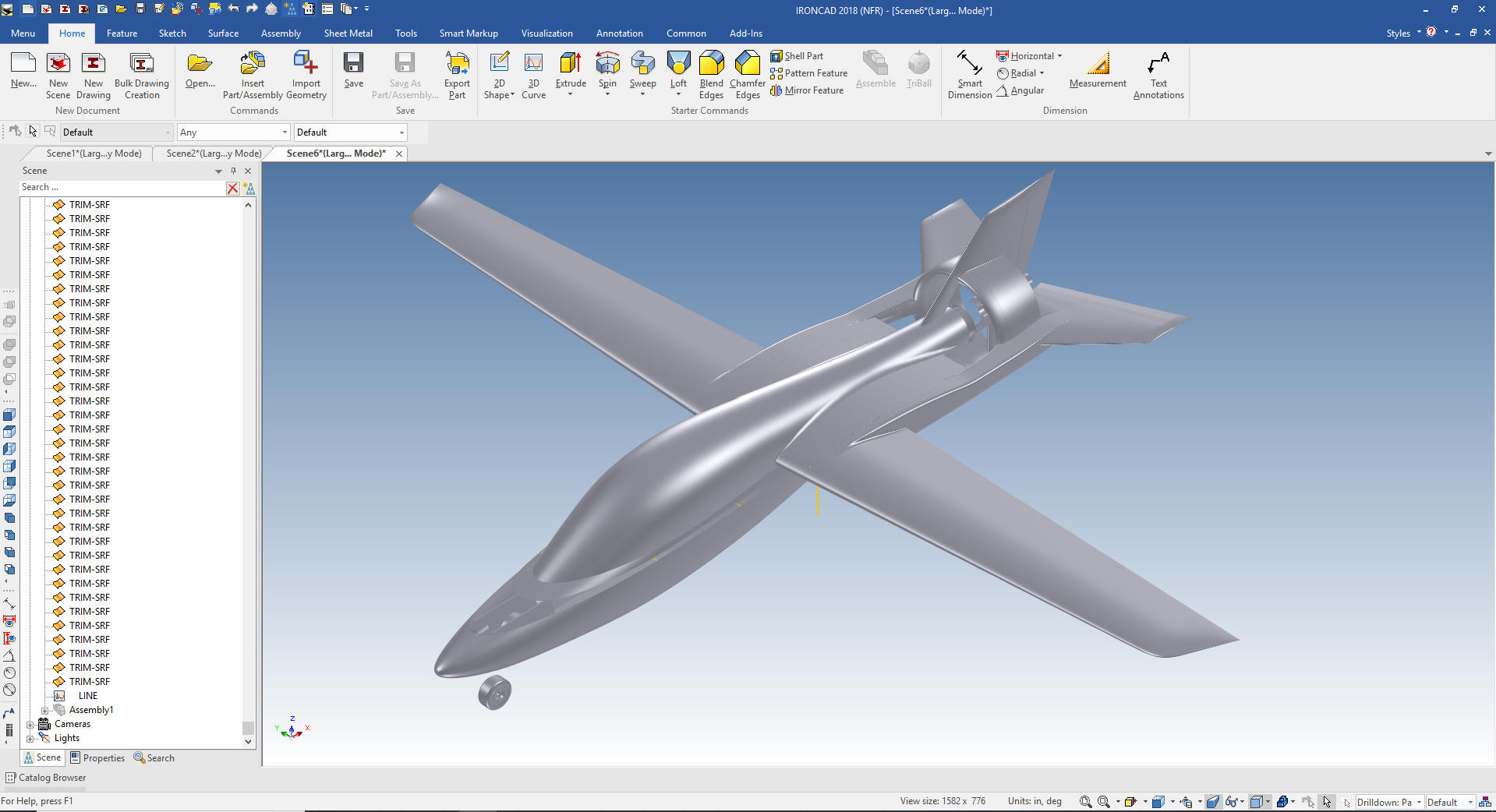
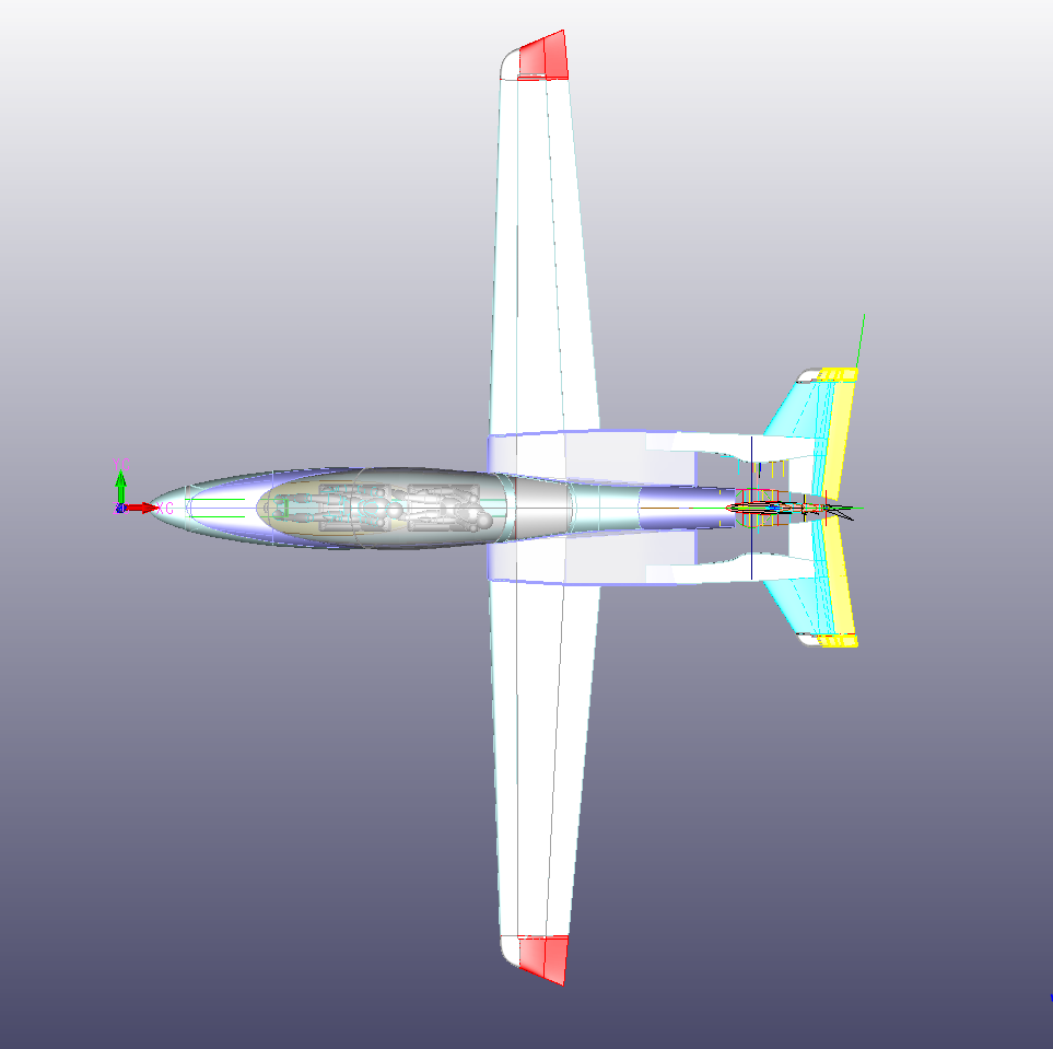
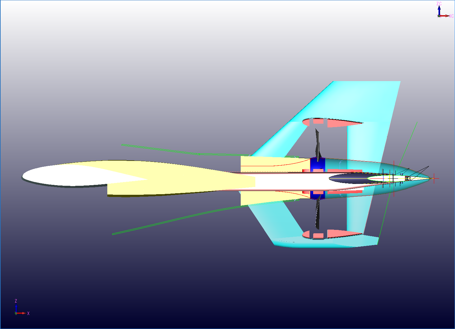
Take a look at Jeff's plane in our two 3D CAD programs. There is a great level of interoperability between the two systems.
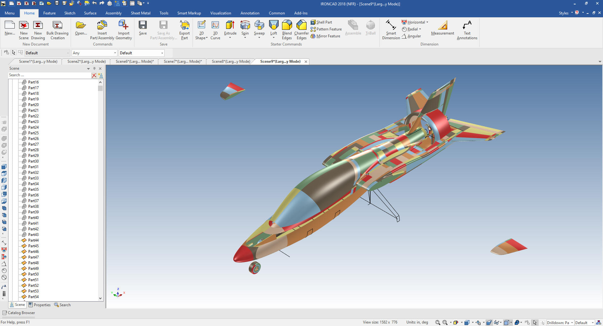
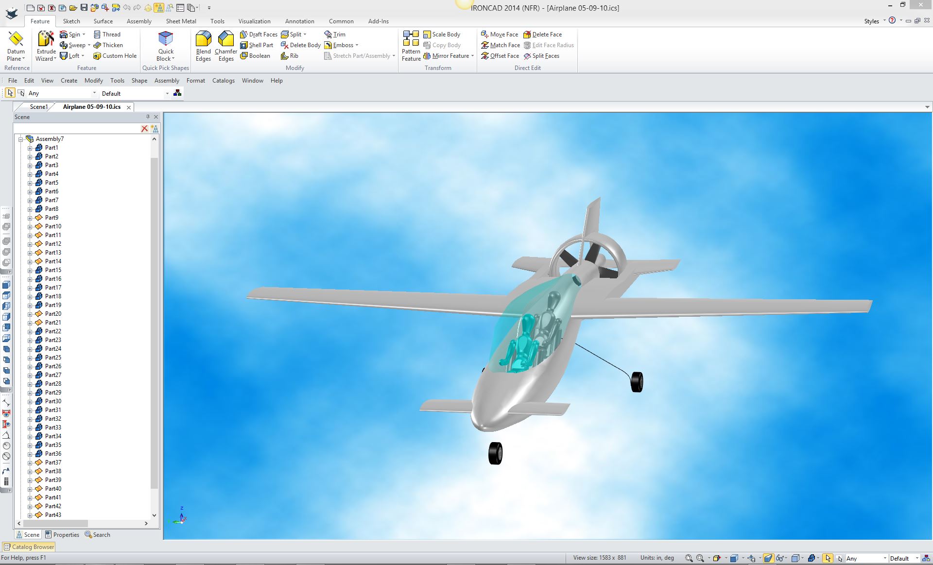
In IronCAD/INOVATE!!
Notice in the history tree, there are surfaces and solid parts making up the assembly. The assembly comes into one easily manageable file in both programs. Imagine not having to worry about your assemblies until you design is complete. It may even offer a new way of handling data management or PLM.
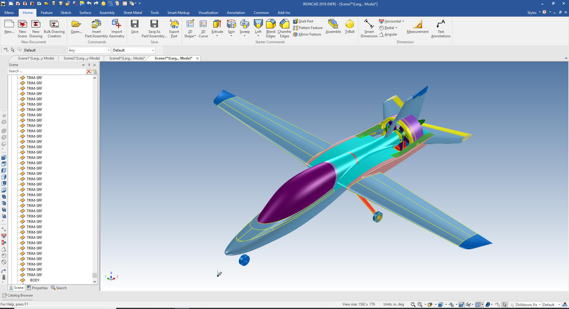
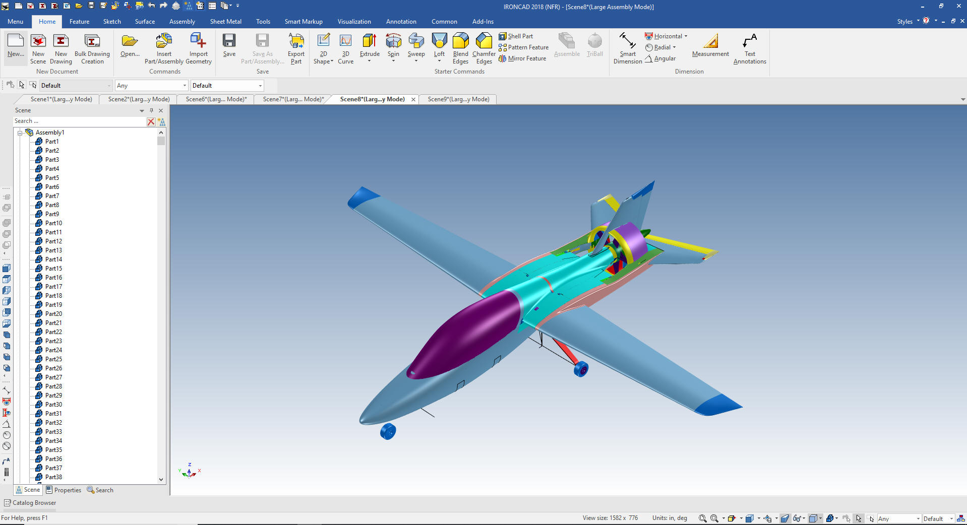
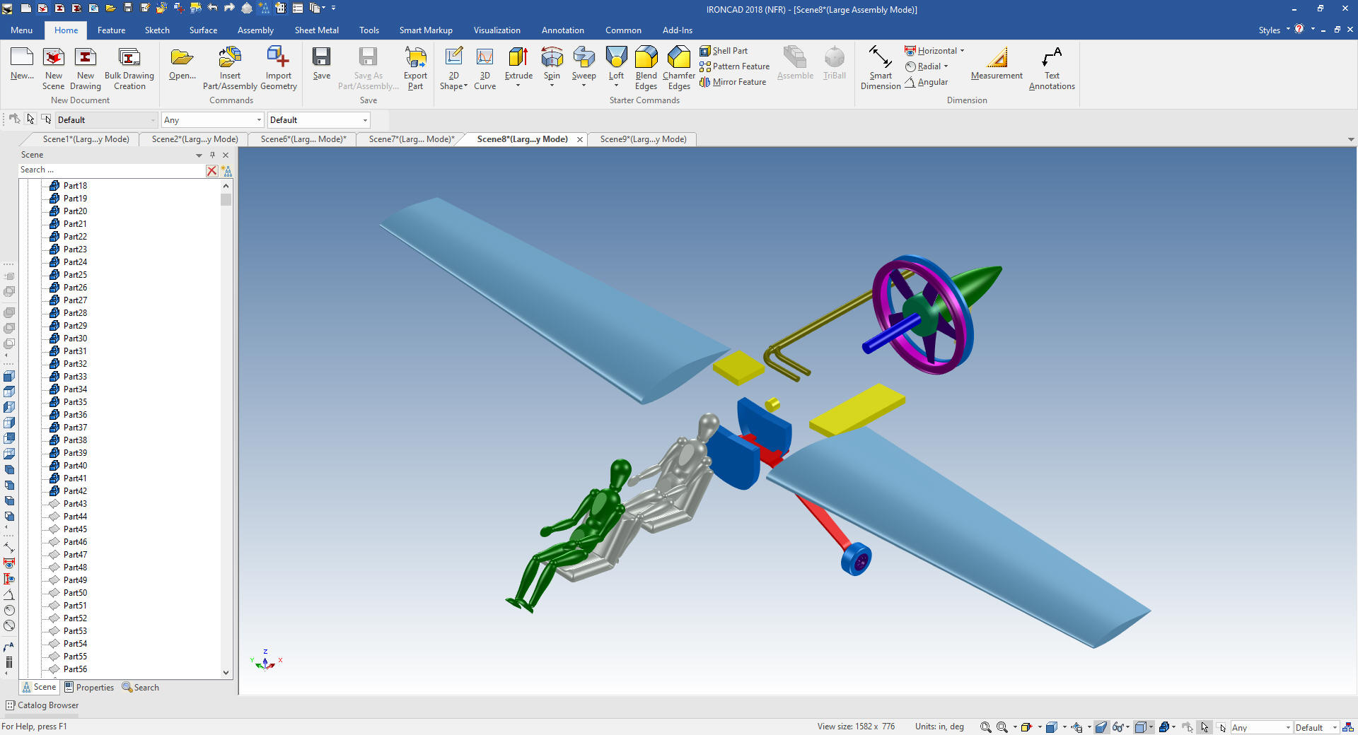
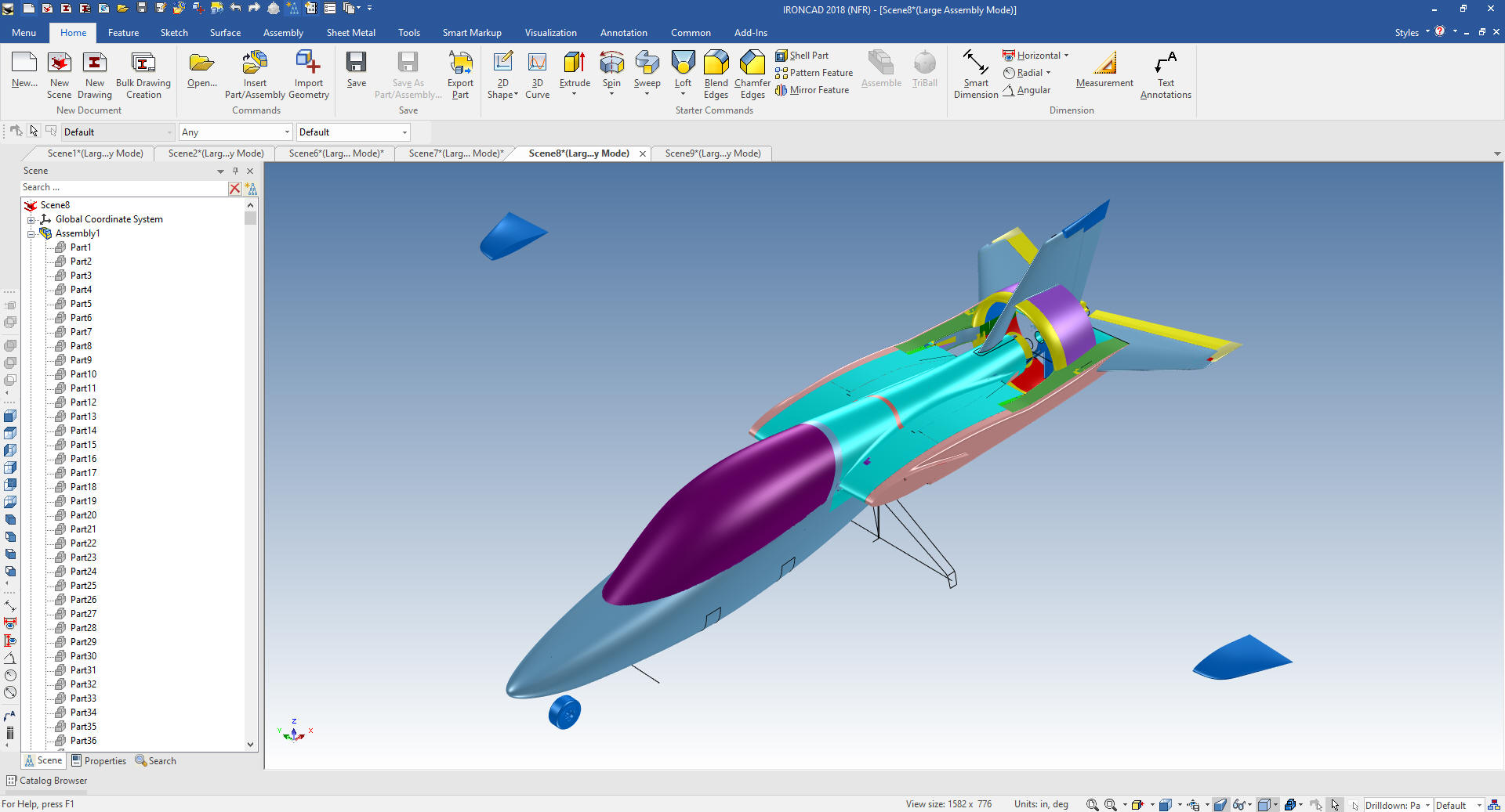
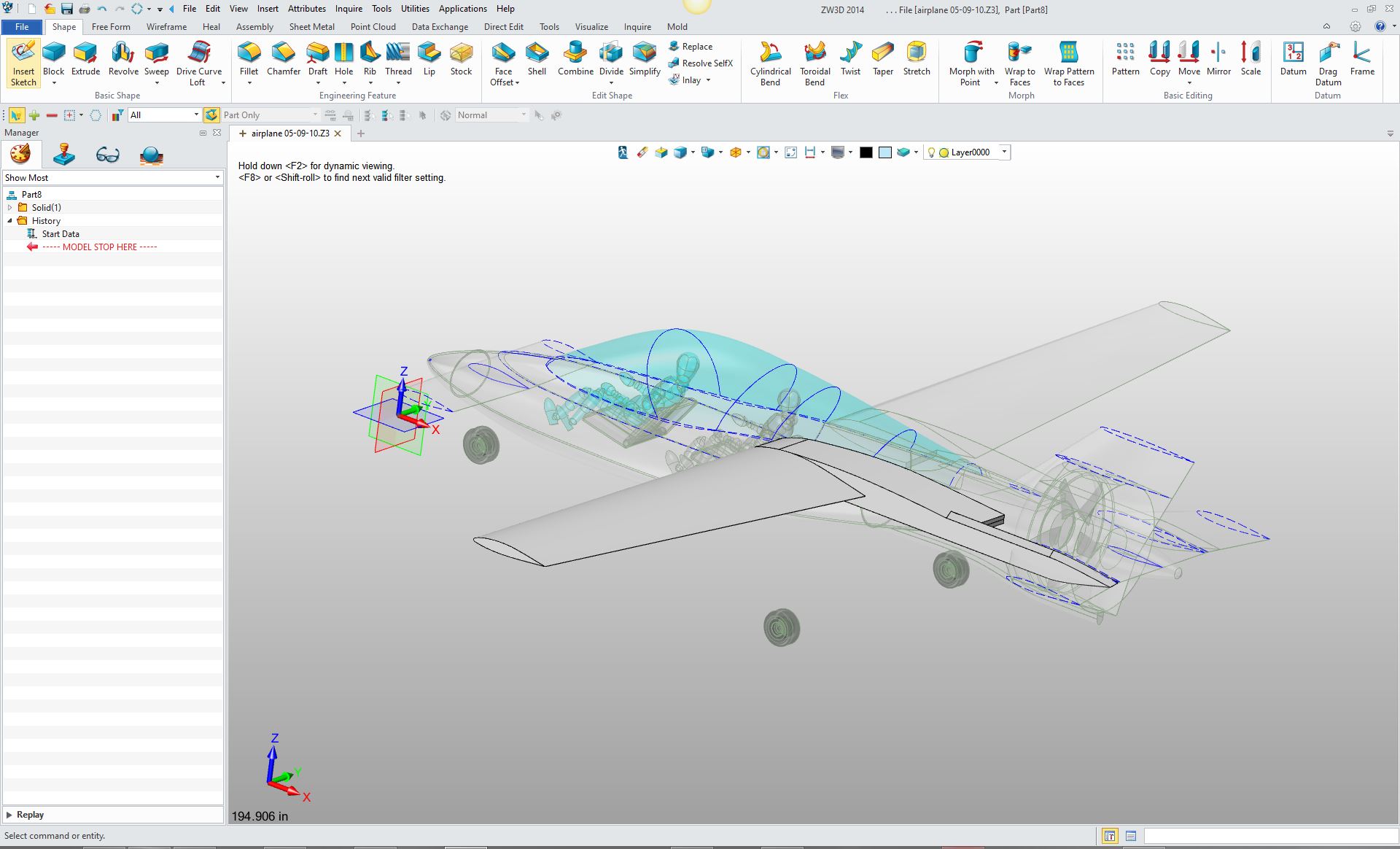
In ZW3D!!
This image shows that the wing assembly high lighted to be modified. It is a solid model and can be modified with the direct edit functionality of both programs. ZW3D has a high level of Hybrid modeling offering robust advanced surface modeling supported by 2D/3D wire frame design.
TECH-NET Engineering Services!
We sell and
support IronCAD and ZW3D Products and
provide engineering
services throughout the USA and Canada!
Why TECH-NET Sells
IronCAD and ZW3D
If you are interested in adding professional
hybrid modeling capabilities or looking for a new solution to
increase your productivity, take some time to download a fully
functional 30 day evaluation and play with these packages. Feel free
to give me a call if you have any questions or would like an on-line
presentation.
|