Educating the New Millennial 3D CAD Engineer | |||||
|
This article only focuses on the Industrial/Mechanical Engineer and the other industries that are associated, i.e, Industrial Design, Product Design or others that produce usable 3D CAD models and documentation.
As you can see below the engineer is now required to provide the engineering documentation. I have recently realized there is no training available for today's engineering documentation. With the elimination of the drafting group this mentored based system is disappearing or has disappeared altogether. Engineering Documentation is not on the engineering schools radar. In fact companies like Boeing have implemented the bizarre PMI that was introduced by PLM and MBE. Its application is basically defined on the fly. One of my associates, working at a large aerospace firm, explained to the engineering manager that the documentation was not to the company standards. His answer "Standards are only guidelines." My associate was shocked knowing that standards are the implementation of proven processes. The following article shows the lack of thought that goes into a PMI from a large aircraft firm. They are all their own. Ref: PMI vs AID Standards were the basis of all engineering design and documentation. Today, there is no standard engineering documentation training readily available. Update 10-03-15 Here is a job posting I received "A bachelor of science or higher degree in mechanical engineering, material science engineering, or equivalent, is required. A minimum of seven years of experience in mechanical engineering for complex systems, including design, development, integration, and test is required. "Experience in mechanical engineering development standards and techniques, including geometric dimensioning and tolerancing; with electro-mechanical components/systems, configuration management, and computer aided design (CAD) systems; and performing reverse engineering are desired." "Experience in metal failure analysis and material condition issues, e.g., corrosion, changes in properties due to heating, including preventive/corrective treatments/coatings, is a plus. U.S. Navy submarine/underwater vehicle experience a plus. U.S. citizenship and eligibility for a security clearance required; current clearance a plus." One question: Where does the engineering student learn those skills? I can tell you "No one could afford this guy"!! Updated 12-31-18 Or this guy Ref: Engineering Yesterday & Today Engineer's Job Description The Search for the Purple Squirrel Educating the New Millennial 3D CAD Engineer Today, it all starts with 3D Part Design 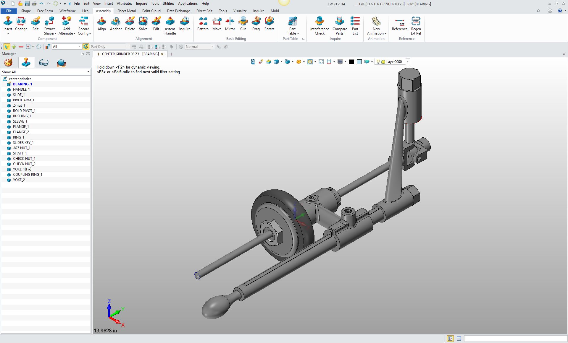 In the past we started with a piece of paper, a pencil and a drawing board. We would draw engineering design layouts. This is where all of the design was worked out. This was done by a board engineer or a design draftsman. Yesterday, it all started with Drafting This is what was called a detailed assembly! 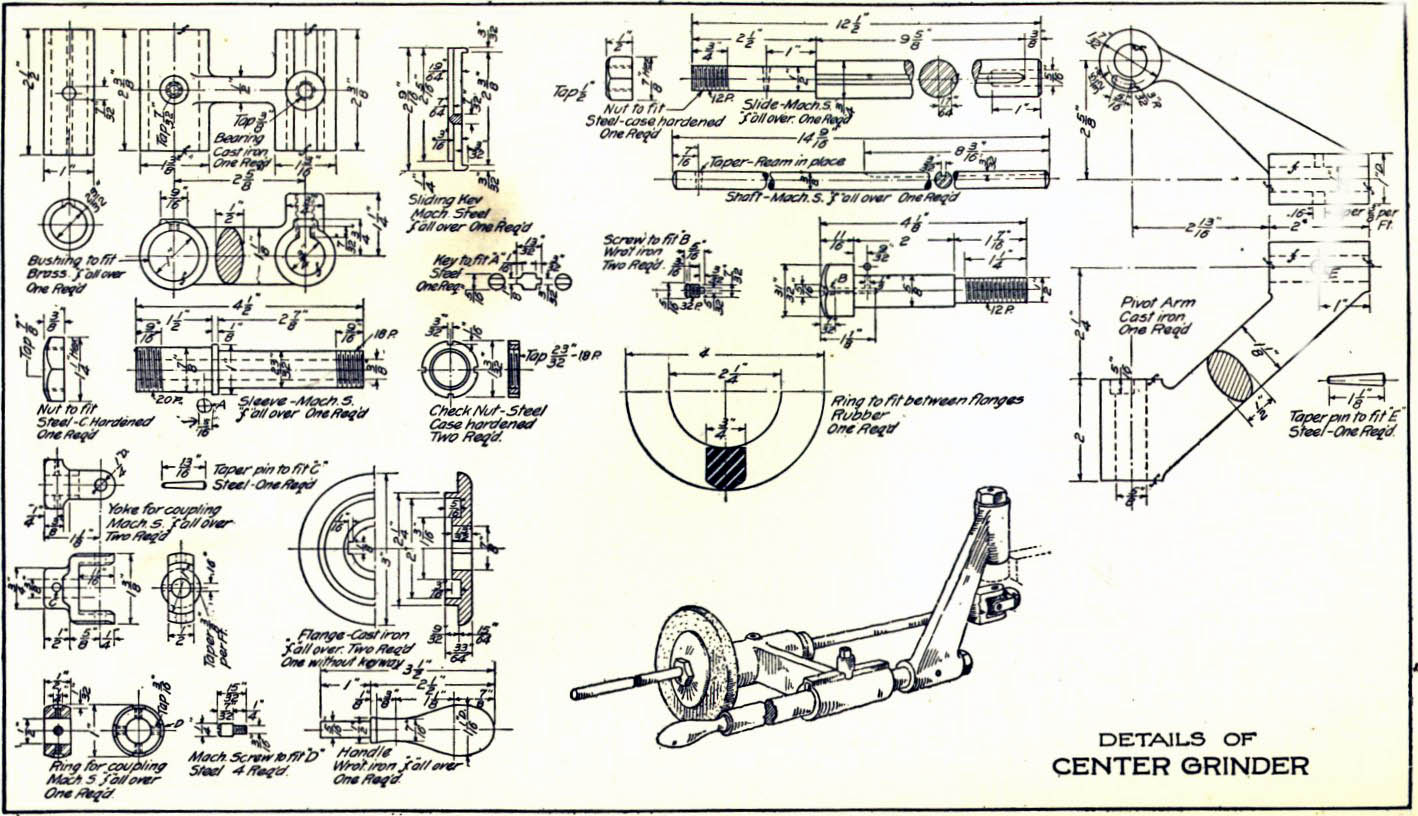 The parts and assemblies would be developed further with form, fit and function design making sure that it could be manufactured with the best and most cost effective processes. The drawing would go to the Checker (a senior draftsman) and be thoroughly checked. The checking was not only checking the drawing standard but the form, fit and function of the design, basically, making sure the part or assembly could be made and fit together. The drawing would be reviewed by the lead engineer then sent to the manufacturing, stress and material engineers for approval and then to the engineering supervisor for final sign off. Then the Engineering Documentation was Released Then the engineering package would be sent to Document Control for release. Which included documenting the drawings, getting blue prints made and storing the original drawings in the vault (Yes, it was a fire proof vault). They would then release the blue prints out to the different blue print centers, where purchasing and any other interested departments would have easy access to them. Update: 12-24-15 As I read through the above paragraph. I wondered how the other departments now accesses engineering documentation. I am sure it is not as easy as walking up to a blue print counter, ask for the drawing or looking through a file of microfiche cards and get a print. Are there terminals through out the plant where you type in the part or assembly number? What do you print out now that may only be in a 3D format? Do you have to have a tablet when you go to the airplane to review a problem? I can feel a new article coming!!! Ref: Engineering Documentation Today!
Enter the Engineer
The young engineer would come into Boeing and be put on the board for a year or so and work under the guidance of the Drafting Group. He/she would learn how to make drawings and get familiar with all of the incredible Boeing design standards. This was quite a surprise for most young engineers!!
Here is a story that makes this a bit clearer.
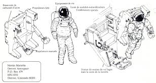 I was a contract engineer at Martin Marietta in the Denver area. Contract engineers were mostly composed of senior design draftsman that moved from job to job. Rarely did you find the degreed engineer in this field. Degreed engineers came in mostly as stress or specialty engineers. Most of the engineers on the job were direct employees where they were more stable to manage the projects.
We had a crew of young newbie engineers. They, like at Boeing, were put on the board as draftsman. But these young engineers had no drafting experience. I am not sure how I ended up with them. As I would help them they would complain about having only one class of drafting in school if any at all. They felt very inadequate to do the job. But, slowly, I would check their drawings and go over every error. This was time consuming, but Martin knew this. They were excited about learning, knowing that this was the beginning of their new career. We were preparing the next generation of engineers. I was the lead designer and the checker. Okay, that was how a young engineer "was" introduced to language of standard engineering documentation. Enter 3D CAD I was introduced to Computervision CADDS 4 3D CAD system while on contract with Williams International in Walled Lake, MI (Fondly known as Willy’s rocket shop) in 1982. I had 17 years on the board and was given the opportunity to train on the 3D CAD system after work. After a couple of weeks of training in the evening they brought me on as a "3D CAD Designer". Below is what it looked like when you designed in CADDS 4 green wire frame graphics on a black background with no hidden line removal. We designed for the next 13 or so years this way. With PC based 3D CADKEY color was added which helped immensely. I will never forget the first time we had real time hidden line removal with the entry of solid modeling, it was truly magical. Are you looking up or down at the part? 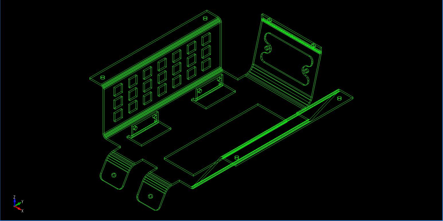 A new form of engineering documentation was created:
We designed in 3D. There was no more confusion about drawings and design. Now draftsmen would design by creating the 3D wire frame parts and then create the drawings from the 3D model. But these were not drawings. We created the views in a documentation module and just detailed (added dimensions and annotation) the parts. We did not create drawings! We now created what I have coined the "AID" (Associated Information Document) what the Boeing draftsman called the "Flat File". That was the last of my drawing days except for a short board job at Boeing where I was introduced to PC based 3D CADKEY. In the beginning 3D CAD was completely in the realm of the draftsman. Ref: To Draw or Not to Draw?? 3D CAD was quickly being implemented into the industry. While on contract at Boeing in 1986 I was introduced to PC based 3D CADKEY. Boeing was using 3D Catia 2 at the time. Soon CADKEY was in every group. All of the large industries adopted 3D CAD and completely missed the electronic drawings bullet. I have never made a scratch drawing in CAD. There were a few high-end electronic drawing packages but they never became mainstream. Where was Autocad, you ask? It really was an architectural program and pretty much useless as a mechanical design package. It had no copy protection and many companies moved from board drawings to electronic drawings. CADKEY had a dongle and was $3,500.00 so many opted for free Autocad. Ref: The 1980's - 3D CAD - The Beginning I started selling CADKEY to Boeing and all of the Boeing suppliers. We soon had a smooth operation of getting the 3D model as an IGES file plus a blueprint from Boeing. Hmm, the AIDs (drawings) were delivered as blueprints. There was no way of delivering a file such as a PDF. Surprisingly the PDF didn’t show up until the late 1990's. That may have been the problem with Boeing and the drawing. I am sure the PDF for Catia 5 was not introduced until at least 2000 if at all. Ref: Redefining 2D/3D Ref: CADKEY or Catia? Boeing’s Billion-Dollar 3D CAD Mistake! Catia 5 showed up on a PC in 1998 and introduced PLM (Product Lifecycle Management) and MBE (Model Based Enterprise) to manage the engineering process that replaced the AID (drawing) with the 3D model as the authorizing document. Now that they did not need drawings, Boeing decided they did not need the drafting group. Boeing slowly started moving the engineers to the 3D CAD system to do design. I am sure the engineers didn't realize what the future was going to hold for them. Ref: Can the 3D Model Be Used as the Design Authority? The drawings or AIDs, if done at all, are now being done at the end of the design and not utilized in the design. I actually use the drafting module in in my design process. It is much easier to work with an associated cross section as a separate view as compared to the slicing of the part in 3D. Ref: The Death of the Drawing Now with the drafting group gone and Boeing allowing the draftsman (now called engineering techs) to leave by attrition. A new engineer was created at Boeing: "The Millennial 3D CAD Engineer" I have an old jobshopper friend that is non-degreed, in fact, I introduced him to CADKEY while at Boeing in 1986. He got me a huge CADKEY sale at Enstrom Helicopter. He is now having a hard time getting a job. He has loads of Catia 5 and aircraft design experience, but the companies are now requiring a degree. Ref: The Death of the Draftsman 3D CAD is now the Tool of the Degreed Design Engineer Educating the New 3D CAD Engineer -2015  So as you can see in the history above, the mechanical/industrial engineer will soon be responsible for the complete design process incorporating all of the draftsman’s responsibility, from design to documentation. So as you can see in the history above, the mechanical/industrial engineer will soon be responsible for the complete design process incorporating all of the draftsman’s responsibility, from design to documentation. This is a new engineering discipline. What I call: The Millennial 3D CAD Engineer As I started to write this article I assumed training the new 3D CAD engineer would be very complicated. But I now realize it can be relatively simple. The engineer cannot come out of college and be thrown in a group of experienced draftsman anymore. Is he/she now thrown into a group of 3D CAD engineers that basically learned 3D CAD and form, fit and function design on the job. What will he/she need to know? Well first they will have to know 3D CAD. Now we can only hope they will have a bit of 3D CAD knowledge. If they are thrown onto a Pro/e Clone, you can only imagine the confusion. They have to know 3D CAD. Training 3D CAD in the past was relatively easy. We were training experienced engineering personnel that knew how to design on the board, engineers or draftsman with a thorough knowledge of form, fit and function and actually could read a drawing. It was a very easy transition. The new engineer will have to be familiar with form, fit and function design. Ref: All you want to know about 3D CAD training! The Training Program 3D CAD is the perfect engineering training tool. Today we "have" to include form, fit and function design as we train the 3D CAD system. I would assume the first year of engineering will have to include both 3D CAD training and form, fit and function design. Form, fit and function design is a natural part of 3D CAD training as we learn the different shape creation functions.
Ref: Learning Mechanical 3D CAD So it will be integrated training, killing two birds with one stone. We just give the engineering student a set of industry relevant "drawings" to create the 3D models. From a gradient of simple to complex, they will not only learn how to create 3D models but to understand the intend of the design presented in the drawings. This would introduce them to all of the engineering standards necessary to become good designers. Ref: All You Wanted to Know About Drawing to 3D Conversions Yes, this is drafting training. I would also include precision detailing (Applying dimensions in a precise way as to define the intent with or without GD&T) training. We would give them existing 3D models to detail. The engineer is going to be responsible for creating, checking and releasing the documentation and all changes and the maintenance and recording of those changes. It is a very standard process and should be included in this first year. They have to have a rudimentary understanding of these subjects.  Maybe even a bit of manual drafting to get the basic history of engineering documentation and familiar with the drafting tools of the past. Many of the tools defined the design process, like hole and other templates, even scales (engineering rulers, LOL). Maybe even a bit of manual drafting to get the basic history of engineering documentation and familiar with the drafting tools of the past. Many of the tools defined the design process, like hole and other templates, even scales (engineering rulers, LOL).Once they get this skill you then can start with the classic engineering training and with 3D CAD it will be so much easier. All of the theory would be done on the 3D CAD system with CAE for analysis and simulation. What would be coming out of college would be skilled 3D CAD design engineers. They will then have a smooth transition into engineering process. Very little training would be required on the job, at least for the basics. All new projects are a new learning process. Yes the 3D CAD systems are different but there is a movement to make 3D CAD much more standardized. Soon it will not matter what CAD system is used. So there you go. It is relatively easy. The 3D CAD system frees them to do and know so much more. I remember using trigonometry to create the absolute locations, now 3D CAD does it all. I would look forward to this type of training. No more will the engineer show up having to learn the basics on the job. He can hit the ground running. This could be a new day. Where do you get the instructors? So, Colleges, wake up. There are quite a few old manual and CAD design draftsman out there with an abundance of 3D CAD, form, fit and function and drafting knowledge just waiting to be tapped. They can be used to handle this transition until the process is in place. Where do you get the 3D CAD? Most of the popular CAD systems offer free systems to colleges, both of my products, IronCAD and ZW3D have this option. If you are interested give me a call and I will put you in contact with the company representative. You will walk in the door, sit down at a computer and start working with a very short learning curve. You will be hired for your engineering knowledge not your "3D CAD" experience. This may open the door to more telecommuting. Ref: All About Telecommuting Yes, this will upset today's 3D CAD Vendor controlled environment. It will eliminate most of the vendors that can not fit into the process there by hugely reducing the cost of engineering. Engineering will be put back in the hands of engineers. Engineering will again be in control. Document control can be moved to an admin process outside engineering, supporting the engineer leaving him/her to practice their profession. Designing the new products that may change our world. Ref: Standard Cloud Based Engineering Document Control Ref: Ref: The Worst to Best 3D CAD System and Why Oh, Oh! Not all is Rosy Sadly there is a bit of a dark cloud on this process. The draftsman was a worker bee with very little path to management. This will be the same with the Millennial 3D CAD engineer. He/she will be put in a position with very little chance of moving to management. They will be, like the draftsman, put in categories. Starting with an "E" level 3D CAD engineer up to an "A" level 3D CAD engineer. There will be the Checker 3D CAD engineer. Can you imagine the hierarchy that will develop? You will be supervised by the Lead 3D CAD engineer. But there will be very few opportunities to move into upper management since there will be thousands of 3D CAD engineers and very few management positions. Ref: Engineering Technologist? Engineering Technician? I suppose you will have to stay in school for a couple more years to become a: MS"3DC"ME The Master of Science "3D CAD" Management Engineer!! We sell and support IronCAD and ZW3D Products and provide engineering services throughout the USA and Canada!
If you are interested in adding professional hybrid modeling capabilities or looking for a new solution to increase your productivity, take some time to download a fully functional 30 day evaluation and play with these packages. Feel free to give me a call if you have any questions or would like an on-line presentation. For more information or to download IronCAD or ZW3D Joe Brouwer 206-842-0360 |


TECH-NET ASSOCIATES | RENDERING OF THE MONTH | CAD•CAM SERVICES
HARDWARE | TECH TIPS | EMPLOYMENT | CONTACT