|
The Space Between Engineering and Manufacturing | |
 The Purpose is to Make Things
“The Millennial Engineer is twice removed from the
I wrote the article below a while ago. As I pondered on this problem I
thought I would show how the engineering documentation gets to manufacturing. Engineering documentation is released to a document control archive. If the manufacturing is done in house there is direct access to these archives. This makes any problems with the design easier to handle.
So what Documentation did Engineering make available to Manufacturing? Pre-CAD we delivered drawings. A drawing included everything manufacturing needed to make the part. There were no other documents except references to the relevant industry standards. They were checked and signed off by engineering (designer, draftsman, checker, specialty engineers, lead engineer and supervisor).
The drawing package would be released to Document
Control, which would create blueprints and deliver them to the appropriate
departments and blueprint counters where they were archived and readily available to all. Standard Cloud Based Engineering Document Control
Manufacturing planning
would access the archives and get the documentation and deliver the specific requirements to
purchasing to proceed to
get quotes from the relevant supplier. They would mail the quote package or
have the supplier stop by. Rarely did the supplier meet with engineering.
The parts were quoted and scheduled for delivery. Like I said everything
they needed was on the drawing. If they had to come back for clarity, the
process was not designed for it and the lead engineer would face some
serious questions. The engineer was "not" involved in the release of the engineering drawing package. That was totally in the realm of the drafting group. The drafting group was responsible for the sign off, release and maintenance of all of the drawings. My First 17 Years or "How did we do it without 3D CAD!"
I had been a contract engineer for well over a decade
when I was introduced to 3D CAD.
It was Computervision CADDS 4
(Computer Automated Design and Drafting System). There was no CNC at the
time. These CAD systems were 3D wireframe and included a drafting module.
The selling point was they could make drawings faster by just
dimensioning instances of the 3D wireframe model. If you changed the part
all the views would change. This was a bit time consuming since you had to
actually blank, change line attributes and trim the object lines.
This was the end of drawings as we knew them. We
created what, I have coined, the AID (Associated Information Document). But
at the time
they were still plotted and treated like a drawing. The 3D wireframe model
was more or less useless for anything else. I think it was around 1987 that
I noticed that they were using IGES to translate the model for what was called 2.5 axis CNC. I was introduced to PC Based 3D CADKEY in 1986 while
on contract at Boeing. We were working with Catia 3 exchanging the 3D
wireframe models
by IGES. The engineering documentation was plotted on large plotters and
delivered as prints. They were storing the files in a HP plot format. In the
late 1980’s surfacing and solids showed up along with 3 axis CNC. By the mid
1990’s we were delivering the 3D model and the prints.
It wasn’t until the late 1990’s the PDF showed up and we could deliver the 3D model and a PDF as an email. Many purchased Acrobat or a Acrobat clone and were
instantly creating the PDF documentation. The mid-range 3D system started
including direct PDF creation in their systems. The high end systems always
seemed so far behind them and still are. By 2000 all of the major 3D
CAD systems
were on the PC. But at the same time the PDF was made available
Boeing was moving to Catia 5 and were incorporating the MBD (Model Based
Definition) PMI (Product Manufacturing Information) format. I am not sure
this decision was because they were still delivering the prints and the PDF
technology was just becoming widely available and they were not aware of it.
But the prints were costly and they thought PMI would solve the problem. In the beginning the PMI included most of the dimensions, but it was soon realized that it was just to cluttered and time consuming to use it.
The decision was made to only put the basic
dimensions and cover the other dimension with profile feature control. This
was even too cluttered and it became more minimized where only the limited dimensions are now included
with complete GD&T.
I had sold virtually every Boeing
supplier a seat of CADKEY to interface with Catia 3 and 4. When they moved
to Catia 5 an implemented this MBD PMI solution they were delivering native
files forcing the suppliers to purchase a seat of Catia 5 or a current
compatible seat of Enovia to view these PMI. This threw the suppliers into a
tizzy. They didn’t know what to do. Many of the programs could import the native Catia 5 file but there was no way to view the PMI. PMI is not a standard, it is a native format used inside the CAD system. It is delivered as a native CAD file. This is very problematic. You have to have each of the CAD systems, a specific CAD supplied viewer or a 3rd party importer. As you can see this is a can of worms trying to keep 3 or 4 systems native PMI files current. This is a big problem for those suppliers that work with large companies that have implemented this system.
The MBD and PMI is incredibly costly
and convoluted. It takes a complete PLM system to manage. That includes a
staff of InfoTech folks and expensive module in the native CAD system or
expensive 3rd party PLM solutions. All complicated and requiring
expert training. The
The Worst to Best 3D MCAD Systems Expanded! The smaller companies cannot afford these high-end CAD systems. They use the more cost effective mid ranged systems.
They create fully detailed AIDs (drawings) as PDF and deliver it with the 3D model
in a neutral (STEP) or native file.
There is very little complication. The CAD/CAM systems the suppliers use can
read most of the native files of the popular systems plus all of the neutral
formats and with the free adobe reader they can view the documentation. No
special equipment or software required. Can you imagine the additional costs
the large companies that have incurred by basing their complete operation on
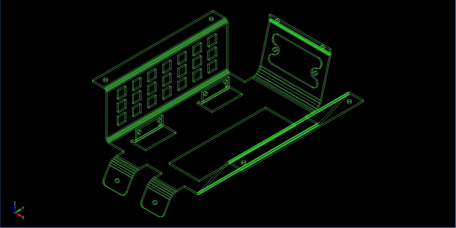
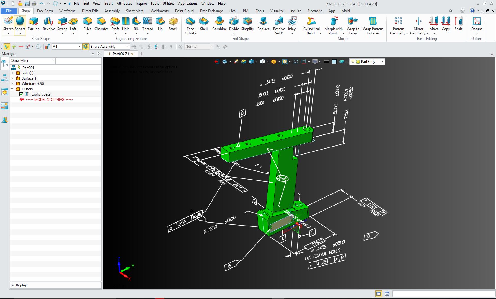
the PLM included in a high end CAD package? It is truly shocking. This article shows an actual released PMI (shown above) from a large aircraft company. It violate so many standards of the past. It is like someone with virtually no engineering experience did it. I can send you the original Catia file, if you can even read it. This is a sample file for their suppliers. It is incredibly embarrassing. PMI vs. AID (Associated
Information Document)
When a designer creates a completely
detailed AID it serves as a second check on the design for errors or a
better design. It is a format that is easily reviewed and checked. As
compared to the PMI, that today just requires the minimum limited dimensions
and GD&T plus a seat of the native software. If you look above, you can see
how the PMI looks. Here is a comment from a BSME PE forced to use MBE and PMI. "The big problem is, any failure will be blamed on the responsible engineers and not an unworkable system. MBE is already being backstopped by drawings in many organizations that are forced to use MBE, but the drawings are frequently not in the release control process because they are not the "primary" data driving fabrication. A fine mess.." Trust me the smart companies are creating completely detailed AIDs (drawings) to be delivered as a PDF with the 3D model. The cost savings can not be denied! This PMI information with the other required
information is adequate for manufacturing to create the parts. But this is
where engineering documentation seems to becoming inadequately defined.
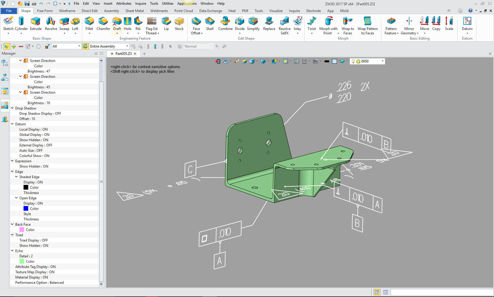
Manufacturing is now having to go back to the companies to get clarity as
described in this statistic. Sadly, this is becoming a normal process. This was
"NEVER" an accepted practice in the past.
So what has eliminating
complete detailed AIDs (drawings) accomplished? It has not streamlined engineering, it has made the
documentation less defined, the document control much more convoluted,
access to the information requires special software, demanding a complicated
application of dimensions and annotation in a non-user friendly 3D environment and
making review and checking of the documentation virtually impossible. The PLM folks are now trying to bring their
complicated process to manufacturing. Here is the space that they are trying fill in a
nutshell
We do not want to get into engineering changes here. The problem with engineering to manufacturing is the InfoTech industry of which the high end CAD companies have now put in charge with their complex PLM systems. The funny thing is they "think" they actually know something. PLM and the
Infotech world work top down, Dassault more than likely told Boeing
they could do the engineering, PDM and document control. Can you imagine a company that has been building airplanes without CAD for 70 years listening to a company with unproven technology to make such promises? Then actually put them in charge. They could automate everything. All parts would be
associated to the assemblies. Everything could be easily accessed with PDM
and PLM. Nothing could be further from the truth.
Engineering is very simple. It is not a living
body of data. The truth is, the faster the data dies (moved to archive) the
better. Once manufacturing uses the engineering documentation for CNC,
tooling or other planning the engineering is never accessed again. When the
product is delivered all parts and assemblies should be put into one file.
Like a refrigerator, once built the engineering is put away. Yes, it may be
used for the basis of new products, but that product is done.
It doesn’t have to be associated except maybe in the
beginning of the design, even if it matters then. The documentation should
have the used on information and the assemblies still have a parts list. All
parts have part numbers. Simple search program should be all that is
necessary to find a part. Hell, we could go to the blue print counter or
microfiche to find them. Assemblies are all in one part number. The Embedded Title Block! A PLM Solution! But this concept completely escapes the data only
focused IntoTech professional and the millennial engineers seem to have no idea. This
was a fact that was well known by only the draftsman and board engineers.
Sadly, with the introduction of 3D CAD, soon the draftsman was not needed
anymore and their responsibilities were given without any transitional
preparation to the 3D CAD engineer.
Can you image a process that was standardized and totally controlled by one profession slowly disappearing? All applicable knowledge has also disappeared and now engineering is trying reinvent the wheel, even though the wheel is sitting right in front of them with the drawing archives of the past. Boeing InfoTechs wanted drafting gone so badly that it renamed draftsman, engineering technicians, a horrible misnomer. The draftsman, knowing the supreme importance of documenation was the enemy of BCS (Boeing Computer Service), now the InfoTechs! Drafting lost! Engineering Technologist? Engineering Technician? CONCLUSION So will engineering get its ducks in a
row enough to realize how simple the process is? I truly think that engineering has become overly
digitized to the point it is costing more than the manual process it has
attempted to replace. We used to have drafting, engineering and document control all
working in an industry based standard process. Today, just the myriad of 3D CAD systems virtually
making standardization impossible. Then add the incredibly unworkable PLM
and MBD document management efforts. I have said this before, there is just
not enough applicable knowledge and too much vested interests to bring a
cost effective standard back to engineering.
Manufacturing has escaped this
onslaught of amateurs. They basically work around any of the requirements
that are coming out of engineering today. WHY? They are not based on academic
or CAD vendor based management. There are no "know it all" PHDs, MSMEs and InfoTechs getting in
the way. Most are hands-on professionals that have to get the parts
delivered or they don’t get paid. Very A to B.
This is where the rubber meets the road. Engineering needs to take charge of the process and
put the 3D CAD companies and InfoTechs back in a subservient role where they
belong. The Purpose is to Make Things that Work!
|