|
Embedded Title Block &
This article was previously call the "The Ultimate Part Mark", but as I was explaining this concept on one of my discussions on Linkedin and one of the fellows said this was basically an embedded title block. That expressed my idea much better. So here is The Embedded Title Block! This information was included in Redefining 2D/3D article. But I thought it would be a great stand alone article. Today the industry is attempting to use complex PLM and PDM solutions to handle our "Document" management problem. They are trying to replace one simple document, "The Drawing", as the only authority. The drawing carried all the information necessary to create the part. You sent a print to the suppliers, illustrators, purchasing, invoicing, virtually ever department in the company could easily use these documents.Enter the 3D MODEL. Yes we all know we can take this model and load it into a CNC program like ZW3D CNC and create a set of instructions to drive a mill to create the part. This started those in power, thinking, "We really don't need drawings to get this part made." It was a good idea, but a bit short sighted. Unfortunately they did not think it through, they soon realized that they had to inspect the part. Enter PMI (Product Manufacturing Information) which dimensions the mating features including a minimized bastardized GD&T and other annotation in a 3D space. It really is a mess to follow. Now, of course, this is a special format coming out of the native CAD system and requires the native software or a special native or 3rd party viewing package. Take a look at this solution in Redefining 2D/3D.
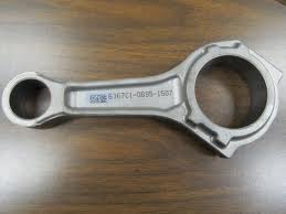
While the PMI may be viable for machined and sheet metal parts it completely fails with inseperable assemblies. In this articles is is a Catia PMI from a large aircraft company. It is a machined part with a couple of nutplates that are not called out, but referenced in what you could all "obscure notes". This shows that there is no standard and engineering is struggling to make it complete. An old jobshopper, like me, just chuckles at the blatant ignorance. You can see that the AID is much clearer and easier to review. PMI vs AID (Associated Information Document) Why MBE/MBD/PMI Will FAIL Part II This has become a horror show keep track of the parts. There is only a file number. Have you ever seen a VAULT of parts, just a list of part numbers no information, hoping the document management system is being kept up to date. Of course there is very little information in the file name. I suppose somewhat of a part number and revision and that is about it. No information on what changed. You would have to have an AID (Associated Information Document)(drawing) for that, but we have no AID (drawing) and the PMI doesn't seem to be the correct format to record this. So what we have is a potential for undocumented parts. Enter 3rd party Validation software. Oh Oh, the "Band-Aids" started showing up. Yes now a supplier has to invest in 3rd party software to assure that the model is correct. At approximately $5,000.00 you can compare apples to apples and get a report that the apples are apples. Now there is another less expensive bit of software that just compares the parts and shows you the differences. It is like getting two drawings one original and one updated, then sending it to a specialty group that finds the differences. Large companies spend millions on CAD software and now make their suppliers purchase software to find the revisions in the parts. If they don't have the revisions documented they have to treat the parts as a new job and reprogram them which is very time consuming and increases the price of the part. PMI is such a useless document that there are 3rd party quoting programs that allow you to basically add dimension for sizing the raw materials. I wonder how the MBE/PMI folks never even realized that this would be a problem. Quoting Tools: CAD Dimensioning Another Band-Aid for MBE/PMI! PLM has become the most incredibly complex data management system. You have to be a trained PLM specialist to even understand it. Yes, there are now PLM specialist required in a company to implement this system. Sadly it is tied to dated CAD software so there will never be a standard. Or will there?
The Worst to
Best CAD System and Why!
We need a standard. We have made a mess of PDM (Product Data Management) and PLM (Part Lifecycle Management). The drawing was the only source for part information and was a successful standard for hundreds of years. We have lost that but we can get it back? And is there a vested interest to stay with the current mess. So how do we do this without specialty software?
A Simpler Solution - The Ultimate Part Mark!
Most CAD package can create solid text and emboss or imprint the part name, number, revision, website and phone or contact information in a part. This virtually solves the problem. This really relates to large companies that utilize heavy use of outside suppliers, but could easily be a standard for all parts. We want to have only one part with no extraneous data so all CAD systems can read it as one part.
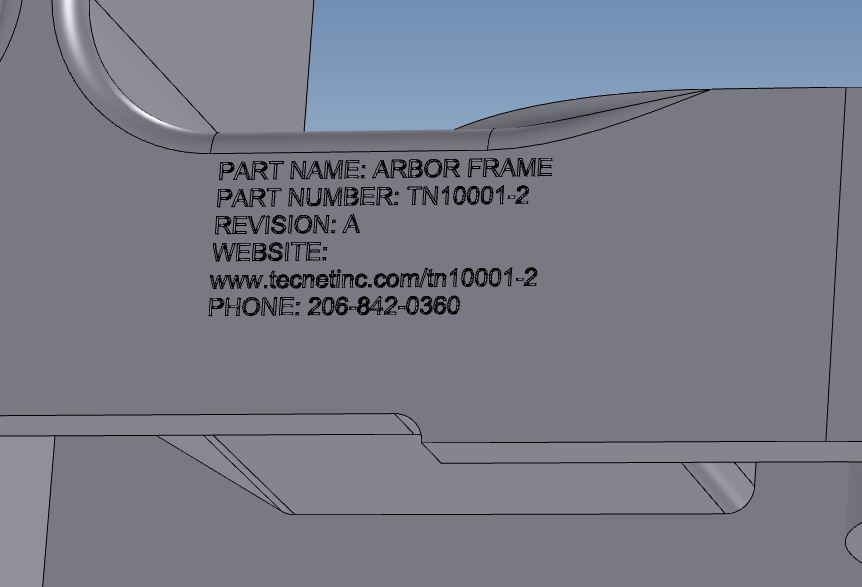
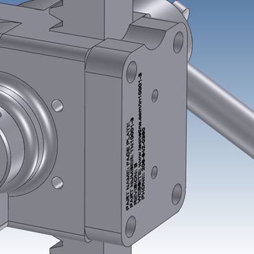
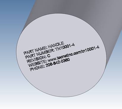
The Embedded Title Block Defined! Take a look at this concept. INOVATE is the tool I am using here but I am sure all of the major 3D CAD programs can do this. ZW3D is has the most flexible 3D text creation tools. It comes with enough pertinent information for anyone to make sure they have the latest version. Of course this is mostly for those companies that have many outside suppliers. The data could include the following and embossed or engraved in the part. Part Name: Since I started my engineering career at Boeing in 1965 as a draftsman. I know a bit about how the drawings were done and distributed. In the beginning we worked with blue prints. Yes actually they were white on blue. We had blue print counters throughout the plant. Then I left the industry and came back in 1977, now there were microfiche, we could now get all of our drawings on a card and print the parts lists. I could take hours and hours to research to find the correct configuration. But with the drawing being the authorizing document, it was always kept up today with ADCN (Advanced Drawing Change Notice) or an DCN (Drawing Change Notice). There was no doubt on which revision they had. I really am not sure how it is done today. But when the model gets translated to a neutral format any reference of the 3D model is lost.
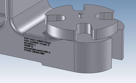
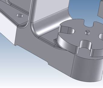
Here are a few examples of having a part mark on the part itself. You would put in on a easily modified surface. INOVATE makes this easy. You just drag the base text from the catalog, edit it, size it with handles and subtract or add. You can how the text can be sized below. Most CAD systems can modify the part to eliminate the part mark to have a clean machineable part. This is where a history based system has an edge on direct editing. You can just suppress the covering extrusion. With direct editing only products you have to have two parts. Luckily INOVATE has both History/Feature based and direct editing functionality integrated in the program.
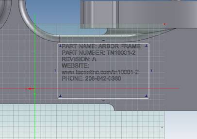
For assemblies you can have large separate part with the same information. Now, of course, we need to inform the suppliers that this is not part of the model and they have to fill it in or subtract it. The CAD products I use is IRONCAD/INOVATE or ZW3D. Both can equally do this job. Many of the CAM software packages can also do this.We really have to get over the model being the only authorizing document and can not be altered. Many times we will get a corrupt model and we have to work with it to work in our CAM systems. We need to also have an completely detailed (dimensioned) AID (drawing) to travel with it. This eliminated any confusion about the part. It also serves as a second check by the designer and a much better format to review, check and release. Many times the CNC programmer will alter the part to eliminate a feature for ease of machining. I sold direct edit CAD software for years to Boeing suppliers. Here is an article that shows this process. Checking, Design Review, Manufacturing and Data Extraction! Ultimate Document Control Years ago I envisioned a Web page for each part or assembly. This would be done by a document control group, outside of engineering. Utilizing the release package or bundle from engineering. This would be nothing more that modifying a template.Update: Onshape offers the below concept today. Onshape is by far the most exciting developments that has been introduced to the CAD industry. Today you can have a standard deliverable with the latest information directly accessible to other engineering personnel, purchasing, marketing, document control, manufacturing, tech pubs, etc. You could have non-engineering personnel maintaining this information, let engineers do their work. This webpage would only source for the part or assembly documentation. What the web page would include:
Would we include a drawing or AID? Of course, now that we have the web page as the only authority. We can easily have a PDF available for download for inspection purposes or clarity. At any level of detail even the failed PMI. Who would use this web page.
This is just too simple and surprising that no one has thought of either of these two systems. But there is more!! Let me introduce you to GrabCAD Workbench!
TECH-NET Engineering Services! We sell and support IronCAD and ZW3D Products and
If you are interested in adding professional hybrid modeling capabilities or looking for a new solution to increase your productivity, take some time to download a fully functional 30 day evaluation and play with these packages. Feel free to give me a call if you have any questions or would like an on-line presentation. For more information or to download IronCAD or ZW3D Joe Brouwer
|