Engineering Documentation
A Primer for
the PLM Guru!
This article relates only to the industrial/mechanical industry!
What is a PLM Guru?
Most of these guys are Infotech Specialist with
data management experience only, others have Mechanical Engineering
Degrees but have not spent any time as Mechanical engineers. These are
BSME, MSME and even PHD’s in engineering.
Let’s take a look at some of their qualifications. These
are the top PLM posters.
-
PHD Civil Engineering – Never even did any “Civil” engineering, software development only
-
BSME - not one day of engineering – Started at PTC
-
BS Aerospace – 4 years engineering – 13 years PLM! Nope, none in Aerospace!
-
Engineer’s Degree in Information Technology?? What does that even mean?
-
PHD Mechanical Engineering – Development of software only?
These are 5 fellows I have seen posting PLM
information.
Not one has ever been in the world of engineering
documentation.
This is a prime example of the gibberish that passes for PLM knowledge!!
Oleg seems to be the quintessential PLM Guru. He is all over Linkedin. I have discussed PLM with him a couple of years ago. I have been beating the drum that PLM will fail and now Oleg finally agrees.
Note: Oleg has disconnect from me on Linkedin. You cannot ask these folks too many logical questions before they get upset.
Oleg is a founder of OpenBOM. Now this was the first time I found that the PLM folks did not tie the BOM to a specific assembly. This program is basically a company part catalog. It seems to be a bit silly since they already have all the parts/assemblies documented and available. I describe the problem with the moniker "BOM" defining two confusing processes under Assembly Documentation. BOM is not even an industrial/mechanical engineering term.
I seem to be the only one that has any contrary view on PLM and MBE. But then the Millennial engineers have never worked in an effective engineering system and truly do not know any better. Engineering management is the least curious group, they just seem to accept anything!
Funny little aside it took me half an hour to
find out what PDT meant.
Product Data Technologies
These folks are nuts about "DATA" wasn't he a character on Star Trek?? LOL
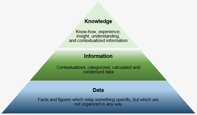
Sadly, the word "DATA" doesn't really work in engineering/manufacturing. Engineering runs on documents. What ever form it is: The drawing, the model/AID or the PMI.
"Engineering's only purpose is to make
available
concise, complete
and unambiguous documentation to manufacturing"
Engineering Documentation is the only thing that has to be managed.
Why has the engineering process strayed so far from the standard that was used for centuries? Because those that managed and maintained it were the drafting group. Sadly, there are no PHD's in drafting. This is always the result of trying to reinvent the wheel in a place where the wheel is very well defined. Product knowledge, proven standards and work force continuity is the formula for design success.
So what is this documentation?
These are totally separate operations.
The huge mistake the PLM Gurus make is they think everyone is talking to each other. Maybe in a very small manufacturing company and even then it shouldn't be necessary. If it is going on then the job may never get done.
The Digital Thread Myth
The PLM Gurus talk about a "Digital Thread". This is some sort digital hookup between engineering and manufacturing. I don't even know how they come up with this! Engineering and manufacturing operate on complete different schedules. Engineering delivers the released engineering documentation to an archive that is easily accessible, not only by manufacturing but many other departments, like research, materials, analysis, marketing, sales, etc. Engineering accesses this archive for errors and new design.
You could put it into these two terms:
Engineering is infinite and manufacturing is finite.
Engineering
There is no need for PLM. All information is within
engineering. Mostly residing inside the CAD system. Any
simulations or analysis is inside engineering. Data is moved
inside the system and maintained by each companies
engineering standard part/assembly document management
process.
This can be done on a napkin with a couple of entrepreneurs or by a formal presentation in a board room.
Configuration Management
Again depending on the size of the organization can be some informal requirements to one or more engineering groups.
Design
A staff of engineers and designers develop the product.
Documentation
I have said many time engineering's only purpose is concise, complete and unambiguous documentation. This is reviewed and checked and released to an easily accessible archive. There should be no need for engineering input after release.
Document Control
There is no need for PLM. The documentation no matter what format should be outside engineering and especially not in the CAD system. All engineering documentation should be archived and easily accessible in a standard format.
Released Documentation
The engineering deliverable or package is released to the document control group. They are mostly admin people that have a set process to release the documentation. They make it widely available in a format that is easily used. In the past it was the blue print, then microfiche and now with CAD in these three formats.
Today engineering documentation come in three formats.
1. The Drawing
This can be manually created or with an electronic drawing package such as Autocad. They are made up of separate non-associated orthographic views or a schematic, such as a floor plan. They will be released in the form of a PDF. PDF is the standard format for all drawings whether directly created from the CAD system or scanned from the original manual drawing.
Enter the 3D model
Today, the 3D model is used in a variety of ways. But in document control it is used as a pattern for CAM (CNC) or a variety of other manufacturing processes.
2. The Model/AID
3D model plus the AID (Associate Information Document). The AID is created from the 3D model in a documentation module in the 3D CAD package. In the beginning it replaced the drawing and was handled the same way. An original was printed on vellum or mylar and was used to create release prints it travels with the 3D model, hence, associated information document. Today, they are delivered as PDF. The AID can be generated from a part or an assembly.
3. The PMI
This by far is the most convoluted of engineering documentation. It was devised to solve the problem of delivering AID prints. This was introduced by MBE (Model Base Enterprise). Even though the AID, based on the model, was the only way to get documentation out of 3D CAD, someone thought that this was a new concept. "Model" became a buzz word.
Why MBE/MBD/PMI Will FAIL
The PMI is what you can only call a 3D AID. It has minimized GD&T (Geometric Dimension and Tolerancing). There is very little dimensioning going on. It has all of the annotation also included. The reason this will not become a standard is that it is based on the native CAD system. You need the native system to truly use it, including an integrated CAM systems.
While the PMI can be used for CNC and inspection it is worthless for fabrication and assemblies. It is not an engineering document, it should be considered a minimized manufacturing document.
Quoting Tools: CAD Dimensioning - Another Band-Aid for MBE!
Once you step out of the native CAD system many compatibility problems arise.
Can the 3D Model Be Used as the Design Authority?
In many companies the native 3D model is the design authority. Even though this is not being followed through they have demanded the suppliers to use a 3rd party validation program to assure that the 3D model is the same as the 3D model used for CNC. This gives a warm fuzzy feeling but is totally ineffective.
Compare and Validation Programs? Band-Aids for Self Inflicted Wounds!
I will make this bold statement.
The 3D model can "not" be used as the design authority!
Manufacturing
No need for PLM. Engineering is rarely involved unless the documentation has problems. If this happens, it becomes very costly with slipped schedules. It is very, very important the the documentation is correct, complete and unambiguous, no matter what format is delivered. Manufacturing does not concern itself with design, it only is concerned about making the parts and getting paid.
Engineering Documentation Today!
Part Production and delivery.
Manufacturing will take the release documentation and more than likely put it into another format. This will consist of tooling and CNC programming depending on the industry. The documentation will then be use for inspection. I do not consider inspection a separate function. This documentation will be archived within manufacturing.
Final Assembly
This is where responsible engineering may show up for first article. They will document the assembly and note any errors or design modifications. They may go back with a bit of modifications and do the complete cycle again with ADCN (Advanced Drawing Change Notice), DCN (Drawing Change Notice) or ECO (Engineering Change Orders). With the model being the authority they cannot just change a dimension as the did in the past they have to change the model directly and rerelease it. So it is a bit more timely process that can delay a project and also open the door to Murphy's mischief. It is interesting that many companies will not trust the supplier to make the changes. With the engineering based only on a drawing, changes were much faster.
The ADCN vs MBE
Engineering Ignorance Defined III
How to Define a 3D PMI Assembly
You have got to be Kidding
Today's engineering documentation comes in only three formats. I will define it more here.
1. The Drawing
This was the only format that was used Pre-CAD. Today, they are still being produced in a few industrial/mechanical companies using electronic drafting CAD (Computer Aided Drafting) packages such as Autocad and Draftsight. Mostly, fabrication houses that do not use machined or sheet metal parts. Many suppliers now demand 3D models.
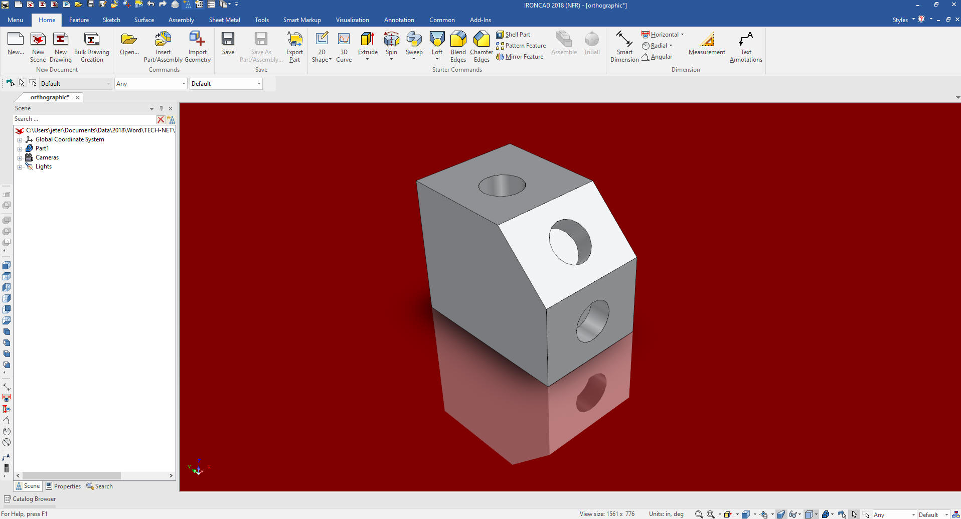
A drawing is made up of non-associated projected orthographic views. I am sure many of you PLM Guru's may not even know what that means. I will show you.
The part will start with a front view.
Project the Right Side View
Project the top view
Let's project an auxiliary view based on the diagonal face.
These drawings were made up of lines, circles, arcs and splines. Each entity was drawn separately and the views were projected using light construction lines that were erased later. We drew by sliding triangles, T-Squares, drafting machines, compasses, a variety of templates and French curves.
Today they use electronic drafting packages like Autocad to do what we call "Scratch Drawings". These are very time consuming and are prone to error.
2. The AID (Associated Information Documentation)
Does anyone wonder why the industrial/mechanical industry went to 3D?
I can hear you now, Uh, for CNC? Nope, that didn't show up until the late 1980's. Hmmm, Ah, 3D printing? Nope, not until the late 1990's. Wow... Yes, realistic rendering and animation!!! Nope, not until solid modeling showed up.
Well why then?
Faster drawings!
Yes, in 1982 I was introduced to Computervision CADDS 4.
CADDS - Computervision Automated Design and Drafting System
3D CAD was in the realm of the draftsman for decades.
The Death of the Draftsman or “Where has all the talent gone?”
Yes, these were sold as faster drafting systems. Computervision sold for $250,000 per seat with a minimum purchase of three seats. Scratch drafting as shown above was a bottleneck and Computervision must have has some great data that going to 3D design was a cost savings solution. Mostly Aerospace and plastics were the first to introduce it.
They were 3D wire frame and the only use for the graphics were to generate documents. Why did I say documents? Because these were not drawings. Sadly, they would be printed on vellum and used the same as scratch drawings. Thus, they were still call drawings and released as "Prints".
Boeing draftsman coined them the "Flatfile" as compared to the 3D file.
I have coined them the AID (Associated Information document) now that they provide reference, manufacturing and inspection information for the 3D model.
This has caused a huge confusion in the industry. The name for any drawing like document is the "2D drawing". This is so stupid, what other kind of drawings are there?
The Death of the Drawing
Well, an AID is not a "2D drawing".
It is a document that is created from the 3D model. The views are basically instances of the 3D model in a specific orientation. Any PLM or InfoTech guru that reference them "2D Drawings" again will be severely ridiculed!
You can see below, the above part as an AID.
Most AIDs include an isometric view shown in the upper right and the source file name. The optimum engineering documentation is the AID as a PDF and the 3D model. Delivered outside the Native CAD system.
Notice: The AID source file is referenced on the AID.
 |
| "The native CAD file cannot be
used as the engineering deliverable." |
Do any of you know why?
It is impossible to standardize!
3. PMI (Product Manufacturing Information)
This is by far the most idiotic of the engineering deliverables. Notice they call it product! Product is where the PLM Guru's head is at. PLM (Product Lifecycle Management) and PDM (Product Data Management). They truly do not know that all engineering is based on the documentation of parts and assemblies. The 3D model is part of the documentation. It is bascally a pattern and is "not" real!!! LOL
The PMI was a short sighted solution to have only one engineering document to maintain. This is to replace the single drawing of the past. But it has become a horror show. Each PMI is a unique native file from the major CAD systems. Many companies, like Boeing, have multiple formats plus additional documentation traveling with the PMI that may or may not reach the suppier.
Let's take a look at this joke.
This article shows the level of absurdity it has reached today. This is an actual released PMI. The supplier that sent it could not quote it. He was just left scratching his head.
I will just show a few images here, I have documented this comparison in this article.
PMI vs AID
This is the PMI.
This the AID
Can anyone tell me why the AID is more cost effective?
All you need is an Adobe reader and a good "B" sized printer or larger. You have to have a native CAD system or a 3rd party viewer to view the PMI. I sell ZW3D and it can read the native PMI from NX, Catia, Solidworks and Creo. The above was from a large aircraft firm using Catia.
Free PMI Importer?
I will tell you they are not ready for prime time if this is what they are delivering to their suppliers. It is truly a horror show. I will send this Catia native file to anyone that can view it. It is the sample file from this company and it is an awful example. You would think they would have a perfect example for a sample.
4. The 3D Model
Now some may consider the model as a engineering deliverable. Many have thought of ways of imbedding the information in the part itself. But nothing has ever come of it. Again they face the level of incompatibility between the systems and accessibility by manufacturing.
But it cannot standalone. I do have an embedded model identification system that has a reference (embossed or engraved) to the latest revision information and I am shocked that is has never been used.
The Embedded Title Block! A PLM Solution!
Those are the only forms of engineering documentation there are.
The only solution is to get the engineering documentation out of the native CAD system. The 3D model and an AID in the form of a PDF is the only viable format. This format is easy to maintain with a Onshape like on-line cloud based systems accessible by an internet browser. This will be the way we do it in the future. It has already been developed. This is a very simple system, once set up it is given to a document control group.
The Ultimate Document Control System
Let's compare to what the PLM Gurus are trying to sell you. How do they get that information to manufacturing?
PLM has an idea that one piece of management software can manage engineering documentation inside and outside the native CAD system and deliver it to manufacturing in a format they can use then managed the data to make it available to all that need it.
Nope, can't be done.
They act like there is a close system where everyone works together. Nothing could be further from the truth.
They actually think there can be a digital thread. They just don't think it through because they do not know the media that is used. Engineering and manufacturing operated on much different schedules, engineering can almost be infinite dealing with concepts, innovation and standards. Manufacturing is very finite, based on well defined processes.
The Space Between Engineering and Manufacturing
PLM Guru's were introduced to engineering documentation coming out of a Pro/e clone. Which means they have the part, assembly and AID to maintain. They were never even curious to look into the simple standard document control systems of the past.
They instantly started to manage all of this so called "data" with the 3D CAD system. Probably boosted by the 3D CAD systems themselves trying to make the engineering companies dependent upon them.
The CAD companies had willing accomplices with the PLM Gurus. Besides the major CAD companies delivers a PLM system there are a myriad of PLM programs to choose from. Go ahead google them. Take a look at these images. It is obvious there are no standards.
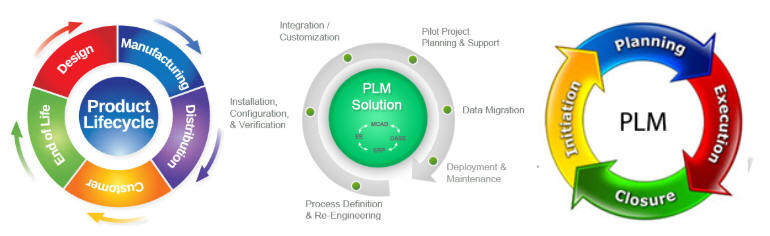
You don't have to, take a look at this list. I quit counting at 50.
Product Lifecycle Management Software
What the hell are they trying to manage?
Here is an incredible attempt by Solidworks to take control of your company.
3DEXPERIENCE Volcano is About to Erupt, Claims Bassi
Hmm Who maintains the PLM? Yes, the Infotech folks. These folks became more powerful than engineering in the 1980's. Their self serving decisions stunted Boeings entrance into PC based 3D CAD for over 15 years.
CADKEY or Catia? Boeing’s Billion-Dollar 3D CAD Mistake!
I have said this many times:
"I believe that engineering and manufacturing was much more cost effective prior to 3D CAD when the part and assembly authority was the standard manual drawing."
This is how PLM was done in the past. The drawing set was all that was necessary to manage the product. It was the product and still is. If you want to build a 1957 Chevy you just pull out the drawing set and follow the top assembly, to the sub-assemblies to the single parts. It is all there!
This is a subject that seems to have quite a bit of confusion in the PLM world.
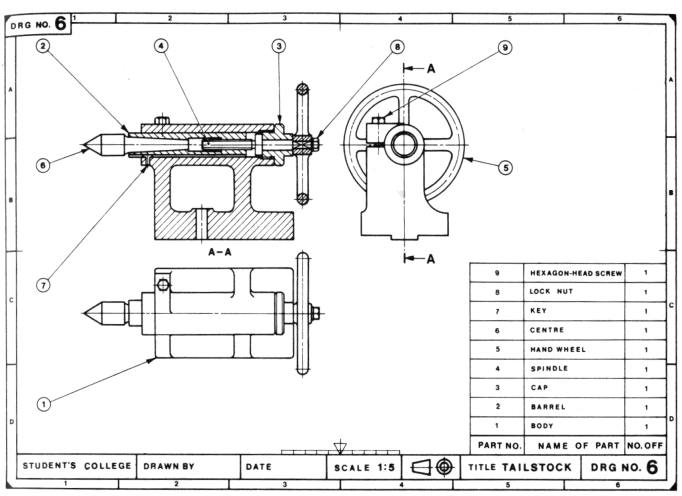
Here is a simple assembly drawing.
This was how they were done in the past. No wonderful isometric exploded view. They were just too much work and added little to define the parts. If you do not understand this drawing you should not be in engineering.
Here is a drawing from AutoCAD. You can see the draftsman put in an ISO view. Even in Autocad this was not easy and really not necessary. This is what is called an inseparable assembly. Why? Because it is welded. Many sheet metal assemblies parts are inseparable assemblies with fixed fasteners.
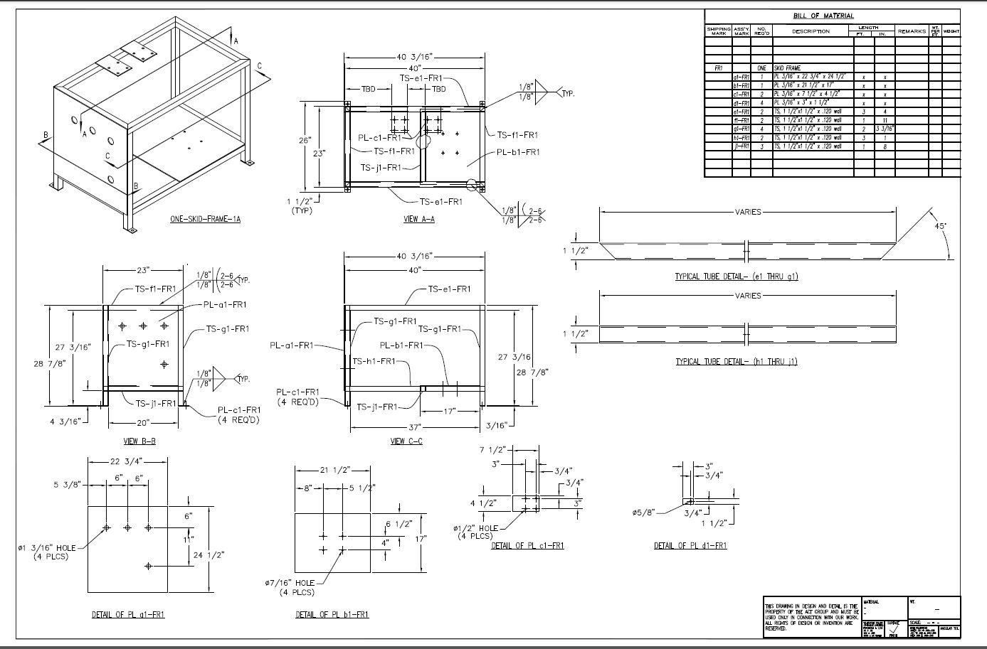
Here is the above drawing created as an AID in just a few minutes. I sold a seat of IronCAD on this presentation.
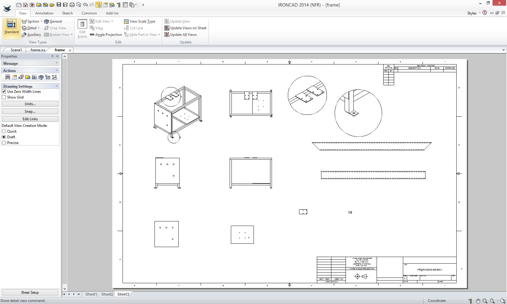
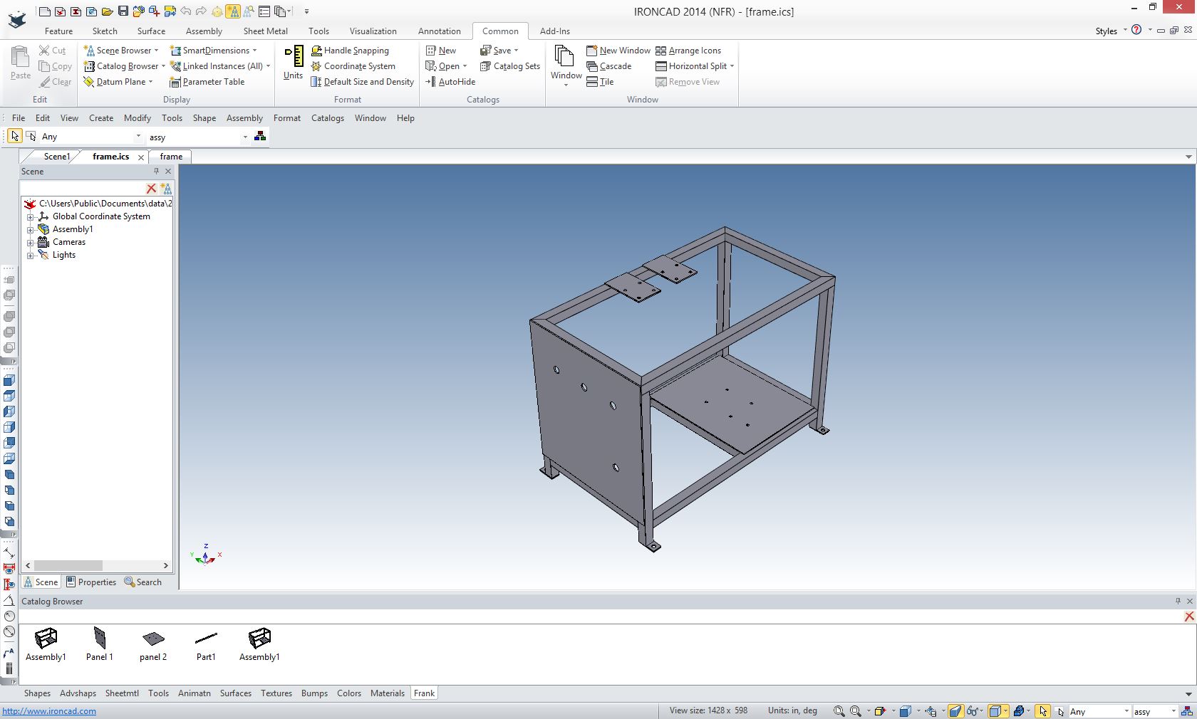
Here is the 3D model it was made from. I created the model in less than an hour. AIDs are very simple to create.
Now let's take a look at the anatomy of an Assembly Document.
This is an AID generated from the 3D model.
You can see it is made up of an exploded illustration of the assembly and a parts list. It has a drawing number.
Now we used drawing numbers in the past. We added the 3D model and started to call it the part. This has caused a confusion. The part is actually the finished product we are really talking about the model. Since we have drawings, AIDs and PMIs, we should be using EDN (Engineering Document Number) or some othere moniker that indicates there is a 3D model involved such as the AID and model or PMI. As you can see I reference a STEP file. I work for a company and they do not have my CAD system that was IronCAD. So I deliver the 3D models as STEP files and the AIDs, of course, as PDFs.
On the right is a Parts List. There are the items numbers in a bubble. This is used so we can change the part number as the part maybe revised because of an error or a design modification.
Today we call this the BOM (Bill of Materials). BOM is a complete misnomer. I explain why here.
Parts List or BOM?
We really don't need to deliver the 3D assembly. Manufacturing should have all the parts in front of them. Now manufacturing may need a sub-assembly to develop tooling to aid in the assembly process. But in the above case it just needs an illustration of how it goes together.
Here is the 3D model.
When I saw the word BOM I just chuckled and figured it came from the influence of the popularity of Autocad (an architectural drafting program) into the industrial/mechanical engineering industry.
I thought it was just renaming the parts list. But as I read about PLM they use it for something different.
What the Hell is a BOM?
Here is a excerpt from this article by Jos Voskuil, a poster child for PLM.
Document Management or Digital Thread
Next Step PLM – coordinated document management / item-centric
When the awareness exists that data needs to flow through an organization is a consistent manner, the next step of PLM implementations come into the picture. Here I would state we are really talking about PLM as the target is to share product data outside the engineering department.

The first logical extension for PLM is moving information from an EBOM view (engineering) towards a Manufacturing Bill of Materials (MBOM) view. The MBOM is aiming to represent the manufacturing definition of the product and becomes a placeholder to link with the ERP system and suppliers directly. Having an integrated EBOM / MBOM process with your ERP system is already a big step forward as it creates an efficient way of working to connect engineering and manufacturing.
As all the information is now related to the EBOM and MBOM, this approach is often called the item-centric approach. The Item (or Part) is the information carrier linked to its specification documents.
Now he references EBOM (Engineering BOM) and MBOM (Manufacturing BOM)
I truly don't have now clue what he is talking about. I cannot relate this to the past system based on the single drawing. Again it is truly shocking that the PLM Guru has never studied the past simple "standard" document control system.
You cannot have a BOM without an assembly. What do they consist of? What are these just a list of materials? Of course not, engineering assemblies are not made up of materials, but parts and subassemblies.
Manufacturing does not need a list of materials or even parts. All the information they ever needed were delivered on part or assembly drawings accessible in a archives document controls system. One of the misconceptions of PLM is that they assume that the part and sub-assembly documentation is "live" data. Nothing could be further from the truth. The archiving of the documentation is the end of the design cycle.
As I have explained above Engineering and Manufacturing are two completely separate processes. The only common thread is the archived documentation.
Look at this statement.
"As all the information is now related to the EBOM and MBOM, this approach is often called the item-centric approach. The Item (or Part) is the information carrier linked to its specification documents."
What the hell does this even mean. It is gibberish! I can see all the PLM gurus rubbing their chins and nodding their heads in approval. He seems to think there is some difference between documentation and the Item (or Part). It is only the documentation! It only comes in 3 forms today, the drawing, AID/Model and PMI. You can see that Jos really doesn't understand the basic principles of engineering documentation.
Now let's move to manufacturing.
I pick on the PLM gurus and their qualifications, what makes me qualified.
I was a board design draftsman for 17 years moved to Computervision in 1982, then was introduced to PC Based 3D CADKEY while on contact with Boeing in 1986. Saw that PC Based 3D CAD would be huge and started TECH-NET, Inc in 1987. I proceeded to sell Boeing and virtually every one of their suppliers CADKEY. I was instrumental in making the Boeing mainframe Catia 2/3/4 parts and assemblies easily available to the suppliers.
My First 17 Years or "How did we do it without 3D CAD!"
All manufacturing needed was a drawing in the past. We added the 3D model and all of the machine and sheet metal shops moved to CNC. So we created the AID and deliver both the AID and the 3D model. Until the late 1990's the AID was delivered as a paper print. It was at this time the MBE (Model Based Enterprise) came into being. It was just before Adobe Acrobat was widely accepted. I am sure the PMI would never have even been thought of if the PLM Gurus were introduced to the AID delivered as a PDF.
Today, Boeing is delivering the PMI. It was funny they never prepared any of their suppliers. Just started sending them the file. My Boeing suppliers called very confused. There was no way to view the PMI without a seat of Catia 5 or Enovia. Soon all of the large suppliers bought a seat. Of course, this fiasco is cost them a fortune and I am sure driving the cost of the parts up, without any benefit. No one accused Dassault of being stupid. But was Boeing just a useful idiot?
Manufacturing develops its own documentation. This is beyond the knowledge of the PLM gurus, since they have virtually no understanding of engineering documentation in any format, being just data to them. How in the world would they understanding Manufacturing planning?
Manufacturing delivers the parts. The cycle is complete at least for this step.
Part delivery is the first step.
Now the parts get delivered and the assembly begins. Many act like engineering has a huge role in this process. Hardly, assembly is in the competent hands of manufacturing. Manufacturing is not engineering, they have their own processes and product engineers mostly will get in the way. After the first article is made and errors are noted and fixed the engineer is off to design the next project.
What happens to the engineering documentation?
The engineering documentation, no matter what format, is archived hopefully never to be seen again. But it always has to be easily available for legal issues or new design. The document control system I envision has no dependence on a CAD system. The reason is so blatantly obvious except to the PLM Guru. This system wouldn't have enough acronyms to keep them interested.
Now remember we have two sets of documentation. The native CAD file and the engineering deliverable outside the native CAD system.
We do not care about the native CAD data. That is the problem of the system manager. Once we get the model and AID (PDF) out of system these parts can be uses as the authority. Stored as a native file, AID, PDF and maybe the model in a neutral format such as STEP. But how do we archive it?
Note: 8-12-19
I have rethought this and realize we can have the native file outside the system and available with the cloud based document control system. If there was a change in the works the part would be flagged. How is it today with files being emailed? A complete fiasco!
If we had much more flexible functional 3D CAD systems with direct edit functionality the external engineering deliverable could be used as a universal format. The parts could actually be modified by any system. But today, these parts are intrinsically tied to the native CAD system only by the AID.
There are many options once we move documentation out of the native CAD system. We could easily change CAD systems. This concept scares the hell out of the major CAD vendors. This is why you never, ever, hear any negative information out of the industry rags. There are deep pockets. These companies are worth a billion dollars and offer no more than any of the myriad of second tier 3D CAD programs. I know I sell, use and support them.
Again, I cannot make this more clear, rarely do we modify or use the existing parts for new design. And if we do we can set up systems much simpler and standard than we have today.
What must the PLM Guru understand?
Engineering Documentation has to be Standardized.
To standardize, you have to have an intimate working knowledge of the engineering process, past and present. Which I am afraid can never happen with today's PLM Gurus.
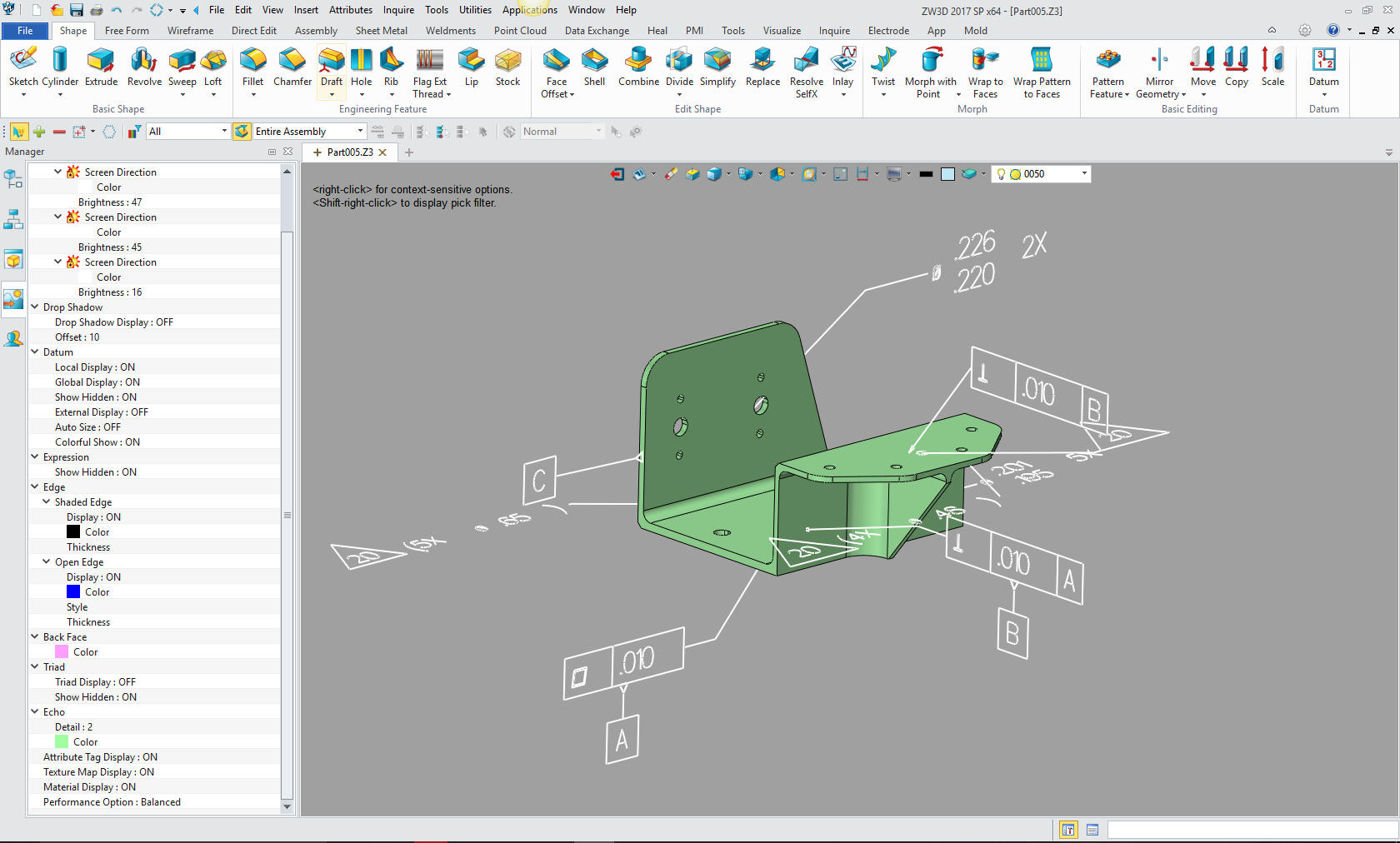
We sell and support IronCAD
and ZW3D Products and
provide
engineering services throughout the USA and Canada!
Why TECH-NET Sells IronCAD and ZW3D
If you are interested in adding professional hybrid modeling capabilities or looking for a new solution to increase your productivity, take some time to download a fully functional 30 day evaluation and play with these packages. Feel free to give me a call if you have any questions or would like an on-line presentation.
206-842-0360