|
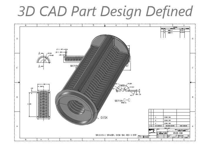
The Part – The Basic Component
of any Design
The Secret of Part Numbers
After I wrote my article on The Assembly Defined, I realized we also needed an article on part design. With the introduction of 3D design, much of the industry seems to have moved away from the basics of engineering part development and documentation. I have to give a complement out to the smaller
companies before they jump on me. They have really not changed the
process from the past. They still supply completely detailed documents
as a PDF along with the 3D model. This is very cost effective requiring
no special software or processes and lends to a much simpler document
control system. Part Design I was a board draftsman for 17 years. We did all of
the part design on a drafting board. We would create the layouts where we
developed the design in which we would "layout" the complete assembly. Of
course, designing one part at a time. We would give those layouts to
draftsman to create the detail drawings or detail them ourselves.
Part design was in the realm of the draftsman. Yes,
there were a few board engineers but very few. A couple of industries
had a group of board engineers, I remember one was Pratt and Whitney in
their Gas Turbine group. Here is a story working as a contract engineer at
Pratt. In the 1970’s. "Even though we were
taking layouts from the engineers and detailing the parts. I never
stopped being a designer. I was assigned a heat shield for the
afterburner ring. The shield was in two pieces designed radially. I
said, wow, his is going to be a horror show to create the tool. I
recommended they design it on the side. My drafting lead and supervisor
let me do a layout and they presented it to engineering. The engineering
supervisor came down and took the drawings to redesign. Like I have said
"Job Shoppers" were mostly made up of highly experienced design
draftsman. We were the very best, if you didn't know your stuff you were
out the door in a week. There were virtually no engineers on the board. Why
did Draftsmen do most of the design? Drafting was a mentoring system. You would take
your training and walk on to the job. You would be assigned a drawing.
When you were done you would give it to the checker, a senior draftsman. The checker would
put a red or yellow mark on every dimension and annotation on that
drawing. It would be given back to the draftsman to do the “pickups”.
After a few years the draftsman would be completely familiar with the
designed product. Personally, I was a born draftsman and excelled. I
was 22 and D draftsman at Boeing, they put me on layout and development of
parts, assemblies, studies and trouble shooting. The young engineers
were taking my layouts and creating drawings under my supervision. I
went to the supervisor and asked for more money. They moved my salary
from $2.90 to $3.00, I just chuckled. There were job shoppers all over. Contract
engineers making twice the money as the directs. I quit and headed to
the San Francisco Bay and got my first contract for the whopping $4.50
per hour. I never went direct again!! My last contract was with Ford
Aerospace at $35 per hour in 1988. Then I founded TECH-NET.
One more point There is a term that has grown in popularity. DFM (Design for Manufacturability). If you walked into a drafting room 40 years ago and asked the engineers and draftsman if they were designing for manufacturability? They would just give you a blank look and say "What else would you design for?" Okay, okay back to the original subject. Enter 3D CAD I was introduced to Computervision CADDS 4 3D
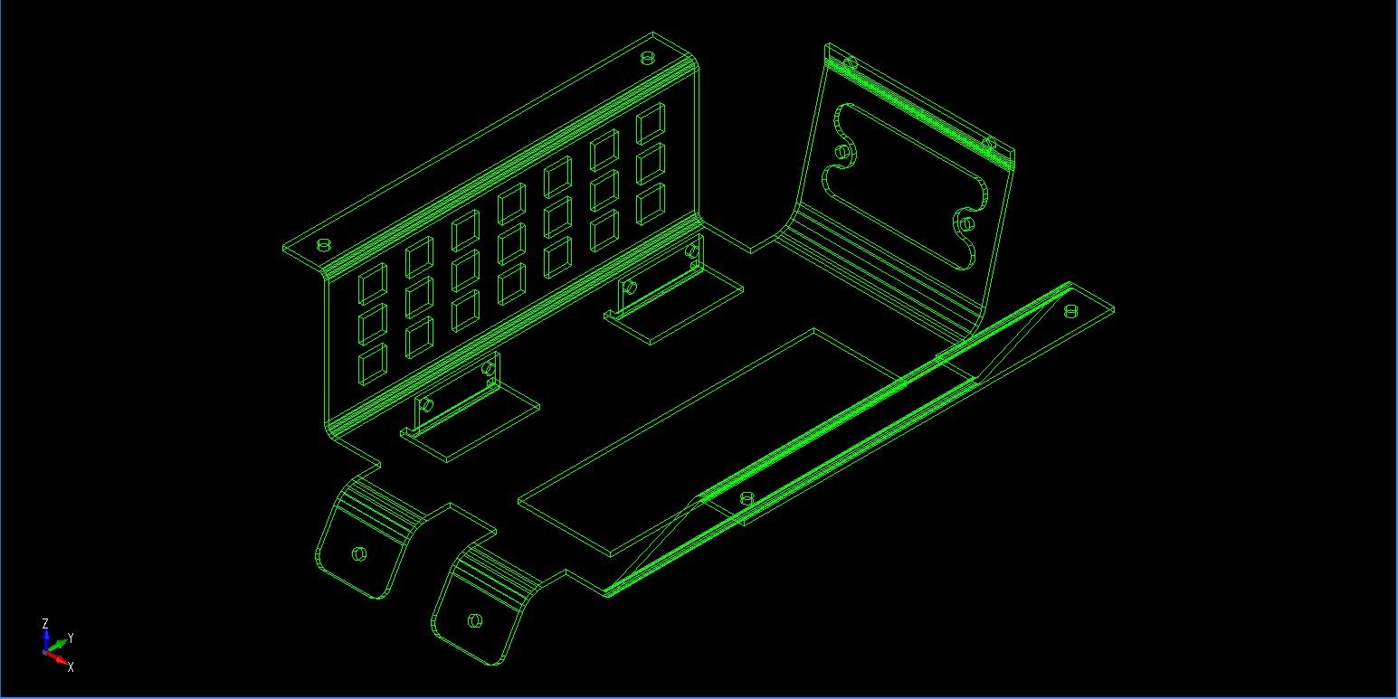
CAD system in 1982 at Williams Research in Walled Lake, MI. I was on my second stint at Williams and they had
Computervision. They allowed me to train in the evenings. I soon was
designing in 3D wireframe, with green entities on a black background.
Now I will not get into the difficulties here, but trust me it wasn’t
easy.
But getting back to part design, draftsman were the
only ones using 3D CAD. The drawing was still the final product. Even though
the print was plotted on large plotter they were still called drawings. I
personally have never created a professional scratch drawing on CAD. The
larger companies and I completely missed the Autocad bullet of the
electronic drawing and went directly to 3D CAD. The drawing was dead.
From that moment on we just detailed created views from the 3D model in
documentation modules.
Engineers were not on 3D
CAD in the beginning. But the writing on the wall began to appear in
1985 at Solar Turbines in San Diego. They let go their complete 3D CAD
direct
drafting staff and moved the
engineers to Computervision CADDS 4X. I stayed on to train them. Many protested
but were told get on the CAD system or get fired. Actually, they became
very good CAD designers and, of course, were now responsible for all of
the documentation. I am sure that cost the company a pretty penny.
But that was not the case for most companies the
draftsman was still the CAD designer. I took another contract with
Williams and then got a job in Akron at Goodyear. I was there for a week
and a Boeing job came through in Everett, WA. My family was already in
the Seattle area and I was looking forward to getting back home. I was put on the board after 4 years of 3D CAD. I was whining about not being on CAD and someone said there is a 3D CAD system on a couple of Compaqs in a small office. It was PC based 3D CADKEY. Being experienced on 3D CAD I learned the system in 2 weeks of lunch hours. It was also a wireframe modeler and very similar in operation to Computervision. I proved to the management that this system could equal the Catia 3 seats that were in the group. I have documented this in other articles but by the time I left there were 25 seats of CADKEY and soon 45 in the Flight Deck group alone. They had 1500 CADKEY seats in Boeing Commercial. I know, I know, more fricking history, but it all
has to do with part design, be patient. I again saw the writing on the wall, CADKEY cost
less than $10,000 with a 386 computer and a 19” monitor. Computevision
was $250,000 per seat and I am sure Catia 3 was over $100,000 and tied
to mainframe computers. CADKEY
could actually outperform both of those systems. All they had over
CADKEY was rudimentary surfacing that soon showed up on CADKEY in the
form of an add-on called Fastsurf in the late 1980’s. I founded TECH-NET in 1987 and started selling, supporting and training CADKEY and provide engineering services.
Virtually all of my students were draftsman with a couple of chief cook and bottle washer engineers from smaller companies. They took to CADKEY like a duck to water. I was selling CADKEY to Boeing and all of its suppliers. CADKEY was the only PC based 3D CAD program that could talk to Catia 2, 3 and 4 and was the only viable solution until the release of Catia 5. But even then CADKEY included the ability to import and export native Catia 4 and 5 native files. Actually the transition from Catia 4 to 5 was a fiasco. Catia 5 could not directly read or even utilize Catia 4 parts. CADKEY was used to convert native parts from Catia 5 and other native formats to Catia 4. The parts had to be manipulated because Catia 4 could only read a 34 meg file. Boeing would be miles ahead today if they would have standardized on CADKEY. Many suppliers are still using CADKEY, IronCAD and ZW3D to work with Boeing Catia 4 and 5 files.
I have worked with Boeing and Catia for over 30
years. Dassault is responsible for keeping Boeing one of the most
ignorant and isolated manufacturing companies. Their lack of
interoperability is beyond belief. Part Documentation
Manufacturing only gets parts. Rarely do they
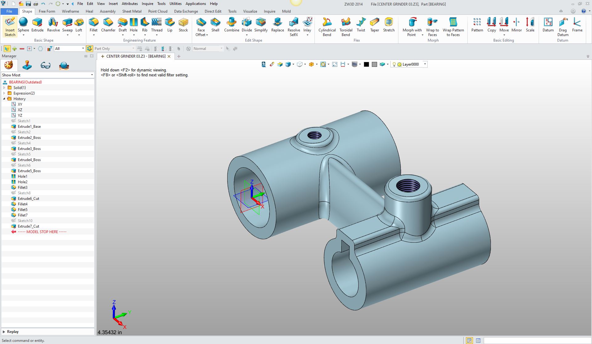
get the assembly. So they need incredibly clear definition of the parts. Designing the part is just one component of a
complete process. We design the parts and make sure of their form, fit
and function in the assembly. But we now have to completely define the
part to assure duplication at manufacturing. With the drawing it was all together the part was
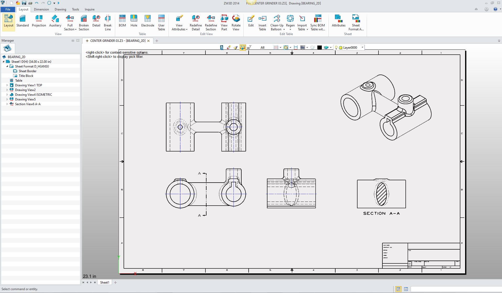
the drawing. Today we design in 3D and the documentation is done at the
end of the process. It is very, very
simple to detail a part and add other annotation and notes in the
documentation module. The
documentation is as important as the part design itself!!
Making the Model the Design Authority Today the PLM and MBE folks have tried to minimize
our documentation. It has totally failed.
As a draftsman, I really have a problem with the PLM folks. They
just do not have an understanding of what we do as designers. I really
don’t think they have even looked at the past drawing based process.
The PMI (Product Manufacturing Information) format is bringing productivity to a standstill. We send out the part information in a native system sensitive format. This makes the native part file the authority. Sadly, Catia 5 produces the more corrupt part files. Instead of making the companies produce a standard usable file the industry allows the major CAD companies to dictate the format. Yes, this is a recipe for disaster. Solidworks: MBD Model Based Definition PMI vs AID (Associated Information Document) Part design today with the large manufacturing
companies that are utilizing PLM and MBE are in chaos. Smaller
companies, luckily cannot afford the PLM and MBE overhead. Yes, their
data management requirements are much simpler and more standardized. Sadly, PLM has overly
complicated a very simple “Document Control” system, of the past.
Standard Cloud Based Engineering Document Control Standard Cloud Based Engineering Document Control Part II This is a hard subject to bring to a conclusion since it is the basis of all engineering. Everything we do begins with part design. You see the ads from the major CAD companies touting these incredible designs from airplanes to cars. If you are impressed, you really have no clue. They are all composed of mostly simple parts designed one by one by, hopefully, by those that are familiar with form, fit and function design with common industry standards and the standards of the company they are working. We used to say that an airplane was nothing but thousands of parts flying in close proximity. Product knowledge, proven standards and
So there you go Part Design in a nutshell
TECH-NET Engineering Services!
If you are interested in adding professional hybrid modeling capabilities or looking for a new solution to increase your productivity, take some time to download a fully functional 30 day evaluation and play with these packages. Feel free to give me a call if you have any questions or would like an on-line presentation.
Joe Brouwer |
TECH-NET ASSOCIATES | RENDERING OF THE MONTH | CAD•CAM SERVICES
HARDWARE | TECH TIPS | EMPLOYMENT | CONTACT